You will need to load your compiled program onto the microcontroller somehow, and typically this requires a hardware programmer.
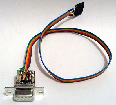
You can buy ready-made programmers, but why spend money when you can build it yourself from parts that you have lying around? The simple SI-Prog doesn't require that many parts and is supported by several popular pieces of software.
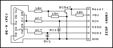
The full SI-Prog is designed to work with a variety of different chip types, as well as provide power to the microcontroller that it's programming. If one assumes that we're only going to be programming AVRs and powering the circuit ourselves then it can be simplified quite considerably! I'm using the circuit from the AVR Programmer page on Electronics-DIY.com. The circuit diagram is replicated below.
The DE-9 connector plugs into your PC's serial port, and so should be a standard female connector. For the in circuit serial programmer (ICSP) side, I recommend using a six-way single row pin socket - you can then put a matching pin header on your circuit board (or plugged into your breadboard) to allow you to quickly and easily connect and disconnect the programmer. The nearest-sized sockets and headers I found were eight-way, but you should be able to cut them to size with a sharp pair of wire cutters.
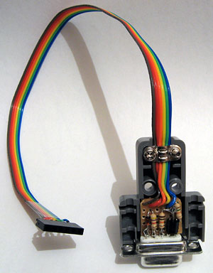
With a bit of work (and both sides of the circuit board) you should be able to cram the programmer into a D-sub connector hood.
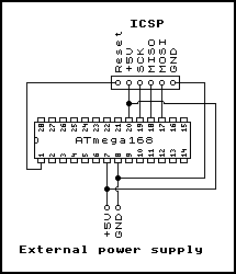
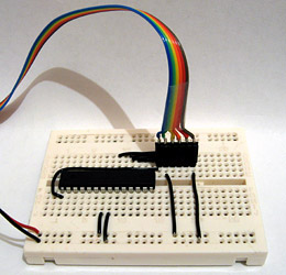
Now that you have a programmer, you need some way to test it. A suitable circuit for the ATmega168 is illustrated below: the programming header is connected to the AVR's RESET (1), MOSI (17), MISO (18) and SCK (19) lines, as well as its power supply — both VCC (7) and AVCC (20) are connected, as well as GND (7). Consult the ATmega168 data sheet for more pin definitions.
The pins in pin headers usually have one long end and one short end either side of the insulating block. You may find that they spring out of breadboards if you put the short end in first, or fail to make a proper connection to the programming header if you put the long end in first. To even them out, you can slot the short ends into the breadboard and very carefully push the tops of the pins against a flat, hard surface — they can be pushed through the insulating block, but make sure that you don't bend them!
Once you have built the circuit, download and install PonyProg. This is a free, easy-to-use GUI program that can be used to program the AVR. The first time you run the application, it will prompt you to configure it — click OK on the two dialog boxes.
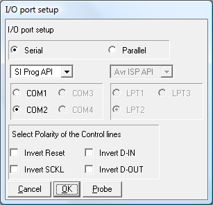
To test your programmer is working, click Command, Read all. This will run for a minute or so.
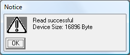
When it has finished reading you should receive an affirmative message, followed by a display of the AVR's program memory. A blank AVR will read back 0xFF for every byte of program memory — it would be nice to use the programmer to put something useful in there instead.
A simple "Hello World" program for a microcontroller could be to flash an LED connected to one of its output pins on and off. This section will take you through writing such a program.
AVR programs can be written in C using free tools. One of the easiest ways to get started is to use the AVR Studio IDE (registration required) along with the WinAVR suite. Download and install both tools — I installed AVR Studio before WinAVR, and didn't need to perform any additional configuration afterwards.
When you start AVR Studio, it will prompt (by default) whether you'd like to create a new project or open an existing one. If you had previously switched this dialog off, you can access it via the Project, Project Wizard menu. Start by creating a new project.
When you click Next you will be prompted to select a debug platform and device. In the absence of a hardware debugger, select AVR Simulator 2 with ATmega168 as the device. This will allow you to simulate your program within the AVR Studio IDE. Finally, click Finish and your new project will be displayed with a blank source file.
We now have a blank source file — but how does one control the input and output pins, to flash the LED?
The ATmega168 arranges its I/O pins into ports. Each port has up to eight digital I/O pins. Some of these pins have special functions (for example, the pins we're using to program the AVR — MOSI, MISO and SCK — are all in port "B") but can generally be used as input or output pins with optional interal pull-up resistors. Each port has three associated registers.
On reset, the DDxn and PORTxn registers are set to 0. This means that initially all pins are inputs with the pull-up resistor disabled — they float, in other words.
As an example, suppose you wanted to drive pin 28 on the ATmega168 high. This would require configuring it as an output (DDxn) and setting its output level to a 1 (PORTxn). According to the ATmega168 datasheet, pin 28 is PC5 — it is represented by the fifth bit in the port "C" registers. To set it to be an output you would therefore need to set bit 5 in DDRC and to drive it high you would also need to set bit five in PORTC.
For more detailed information, consult the ATmega168 datasheet.
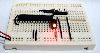
Rather than using pin 28, I've chosen to use the more accessible pin 14, which turns out to be PB0. Connect an LED between the pin and ground via a 470Ω current-limiting resistor. Using the above information about the I/O port registers, the code is a rather simple bit of C:
#include <avr/io.h>     /* IO port definitions. */
#include <util/delay.h> /* Utility functions for delay loops. */

int main(void) {
    /* Set the 0th bit of port B to be an output. */
    DDRB |= (1 << 0);
    /* Infinite loop. */
    for (;;) {
        /* Toggle the state of the 0th bit of PORTB via the PINB register. */
        PINB |= (1 << 0);
        /* Wait 500ms. */
        _delay_ms(500.0);
    }
}
avr/io.h provides the definitions for the I/O port registers (DDRB and PINB in this example) and util/delay.h provides the _delay_ms function.
Build the project using Build, Build (F7). If you look in the resulting directory named default in your project's directory you will find a .hex file — this is the program file you can send to the microcontroller. Open it using PonyProg's File, Open Program (FLASH) File menu then click Command, Write All to program the microcontroller. Confirm the overwrite prompt, then wait for the program to be sent and then verified. When PonyProg has finished the microcontroller will reset and the LED should start flashing!
You may have noticed that one warning is reported when building the project. This is because the CPU speed has not been explicitly defined, so compiler can't be sure it's got the length of the delay loop in the _delay_ms function correct (the delay is created by executing a known number of clock cycles). You can remove the warning by explicitly setting the clock speed which — by default — is 1MHz. To set this, click Project, Configuration Options and typing 1000000 into the box marked Frequency.
PonyProg does program quite slowly, and it can be a hassle to navigate a GUI to reflash the microcontroller each time. The command-line AVR programming utility avrdude will have been installed with the other tools and can speed up the development process somewhat! Create a file named flash.cmd in your project's directory, containing the following commands (make sure you change the COM port number and filename as approprite):
@echo off
avrdude -p m168 -c siprog -P COM1 -U flash:w:default/Blinkenlight.hex
if errorlevel 1 pause
Double-clicking the file will now quickly send the program to your AVR.
If you open PonyProg and click Command, Security and Configuration Bits the following dialog will appear (or something similar):
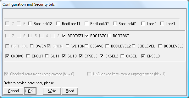
These are the AVR's fuse settings, and these control some of the low-level functionality of the chip. For example, the various CK fuses select the type of CPU clock to use — if you wish to use an external resonator rather than the internal 8MHz RC oscillator then you would need to change these fuses according to the type of resonator and its speed. Consult the ATmega168 datasheet before playing with these fuses, as you can lock yourself out of the chip, unable to reprogram it! Be aware that a fuse set to a 1 in the datasheet should be unticked and a fuse set to a 0 in the datasheet should be ticked in PonyProg.
If you do misconfigure the clock fuses, you may not be able to reprogram the device to correct them. If this should happen to you, build an external crystal oscillator (such as one of these designs) and connect its output to the XTAL1 pin (9) on the ATmega168. Using a 1MHz oscillator I have been able to get the AVR running again so I could correct its fuses.
One fuse to try with the flashing LED program is the CKDIV8 fuse. This divides the clock frequency by eight which, when coupled with the default 8MHz internal RC oscillator, results in the 1MHz clock speed we specified above. If you untick the CKDIV8 box and click Write in PonyProg the LED will start flashing eight times as fast. To compensate for this in software, set the project configuration's frequency field to 8000000, rebuild the project then reflash the microcontroller.