TI Keyboard
Tuesday, 15th November 2005
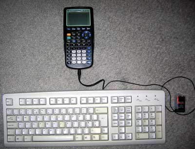
Once again, I waste my time doing something remarkably useless - it's trying to connect a keyboard to my TI graphing calculator!
Idea
Alas, this is not an original idea - I had seen some work done on this in the past, and tried fiddling with the code myself, not really understanding much of it. I decided to have a go - from scratch, and on my own.
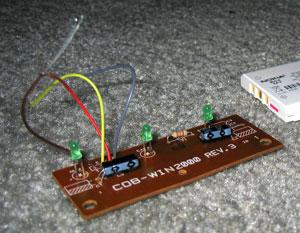
Constructing the hardware
I decided to butcher an old, suitably discoloured keyboard (in a nice way, though, so if all went wrong I could reassemble it). I don't have a soldering iron, nor any sort of decent cabling or plugs so I planned to just cut and strip the wires inside the keyboard and attach (by twisting together and large amounts of Sellotape) a power cable and 2.5mm stereo minijack plug (the TI has a 2.5mm stereo minijack socket on it as a data port).
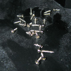
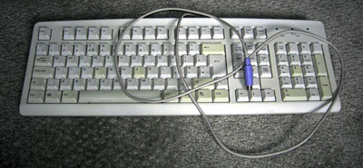
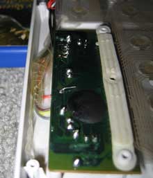
I'm not sure they put enough screws into this thing... (by contrast, my main keyboard has a whopping 2 screws in it - this keyboard's designer was clearly paid by the screw!)
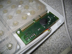
Finally (and with a slightly sore wrist), I get to the bit I need - the keyboard controller board. The circuit board has the four leads soldered straight into it - I'd been hoping for the more typical sight of a block that the cable plugs into, but unfortunately it looks like I'll be cutting wires and hoping not to snap them off by accident. The four wires have been labelled VCDO - I'll cross my fingers and assume these stand for VCC (+5V), Clock, Data and 0V.
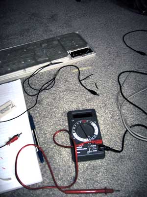
Out it comes, the wires are stripped and reattached. I then tested all the leads using my multimeter and created some stunning ASCII art to remind me what went where:
HARDWARE SCHEMATIC:

PS/2 SOCKET:                               TI CONNECTOR:

  6.-++-.5      4: VCC   >-[+5V]                _
  /o || o\      5: Clock >---< 1: Red    Tip   /_\.
 |   ++   |     1: Data  >---< 2: White  Ring  }_{
4|o      o|3    3: Gnd   >-+-< 3: Copper Base  | |
  \      /               __|__                 |_|
   \o__o/                 ---  0V             /   \.
   2    1                  '                  \___/===> To TI
 ^ Note that this is the SOCKET view
and not the plug view for a PS/2 port.
With that done, I taped down the connections and screwed the whole thing back together. Tapping a 9V PP3 battery to the power leads makes the keyboard boot up; doesn't look like it's broken quite yet!
Writing the code
What with the hardware now hopefully complete, it's a simple case of writing the code to support the keyboard. *cough cough*
Basically, I need to write an implementation of the AT protocol. The protocol is fairly simple, but unfortunately the keyboard generates the clock signal for us (the TI doesn't have accurate timing at all - it's an RC circuit, and so the clock rate drops as the batteries go flat). Let's hope the TI can keep up!
I guess the easiest code to write would be code that sets the output high (as it's an open collector circuit, high is the default level - either side can pull this low and hold it there) then poll the clock and wait for it to drop then go back up again. The clock line maps to bit 0 of the link port, and the data line to bit 1 of the link port. The TI's data IO port can be controlled using these two lower two bits of the hardware port equated as 'bport' (port 0) in ti83plus.inc
Here's what I tried;
init_all:
    ; Set link port high
    ld a,%00000011
    out (bport),a


wait_bit_low:
    in a,(bport)        ; Read in the status of the bport.
    and %00000001       ; Mask out bit 0 (clock)
    jr nz,wait_bit_low  ; Is it non-zero (high?) If so, loop back.

wait_bit_high:
    in a,(bport)        ; Read in the status of the bport.
    and %00000001       ; Mask out bit 0 (clock)
    jr z,wait_bit_high  ; Is it zero (loop?) If so, loop back.

    ret                 ; Break out of the program
Strange, whatever I do - init the keyboard, tap keys, nothing happens. The program goes into an endless loop. Using the 9V to manually set the line low then high again, I realise something - I keep forgetting that the port works backwards, and that writing %00000011 sets the status to %00000000 - and when a line is held low by either device, it can't be brought up again very easily. Replacing the offending line with xor a to clear it to zero worked a treat - pressing any key on the keyboard exits the program.
Each "packet" on the AT protocol (it's a bit grand to call it that) is made up of 11 bits - 1 start bit, 8 data bits and 2 parity/stop bits. A djnz loop to get the 8 bits and a handful of rotate instructions to populate the result byte gives me this:
.module AT_Protocol

at_timeout = 255

at_get_byte:
    ; Clear Link port
    xor a
    out (bport),a

    ; Get the start bit:

    call _wait_bit_low
    call _wait_bit_high


    ; Now we need to get the 8 bits for the byte

    ; Reset the output byte
    ld c,0

    ld b,8

_get_byte_loop:

    call _wait_bit_low

    ; Now we get the bit itself
    in a,(bport)
    rrca
    rrca
    rr c

    call _wait_bit_high

    djnz _get_byte_loop

    ; Get the parity/stop bits

    call _wait_bit_low
    call _wait_bit_high
    call _wait_bit_low
    call _wait_bit_high

    ; Clear flags, load code into accumulator and exit
    xor a
    ld a,c
    ret

_get_byte_fail:
    ; Set nz to indicate failure, return.
    or 1
    ret


_wait_bit_low:
    push bc
    ld b,at_timeout
_wait_bit_low_loop:
    in a,(bport)
    and 1
    jr z,_waited_bit_low
    djnz _wait_bit_low_loop
    pop bc
    pop bc
    jr _get_byte_fail
_waited_bit_low:
    pop bc
    ret

_wait_bit_high:
    push bc
    ld b,at_timeout
_wait_bit_high_loop:
    in a,(bport)
    and 1
    jr nz,_waited_bit_high
    djnz _wait_bit_high_loop
    pop bc
    pop bc
    jr _get_byte_fail
_waited_bit_high:
    pop bc
    ret
Not too tricky at all! Amazingly, this code ran first time too. (Amazingly for me, that is). The test program just reveices a byte from the keyboard and displays it on the screen.
One minor problem is that sometimes the code received differs by a bit to what it should (you can see this by holding down a key and noting how sometimes the code is different - I've written a short program that just displays the code on-screen when it's received). Consulting my AT protocol notes, I find that "After the clock line goes low a 5-microsecond pause is used so that the data line has time to latch." Maybe my pause isn't long enough?
Sadly, that did quite the opposite - the results are even more unpredictable. I guess it would be more better to try speeding up my code, rather than slowing it down..?
After increasing the speed a little (without unrolling all the loops, that is) the routines are (by and large) slightly more accurate. Still not perfect, but they'll do for the time being. If I press a key the release it just before it repeats, the accuracy is 100% perfect - I suspect that the problem is that in the time the rest of my program has drawn the last keycode, the keyboard has pottered away and tried to output another byte and I'm jumping in half way through. I guess I'll have to write some clever buffering code to handle that!
Interrupts
I thought that an ideal way to handle the timing/speed problem was to create a piece of code that could be loaded as a sort of driver. The calculator would be set up into interrupt mode 2 and would call the driver 100-or-so times a second. The code could then try to see if a byte was coming in, and if so it would add it to a buffer. A routine isolated from the rest of the code could then read a byte from the buffer and shift all the other items down to replace it - a sort of FIFO stack.
The Z80 has three interrupt modes; 0, 1 and 2. Interrupt mode 0 is pretty useless to us; interrupt mode 1 is the normal mode of operation. In this mode, the CPU pushes the program counter to the stack then jumps to memory location $38 every time an interrupt occurs. The interrupt handler then swaps the main CPU registers away with their shadow register pairs, does something, then swaps the CPU registers back again. Finally, you pop the old program counter off the stack and jump back to where you were. You could think of it as having a second thread running, only a lot less hi-tech and more restrictive.
Interrupt mode 2 is a stranger beast. The main difference is that it doesn't just jump to $38 - it creates a 16-bit address using the register I as the most significant byte and a byte off the data bus as the least significant byte - effectively, we have a 16-bit number made up of i*256+?. The CPU then loads the value in the memory location pointed to by this 16-bit value, then calls this address.
What does this mean for us? Well, it means that rather relying on the interrupt at $38 we can load our own interrupt into memory!
We need to do three things:
- Create a 257-byte lookup table aligned to a 256-byte boundary for the CPU to read from after it has build up the 16-bit address.
- Set the I register to the most significant byte of the start address of our lookup table.
- Copy our interrupt handler to the location our table points to, switch the interrupt mode to two and enable interrupts.
The way I've done this is:
- Filled memory locations $8700 to $8800 (inclusive) with the byte $86.
- Loaded $87 into the I register.
- Copied my interrupt handler to $8686
My interrupt handler at $8686 is a simple jp instruction to jump back to my program for the sake of practicality.
Unfortunately, this approach doesn't work (and I tried a lot of different ways to get it to!) One reason for failure is that in im 2, the main interrupt handler at $38 isn't getting executed. The TIOS relies pretty heavily on this interrupt to work; most functions cause a pretty nasty crash or do other strange things. Fine, I say to myself, and replace my reti call at the end of my interrupt handler with a jp $38 to manually call the TIOS interrupt. The behaviour gets even stranger - calling ionFastCopy (a function, non-TIOS related, to copy the display buffer to the LCD) causes strange rippling effects to appear on the LCD, followed by a full-out crash when I finally quit the program.
On top of all this, the few times I can get a display of the key buffer I can see that it's not updating very frequently... The interrupt is not checking the port frequently. All this for nothing!
As far as I can see it, the only way for an interrupt-based technique to work would be for the TI to have a hardware interrupt - using the keyboard's clock connected to the CPU, so that whenever the clock goes low the TI could spring into action and receive the byte. Seeing as the only access to the CPU I have without invalidating my warranty is via the data port, I'm a bit stuck.
Back to square one
I guess the only way is to agressively poll the port... First up, I rewrote the code so that instead of displaying a decimal version of the code, I'd display a hexadecimal version - significantly easier to read, faster to convert. I then painstakingly noted down every key's scancode from this into a useful include file.
One problem with the original TI keyboard project was that it had problems with input; it would occasionally forget about shift being pressed, or accidentally repeat keys. I think I now know why...
On an AT protocol keyboard, scancodes are sent every time a key is pressed and again when the key is released. To differentiate between the two different actions, when a key is released the scancode is preceded by the special code $F0.
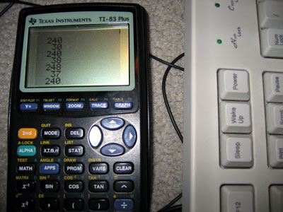
I reckon that the problem was that the function to get a byte would have been called, followed almost immediately with the code to translate/display it. What I intend to do instead is to get bytes in a loop and add them to a buffer until either the routine times out (no more bytes being sent) or the buffer is full (shouldn't happen!)
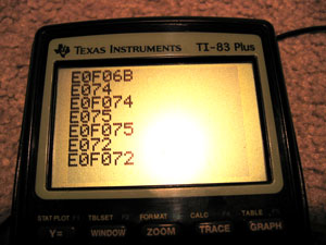
As you can see, this system works. The above codes are special ones generated by pressing some of the extended keys (the cursor keys) - they send the code $E0 followed by the key itself. Some of the codes are downright silly - PrintScreen sends the command string E0F07CE0F012 when released - Pause sends E11477E1F014F077!
Infuriatingly... this is STILL not perfect! I'm still losing some bytes. What to do - if only there was a way to control the keyboard, to stop it from scanning... wait a minute...
Controlling the Keyboard
Sending a byte is not too different from receiving a byte - you hold the clock and data lines low, then just the data low, then write out the bits as the keyboard requests them on clock. The easiest code to transmit is $FF - keyboard reset. According to my notes, the keyboard should respond with the power-on self-test byte as well as resetting. Lo and behold, the keyboard lights flash and I get $AA back - the self test has passed. I also get $E8 back, and my notes don't mention $E8 anywhere, but I'll ignore that for a minute and bask in the glory of it otherwise working perfectly.
The next code I try is $EE. This is the echo code - in theory, the keyboard should send back $EE. Sadly, it doesn't. Damn. It just resets and sends back $AA, though it sometimes sends back $B8 as well.
On close inspection, it seems pretty obvious what I've done wrong - I'm completely neglecting to send the parity and stop bits. Oops. After adding them, the keyboard responds $EE to my $EE - which is quite correct! The parity is hard coded, so I'm glad it works.
Trying another code, $F2, gets the keyboard to spit back an unfriendly $FE - which translates as "resend, you idiot". $EE is %11101110, which contains 6 set bits. $F2 is %11110010 which contains 5 set bits - the parity needs to be reversed. Hopefully calculating the parity shouldn't consume too many clock cycles - after I extract the bit to send, I need to add it to another counter. I can then use the lowest bit of this counter as my parity bit.
Thankfully, I have sufficient time to calculate the parity - the keyboard now responds FAAB83. $FA is the ACK code, AB83 are the ID bytes. Scarily, my notes say that the ID bytes are $83 then $AB - I'm going to hope that this is an error in the notes - I doubt my routines are going to be able to mix up whole bytes!
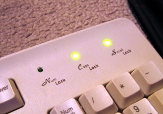
Now for the main reason you'd want to send codes to the keyboard - to flash the LEDs, of course! The code is $ED - the keyboard should respond with an ACK ($FA), to which I send the status byte (the lower 3 bits control the LEDs). The code is pretty simple (albeit without any checking on the ACK):
    ld a,$ED
    call at_send_byte   ; Command
    call at_get_byte    ; ACK
    ld a,%00000101      ; Caps Lock and Scroll Lock on
    call at_send_byte   ; Command
    call at_get_byte    ; ACK
Ace. I'll add the equates for the various commands to my include file. No doubt I can get some more done with this project tomorrow...