Z80 computer - Lines, cubes and inverted text
Sunday, 5th October 2008
I've made a few additions to the operating system for the computer. The Console module, which handles text input and output, now supports "coloured" text - that is you can set the text foreground and background colours to either black or white. This functionality is exposed via the BBC BASIC COLOUR statement. If you pass a value between 0 and 127 this sets the foreground colour (0..63 is white, 64..127 is black) and if you pass a value between 128 and 255 this sets the background colour (128..191 is white, 192..255 is black).
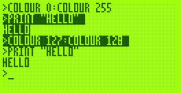
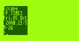
The image on the right also demonstrates another addition - you can set the text viewport to occupy a partial area of the display. This is most useful when coupled with the ability to define graphics viewports, which I have yet to add.
That said, I have started writing the Graphics module. So far all it can do is draw clipped lines, and this functionality is exposed via BBC BASIC's MOVE and DRAW statements. MOVE sets the graphics cursor position - DRAW also moves the graphics cursor, but also draws a line between the new position and the previously visited one.

I cannot use drawing code I've written for the TI-83+ version due to differences in the LCD hardware and the way that buffers are laid out. The popular way to lay out graphics buffers on the TI-83+ is as follows:
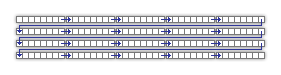
Each grey block represents 8 pixels - one byte in LCD memory represents 8 pixels grouped horizontally. The leftmost bit in each 8-pixel group is the most significant bit of each byte. The data is stored in the buffer so that each row of the LCD is represented by 12 consecutive bytes. This left-to-right, top-to-bottom arrangement should seem sensible to anyone who has worked with a linear framebuffer. However, due to the way that the LCD I'm using is arranged, I'm using the following buffer layout:
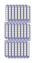
The LCD hardware groups pixels vertically, but when you write a byte to it its internal address pointer moves right. Furthermore, the most significant bit of each byte written is at the bottom of each group. This may sound a little confusing, but actually works out as more efficient. Writing text is easy; I'm using a 4×8 pixel font, so all I need to do is set the LCD's internal address counter correctly then write out four bytes, one for each column of the text (other sensible font sizes for the display, such as 6×8 or 8×8 are just as easy to display).
Another example of improved efficiency is if you deal with pixel-plotting routines. Each pixel on the display can be addressed by a buffer offset and an eight-bit mask to "select" the particular pixel in an eight-pixel group. With this arrangement, moving the pixel left or right is easy; simply increment or decrement the buffer offset by one. Moving the pixel up or down is a case of rotating the mask in the desired direction. If the rotation moves the pixel mask from one 8-pixel group to another (which only happens every eight pixels) the buffer offset needs to be moved by 128 in the correct direction to shunt it up or down.
On the TI-83+, moving the pixel up or down requires moving the buffer offset up or down by 12; moving the pixel left or right is a rotation as before with a simple buffer offset increment or decrement to move between 8-pixel groups.
In Z80 assembly incrementing or decrementing a 16-bit pointer by one is a single instruction taking 6 clock cycles; moving it by a larger offset takes at least 21 clock cycles, 42 if you include backing the temporary register such an operation would take.
What may be interesting to see is how well a raycaster would work on a system that has video memory arranged into columns.
Without wishing to be typecast as that programmer who loves spinning cubes, I also wrote a cube-spinning demo to test the line drawing routines as well as some integer arithmetic routines I've added (the Z80 can't multiply or divide, so these operations need to be implemented in software).
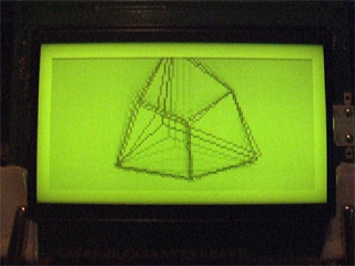
It runs fairly smoothly (bearing in mind the 2MHz clock speed). The second half of the video has the Z80 running at 10MHz; it actually seems quite stable even though the LCD is being accessed at nearly five times its maximum speed (the system did need to be reset a few times until it worked without garbling the display).