Varying wall heights in a 3D engine for the TI-83+
Monday, 25th October 2010
I've done a little more work on the 3D engine for TI-83+ calculators that I mentioned in the previous entry. The main difference is in limited support for varying the heights of floors and ceilings, illustrated in the following screenshots.
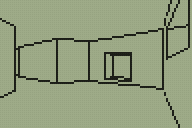
Walls now refer to one or two "sectors". A sector is a 2D region of the map of any size or shape; it can be concave or even have holes in it. Walls are also grouped into convex regions named subsectors for rendering purposes. Each wall has a sector in front of it and a sector behind it; these sectors have a specified floor and ceiling height. There are now two types of wall; a "middle" wall which connects the floor and ceiling of the sector in front of it and an "upper and lower" wall which connects the ceilings of the sectors on each side and the floors of the sectors on each side.
This makes occlusion a little trickier and determining where to draw lines around the edges of walls even more so!


The previous version of the renderer worked by drawing walls back-to-front, clearing rectangles the height of the screen behind the wall segments as they were drawn. The first attempt to improve this exchanged rectangles the full height of the screen with trapezia. The screenshot to the left shows the bounding rectangle around each wall segment being filled and the one to the right shows each wall filled as a trapezium. (As before, clicking an image with a border will display an animated screenshot).


Rather than attempt to calculate where lines should be drawn around wall edges I thought I'd experiment with dithered wall fills instead. The left screenshot shows this addition (each wall has a different shade) and the right screenshot shows the addition of support for wall heights (still drawn in the simple back-to-front technique, resulting in significant amounts of overdraw).
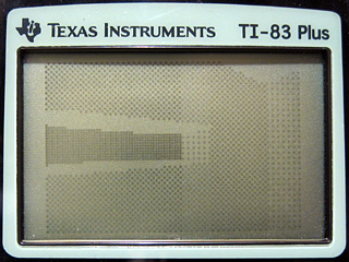
Unfortunately, the LCD on the calculator copes rather poorly with dithered fills; the above photograph was taken at the highest contrast setting. Rotating the camera to look at walls with a different dither pattern brings the world back into view. This is rather unacceptable, and is something I ran into with my previous implementation. I think I'll stick to stroked wall outlines rather than filled walls.

I had been experimenting with a new level design in the C# prototype of the engine that added another room accessible via a tunnel from the starting room. I added some code to the C# program to output the level data in a form that could be assembled into the Z80 version. This is shown above, having reverted to a simple wireframe view in anticipation of the new wall drawing code.

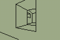
The new way to implement occlusion works very differently to the previous one. I had been sorting the geometry from back-to-front and rendering it in order, drawing walls in the foreground on top of walls in the background. This wasn't very efficient and wouldn't scale well. The new approach renders from the front to the back and works on information stored about each column of pixels on the screen. The screen is 96 pixels wide, so there are 96 columns to deal with. A counter is set to 96 at the start of rendering. When a column of a wall is rendered, a flag is set to indicate that that column has been completed and the counter is decremented. When the counter reaches zero, that means that every column on the screen has been completed and the renderer terminates. This is demonstrated in the above screenshot when compared to the previous one; walls that are some distance away from the camera (and behind other wall segments) are not always drawn as the renderer has decided that it has finished before reaching them.
An obvious issue with the above screenshot is that even though some of the geometry is culled, individual walls can still be seen through other ones.

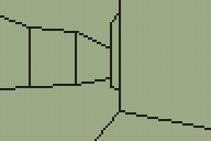
Part of the solution is to use a custom line-drawing routine that checks each pixel against the completed columns table. If a column is marked as completed, the pixel is not drawn; if it isn't, the pixel is drawn. This is shown above.
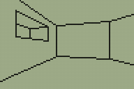
I previously mentioned that there were two types of wall; "middle" walls (solid ones from the floor to the ceiling) and "upper and lower" ones (these have a hole in the middle). Only "middle" walls flag a column as being completed, as you need to be able to see through the hole in "upper and lower" ones. This causes the rendering bugs in the previous screenshot above and below the holes in the wall. The way to fix this is to add two new per-column clipping tables; one which defines the top edge of the screen and another which defines the bottom edge. These both start at the maximum values (0 for the top edge and 63 for the bottom) and are reduced whenever an "upper and lower" wall type is encountered.

The new code to do this is demonstrated in the above screenshot. There is still, however, a bug in this implementation. The per-column clipping tables are updated by the code that draws the line along the bottom or top edge of the hole in the wall. If this line is partially (or completely) off the screen, these tables are not updated and the rendering bugs appear again (as demonstrated at the end of the above screenshot). A final manual pass over parts of the line that are clipped off the screen corrects the issue:

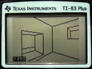
As can be seen in the bottom left corner of the above screenshot I have added an FPS counter. This is accompanied by code that scales movement by elapsed time so you move at the same speed regardless of how long each frame takes to render. The engine is quite slow (and could no doubt be heavily optimised by someone who's good at assembly) and has quite a few bugs in it but it's certainly looking a little better than it did a week ago. As I only have a regular TI-83+ I'm aiming for something usable at 6MHz; the more modern calculators can run at 15MHz but this feature is not used in the demo.
For those interested in trying the demo on their calculators, click on the above image to download an archive containing a TI-83+ and TI-83 binary. As before, this is experimental and may well crash your calculator, so please back up any important files first!