TV Demonstrator for TI calculators
Monday, 11th October 2010
I've been tinkering with a number of small projects recently. I've resumed work on an LED clock for my bedroom (using a 32×8 LED display) and written an experimental BASIC interpreter in C# which I may try to turn into an assembler (implementing assembly statements as BASIC ones). In the mean time, I have finished one project — a device to display a calculator's screen on a television set.
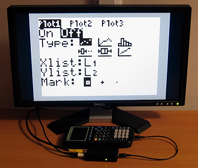
Texas Instruments also manufacture a product that allows you to view the screen contents of a calculator with supported hardware on a TV; here is a video demonstrating it. The additional hardware (either on special "ViewScreen" calculator models or built into the more advanced calculators such as the TI-84+) allows the device to mirror what is sent to the calculator's LCD in real-time.
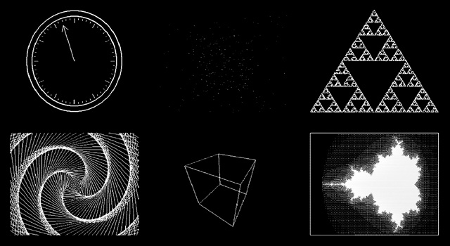
I do not have one of these calculators, just a plain old TI-83+. However, this calculator (as well as the older TI-83 and TI-82) allows you to capture a screenshot over the link port. Pressing a button on my device captures a screenshot in this manner and displays it on the TV. This relies on the calculator being in a state where it can respond to these screenshot requests, so is not ideal, but considering that the TI Presenter costs $300 and relies on special hardware inside the calculator and mine should cost less than a tenth of that in parts and work with older calculators I think it's a decent compromise.
I had previously believed that NTSC composite video signals used a negative voltage for sync pulses. I have since found documents that indicate that the sync, black and white levels are the same as those for PAL. The timing is, naturally, different but as there's no need to change the hardware it makes supporting both NTSC and PAL relatively straightforwards. This contraption can be set to operate in either NTSC or PAL mode by sending the real variable M to it from the calculator, with a value of 60 for NTSC and 50 for PAL.
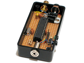
I acknowledge that this is not the most useful of projects (unless you're a maths teacher with an interest in electronics) but the code may be of interest for other projects. A handful of inexpensive parts can get you a picture on a TV from a 96×64 monochromatic frame buffer (the 1KB RAM on the ATmega168 doesn't allow for much more, alas).
More information and downloads can be found on the TV Demonstrator project page.
Text and filled shapes for the dsPIC33 VDC
Thursday, 22nd July 2010
The dsPIC33 video display controller project I am working on needs to support several common text output and drawing operations offered by existing BBC BASIC implementations. The previous demo included basic point, line and circle outlining functions, but I also need to output text and outline (or fill) rectangles, circles, ellipses and triangles. On top of that the drawing operations need to support multiple colours and plotting modes. Owing to processing power and memory limitations the output is black and white only but different "shades" can be implemented with dither patterns. The plotting modes allow you to perform logical operations between what you are drawing and what's currently on the buffer — for example, you could fill a circle that is logically ORed with the existing background or draw a line that inverts every pixel along its length rather than applying the new colour.
Filled rectangles and text output produce the above image.
Finding suitable algorithms for some of these routines has been a little tricky at times. Due to the way that filled shapes can be set to invert (rather than overwrite) what's on the background there has to be zero overdraw and the outline of filled triangles should exactly match the outline of a triangle drawn by plotting a line between its three vertices; this makes combining triangles to form more complex shapes possible, as you can guarantee that the overlap between the two shared vertices of a pair of triangles covers the same pixels as a line drawn between those two vertices.

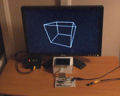
Filled triangles produce a solid cube.
I ended up writing a program in C# that would plot a random triangle using the triangle filler I was attempting to write and then compare its outline to that of a triangle drawn by plotting lines between the three vertices. The final code is chock full of special cases and workarounds but has been tested against hundreds of thousands of random triangles and seems to be working!
Due to a shortage of memory there is only a single frame buffer, which (naturally) means there is no double-buffering and hence smooth animation becomes a little tricky. When connected to a TV one can take advantage of the vertical blanking period to update the buffer (this is a period below and above the active display where you only need to feed sync signals, not image data, to the TV) and still get decent effects as long as you don't try to do too much. The LCD has no such vertical blanking period and so some of the demos look rather flickery.
I have captured a video of the output of the circuit when running the demo which can be seen above. The horizontal grey lines are a limitation of my video capture card; these lines appear correctly as alternating black and white pixels on a real TV set! You can download the code for this demo from my site along with a PDF of the schematic. As this is a work in progress I'm sure there are plenty of bugs left to squash but I think it's getting there, slowly but surely!
dsPIC33 VDC with GLCD or PAL TV output
Sunday, 4th July 2010
I have currently been using some terminal emulation software on my PC to see the output of the Z80 computer. It seems a little silly to rely on a large multi-gigahertz, multi-megabyte machine just to display the output from a machine at the megahertz and kilobyte end of the scale. I had previously done some work with a dsPIC33 to drive a 320×240 pixel graphical LCD so dug out its breadboard and dusted off the code to try to make something of it.
Inspired by John Burton's recent experiments with PAL TV output I decided that the first thing I should do is add support for TV output. The graphical LCD is nice but a little small and responds to pixel changes rather slowly, making animation very blurry.
I think the results are reasonably good. A lot of the code is shared with the old LCD driving code, which means that the LCD demos work fine with the TV too. Fortunately, retracing the TV is a much less CPU-intensive job than retracing the LCD. The PIC has an SPI peripheral that allows you to clock out eight or sixteen bits a bit at a time at a selected speed by writing to a single register, which is great for clocking out the pixel data on each scanline. Even better are the PIC's DMA channels, which allow you to output a selected number of bytes or words to a selected peripheral from a specified location in RAM with no CPU involvement; all I need to do on each line is to copy a complete scanline to the DMA memory, initiate a transfer from this memory to the SPI peripheral and the job is as good as done. Using the DMA hardware as opposed to writing to the SPI registers directly reduced the rendering time of the Mandelbrot fractal part of the demo from 33 seconds to 18 seconds.
One problem I haven't been able to resolve is that the PIC inserts a small delay between every DMA/SPI transfer, which results in every sixteenth pixel being a bit wider than the fifteen before it. This is especially noticed on dithered regions. If I write to the SPI registers directly this delay vanishes. I'm not sure if the picture quality increase is worth the loss of performance, so I'd rather find a proper fix for this! For the time being, here's a video of the demo as it currently runs:
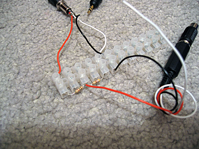
The TV contains a 75Ω resistor to ground on its composite video input. Two resistors are used on two PIC pins to form a voltage divider to produce the required output voltages (0V for sync, 0.3V for black and 1V for white). When the TV is disconnected the output of the circuit is 3.3V (the supply voltage, equivalent to a logic "high") as there's no load resistance to pull it to the correct 0.3V (a logic "low"). This can be used to periodically check whether a TV is connected and to switch between the LCD and TV output modes.
The above is rather vague, and I would recommend Rickard Gunée's article entitled How to generate video signals in software using PIC for more detailed information! The code for the demo can be downloaded from my website for those who are interested.
Update: I've updated my code to use the SPI peripheral in slave mode and use a timer and output compare unit to generate the clock signal. This regular clock signal produces pixels of identical sizes the new code can be downloaded here.
ATmega168 Snake
Tuesday, 24th November 2009
In addition to the Tetris game from the previous post, I've added an implementation of snake to the ATmega168 project.
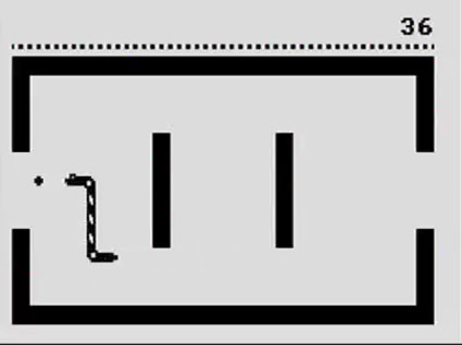
Either game can be selected from a menu that appears when the circuit is powered on. To exit menus I've added a second fire button; this allows you to step back to the main menu to pick a different game if need be. The source code and binary can be downloaded as before.
I've written a number of different Snake implementations in the past. The early versions used a single array to represent every cell that the snake's body lay in (head as the first element, tail as the last element) that I would manually shift every frame and resize when the snake ate some food. This gets slower and slower as the snake gets longer, which isn't very good. When I wrote a version for the TI-83+ calculator in BBC BASIC, I switched to using a ring buffer with a pointer to the head element and another to the tail element that would be shunted along every frame, unless the snake ate some food in which case the tail pointer would stay where it was.
As I have even less memory on the ATmega168, I went for a different tactic again; by using "pretty" graphics for the various parts of the snake in the tilemap, I didn't need to store the snake's path anywhere other than this tilemap. That is, if I wanted to advance the tail one unit, I merely need to look at the current tile graphic being used to represent the tail (which will be pointing up, down, left or right) and follow it along to the tile in front of it. By inspecting this tile, I can see if the snake turned a corner at that point or went straight ahead and so adjust the tail position and graphic accordingly.
void advance_tail(void) {
    // Find the current snake tail graphic.
    char tail = tvtext_buffer[tail_y * TVTEXT_BUFFER_WIDTH + tail_x];
    // Where is the body in relation to the tail?
    int8_t body_x = tail_x, body_y = tail_y;
    switch (tail) {
        case FONT_SNAKE_TAIL_UP:
            --body_y;
            break;
        case FONT_SNAKE_TAIL_DOWN:
            ++body_y;
            break;
        case FONT_SNAKE_TAIL_LEFT:
            --body_x;
            break;
        case FONT_SNAKE_TAIL_RIGHT:
            ++body_x;
            break;
    }
    // Ensure the body is on the buffer.
    if (body_x < WORLD_LEFT) body_x = WORLD_RIGHT;
    if (body_x > WORLD_RIGHT) body_x = WORLD_LEFT;
    if (body_y < WORLD_TOP) body_y = WORLD_BOTTOM;
    if (body_y > WORLD_BOTTOM) body_y = WORLD_TOP;
    // Find the current body graphic.
    char body = tvtext_buffer[body_y * TVTEXT_BUFFER_WIDTH + body_x];
    // Is it a bend? If so, we'll need to rotate the tail graphic.
    switch (body) {
        case FONT_SNAKE_BODY_DOWN_RIGHT:
            tail = (tail == FONT_SNAKE_TAIL_UP) ? FONT_SNAKE_TAIL_RIGHT : FONT_SNAKE_TAIL_DOWN;
            break;
        case FONT_SNAKE_BODY_DOWN_LEFT:
            tail = (tail == FONT_SNAKE_TAIL_UP) ? FONT_SNAKE_TAIL_LEFT : FONT_SNAKE_TAIL_DOWN;
            break;
        case FONT_SNAKE_BODY_UP_RIGHT:
            tail = (tail == FONT_SNAKE_TAIL_DOWN) ? FONT_SNAKE_TAIL_RIGHT : FONT_SNAKE_TAIL_UP;
            break;
        case FONT_SNAKE_BODY_UP_LEFT:
            tail = (tail == FONT_SNAKE_TAIL_DOWN) ? FONT_SNAKE_TAIL_LEFT : FONT_SNAKE_TAIL_UP;
            break;
    }
    // Erase the old tail.
    tvtext_buffer[tail_y * TVTEXT_BUFFER_WIDTH + tail_x] = tvtext_cleared;
    // Draw the new tail.
    tail_x = body_x;
    tail_y = body_y;
    tvtext_buffer[tail_y * TVTEXT_BUFFER_WIDTH + tail_x] = tail;
}
Similar code is used to advance the head and draw the correct tile behind it.
On an unrelated note, I've released a version of BBC BASIC that should run on the Nspire. The Nspire has an emulator on it to run applications for other calculators, but this emulator doesn't implement undocumented instructions. The TI-83+/TI-84+ BBC BASIC host interface makes use of the sl1 instruction, which shifts a register left one bit and sets the least significant bit to 1. Unfortunately, when this code is run on an Nspire it triggers a crash. Apparently the quick fix I've implemented seems to have done the trick, so unless I hear any further bug reports I'll release the latest version formally soon!
ATmega168 Tetris
Sunday, 22nd November 2009
The tvText library I discussed last entry allows you to display text on a PAL TV in black and white using a 20MHz ATmega168 and a pair of resistors. If this doesn't sound terribly exciting, it's probably because it isn't. However, if you bear some limitations in mind and change the font, you can use this text output as a more general tile-mapping system and use it for games that employ simple graphics.
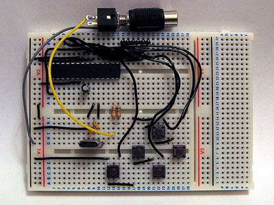
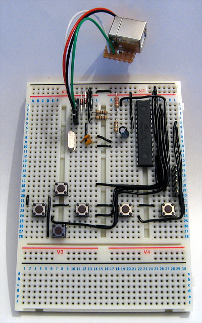
The new circuit, featuring five sloppily-wired input buttons.
I added five buttons to the test circuit — up, down, left, right and fire — to act as game input. This circuit is shown in the photograph above. I also added support for 8×8 characters alongside the existing 6×8 characters to the library, set as a compile-time option. This drops the number of characters per line from 32 to 24, but having square tiles makes producing graphics much easier. The reduction in size of the text buffer also frees up more of the precious 1KB of SRAM for the game!
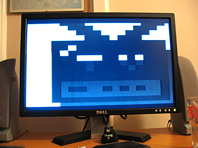
Even though it was always recommended as an excellent game for beginners to write, I don't believe I've ever written a Tetris clone before. Its simple block graphics makes it an ideal candidate for this system, and it always helps to work on a game that's fun to play. Armed with a Game Boy and a stopwatch I attempted to recreate a moderately faithful version of what is probably the most popular rendition of the game.
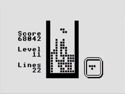
I think the result plays pretty well, but don't take my word for it — if you have an ATmega168 lying around, you can download the source and binaries here.
USB joypads and text on your TV courtesy of an ATmega168
Saturday, 14th November 2009
Nearly a month since my last update - my, how time flies when you're having fun (or a heavy workload).
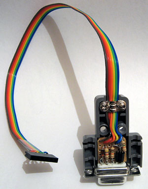
I ended up building myself a cheap and cheerful SI Prog programmer for AVR development. After installing the development tools, scanning through the documentation and writing the microcontroller equivalent of Hello, World (flashing an LED on and off) I needed to find a suitable project. The first one was getting to grips with V-USB, a software USB implementation for AVRs. All you need for this are a couple of I/O pins, a few configuration file changes to set your USB device's vendor ID, product ID and device class, and a few lines of C code to actually implement your device. I attached six tactile switches to an ATmega168 and made the most uncomfortable USB joypad I've ever used. I managed two levels of Sonic the Hedgehog before my thumbs admitted defeat, but it's nice to know that building USB devices is very easy with an AVR.
#include <avr/io.h>
#include <avr/interrupt.h>
#include <avr/wdt.h>
#include <util/delay.h>
#include <avr/sleep.h>

#include "usbdrv.h"

/* Joystick port bits */
#define JOY_1     (1<<0)
#define JOY_2     (1<<1)
#define JOY_UP    (1<<2)
#define JOY_DOWN  (1<<3)
#define JOY_LEFT  (1<<4)
#define JOY_RIGHT (1<<5)

/* USB HID report descriptor */
PROGMEM char usbHidReportDescriptor[USB_CFG_HID_REPORT_DESCRIPTOR_LENGTH] = {
    0x05, 0x01,        // USAGE_PAGE (Generic Desktop)
    0x09, 0x05,        // USAGE (Game Pad)
    0xa1, 0x01,        // COLLECTION (Application)
    0x09, 0x01,        //   USAGE (Pointer)
    0xa1, 0x00,        //   COLLECTION (Physical)
    0x09, 0x30,        //     USAGE (X)
    0x09, 0x31,        //     USAGE (Y)
    0x15, 0x00,        //   LOGICAL_MINIMUM (0)
    0x26, 0xff, 0x00,  //     LOGICAL_MAXIMUM (255)
    0x75, 0x08,        //   REPORT_SIZE (8)
    0x95, 0x02,        //   REPORT_COUNT (2)
    0x81, 0x02,        //   INPUT (Data,Var,Abs)
    0xc0,              // END_COLLECTION
    0x05, 0x09,        // USAGE_PAGE (Button)
    0x19, 0x01,        //   USAGE_MINIMUM (Button 1)
    0x29, 0x02,        //   USAGE_MAXIMUM (Button 2)
    0x15, 0x00,        //   LOGICAL_MINIMUM (0)
    0x25, 0x01,        //   LOGICAL_MAXIMUM (1)
    0x75, 0x01,        // REPORT_SIZE (1)
    0x95, 0x08,        // REPORT_COUNT (8)
    0x81, 0x02,        // INPUT (Data,Var,Abs)
    0xc0               // END_COLLECTION
};

static uchar reportBuffer[3];    /* Buffer for HID reports */
static uchar idleRate;           /* 4 ms units */

uchar usbFunctionSetup(uchar data[8]) {
    usbRequest_t  *rq = (void*)data;
    usbMsgPtr = reportBuffer;
    if ((rq->bmRequestType & USBRQ_TYPE_MASK) == USBRQ_TYPE_CLASS) {
        switch (rq->bRequest) {
            case USBRQ_HID_GET_REPORT:
                return sizeof(reportBuffer);
            case USBRQ_HID_GET_IDLE:
                usbMsgPtr = &idleRate;
                return 1;
            case USBRQ_HID_SET_IDLE:
                idleRate = rq->wValue.bytes[1];
                break;
        }
    }
    return 0;
}

ISR(TIMER0_OVF_vect) {

    /* Fetch input */
    uchar input = ~PINC;

    /* X-axis */
    switch (input & (JOY_LEFT | JOY_RIGHT)) {
        case JOY_LEFT:
            reportBuffer[0] = 0;
            break;
        case JOY_RIGHT:
            reportBuffer[0] = 255;
            break;
        default:
            reportBuffer[0] = 128;
            break;
    }

    /* Y-axis */
    switch (input & (JOY_UP | JOY_DOWN)) {
        case JOY_UP:
            reportBuffer[1] = 0;
            break;
        case JOY_DOWN:
            reportBuffer[1] = 255;
            break;
        default:
            reportBuffer[1] = 128;
            break;
    }

    /* Buttons */
    reportBuffer[2] = input & (JOY_1 | JOY_2);

    usbPoll();
    usbSetInterrupt(reportBuffer, sizeof(reportBuffer));
};

int main(void) {

    usbInit();              /* Initialise USB. */

    PORTC = 0b00111111;     /* Pull high PORTC0..PORTC5 */

    TCCR0B = 0b00000101;    /* CS2..CS0 = 101:  prescaler = /1024 */
    TIMSK0 |= (1 << TOIE0); /* Enable timer 0 overflow interrupt. */
    sei();                  /* Enable global interrupts. */

    for (;;) {
        /* Infinite loop */
    }
}
I should only really call usbSetInterrupt when a button or axis has changed, rather than every loop, but the above code works as is.
One thing that always bothers me when it comes to electronic projects is the difficulty of providing text output. LCDs are generally quite expensive and low resolution, and typically require a great many pins to drive them. Video display processor chips are difficult to find, and appear to require quite complex external circuitry (the best thing I've found thus far are some TMS9918 chips being sold as spares for MSX computers). Having briefly experimented with generating PAL video signals in software before, I thought I'd try the two-resistor approach to getting PAL video output on an ATmega168.
I had a hunt around and found AVGA, which is close to what I wanted - video output from an AVR using cheap hardware. However, it outputs RGB directly, and I don't own a TV or RGB converter so couldn't use that - all I have is a VGA box (accepting composite or S-Video input) and a TV capture card (also only accepting composite or S-Video input). AVGA does work with VGA monitors, but I'd like to keep the hardware interface simple - just two resistors, ideally.
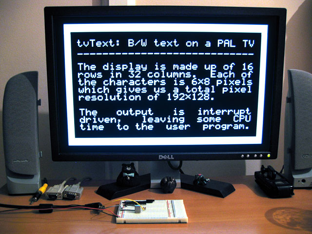
In the end, I ended up writing my own library. It currently has the following specifications:
- 32×16 characters: 512 bytes (half of the total SRAM on the ATmega168) are used to store the text buffer.
- Full 256 characters at a resolution of 6×8 pixels each.
- Total screen resolution: 192×128.
The library is interrupt-driven, and uses the sixteen-bit TIMER1 to schedule events. This means that the AVR is only busy generating video signals when it absolutely has to, leaving some CPU time to the user program. When outputting at full quality, the AVR appears to be capable of running user code at 3.3 MIPS, but by skipping alternate scanlines (each scanline is scanned twice anyway, so this mainly just makes the display appear darker) the AVR appears to be running user code at 9.9 MIPS. (I say "appears" as my calculation has been to execute a busy loop that would normally take one second on the AVR running at its normal 20 MIPS then seeing how long it takes with the video output driver enabled).
The above video demonstrates some of the currently rather limited features of the library. The text console handles a subset of the BBC Micro VDU commands - I'd like to support as many of its features as possible. The code behind the BASIC-like part of the demo is simply written like this:
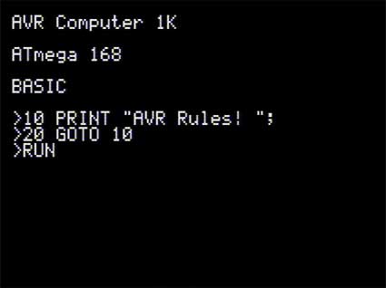
#include "tvtext/tvtext.h"

void type_string_P(const char* s) {
    char c;
    while ((c = pgm_read_byte(s++))) {
        tvtext_putc(c);
        delay_ms(100);
    }
}

int main(void) {

    tvtext_init();

    tvtext_clear();
    tvtext_puts_P(PSTR("AVR Computer 1K\r\n\nATmega 168\r\n\nBASIC\r\n\n>"));
    delay_ms(2000);
    type_string_P(PSTR("10 PRINT \"AVR Rules! \";\r\n"));
    tvtext_putc('>');
    delay_ms(500);
    type_string_P(PSTR("20 GOTO 10\r\n"));
    tvtext_putc('>');
    delay_ms(500);
    type_string_P(PSTR("RUN"));
    delay_ms(1000);
    tvtext_puts_P(PSTR("\r\n"));

    for (int i = 0; i <= 200; ++i) {
        tvtext_puts_P(PSTR("AVR Rules! "));
        delay_ms(20);
    }

    tvtext_puts_P(PSTR("\r\nEscape at line 10\r\n>"));
    delay_ms(1000);
    type_string_P(PSTR("CHAIN \"DEMO\""));
    delay_ms(1000);

    // ...

}
All of the high-level console code - text output, viewport scrolling, cursor positioning &c - has been written in C, so should be relatively easy to be customised. The output driver itself has been written in assembly as timing is critically important.
With a few more features and a bit of tidying up I hope that people would find this a useful library. I'd certainly like to get a blinking cursor working within the driver, and if I add support for a reduced 128-character version I could save quite a bit of ROM space and add support for "coloured" - inverted, that is - text. NTSC support would also be quite useful.
Brass 3 and software PAL
Wednesday, 14th November 2007
My work with the VDP in the Sega Master System made me more aware of how video signals are generated, so thought it would be an interesting exercise to try and generate them in software. This also gives me a chance to test Brass 3, by actively developing experimental programs.
I'm using a simple 2-bit DAC based on a voltage divider, using the values listed here. This way I can generate 0V (sync), ~0.3V (black), ~0.6V (grey) and 1V (white).
My first test was to output a horizontal sync pulse followed by black, grey, then white, counting clock cycles (based on a 6MHz CPU clock). That's 6 clock cycles per µs.
The fastest way to output data to hardware ports on the Z80 is the outi instruction, which loads a value from the address pointed to by hl, increments hl, decrements b and outputs the value to port c. This takes a rather whopping 16 clock cycles (directly outputting to an immediate port address takes 11 clock cycles, but the overhead comes from loading an immediate value into a which takes a further 7). The time spent creating the picture in PAL is 52µs, which is 312 clock cycles. That's 19.5 outi instructions, and by the time you've factored in the loop overhead that gives you a safe 18 pixel horizontal resolution - which is pretty terrible.
Even with this technique, in the best case scenario you output once every 16 clock cycles which gives you a maximum time resolution of 2.67µs. This is indeed a problem as vertical sync is achieved by transmitting two different types of sync pulse, made of either a 2µs sync followed by 30µs black (short) or 30µs sync followed by 2µs black (long). In my case I plumped for the easiest to time 4µs/28µs and hoped it would work.
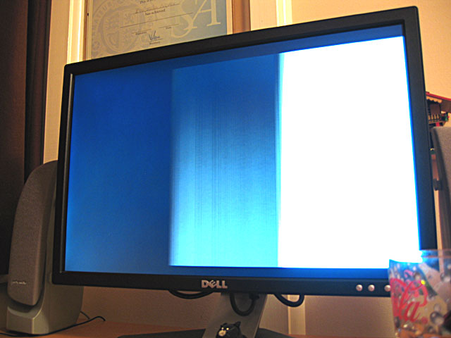
Anyhow, I made a small three-colour image for testing: ![]() .
.
Of course, as I need to output each scanline anyway I end up with a resolution of 304 lines, which gives me rather irregular pixels, so I just stretch the above image up to 20×304. Eagle-eyed readers would have noticed that the horizontal resolution is only 18 pixels, but somewhere in the development process I forgot how to count and so made the image two pixels too wide.
As you can see, it shows (the entire image is shunted to the right). TVs crop the first and last few scanlines (they aren't wasted, though, and can be used for Teletext) so that's why that's missing.  A widescreen monitor doesn't help the already heavily distorted pixels either, but it does (somewhat surprisingly) work.
With a TI-83+ SE (or higher) you have access to a much faster CPU (15MHz) and more accurate timing (crystal timers rather than an RC circuit that changes speed based on battery levels) as well as better interrupt control, so on an SE calculator you could get at least double the horizontal resolution and output correct vertical sync patterns. You also have better control over the timer interrupts, so you could probably drive hsync via a fixed interrupt, leaving you space to insert a game (the only code I had space for checks to see if the On key is held so you can quit the program - more clock cycle counting). I only have the old 6MHz calculator, though, so I'm pleased enough that it works at all, even if the results are useless!
Subscribe to an RSS feed that only contains items with the PAL tag.