Connecting an old receiver/amplifier to an HDMI television, apropos achieving surround sound
Sunday, 16th August 2020
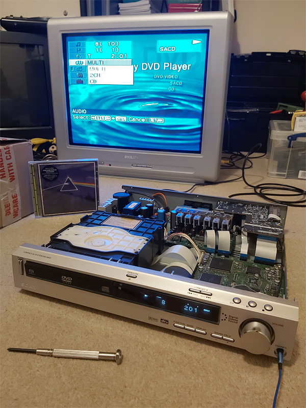
Now that the charity shops have reopened in the UK I enjoy hunting for good bargains and recently picked up a DAV-S400, a home cinema system originally sold back in 2002. I was not particularly interested in its DVD playback capabilities, especially as it only outputs composite video, but the integrated 5.1 surround sound amplifier and optical input made me think that I could use it to replace my current stereo amplifier for a better home cinema experience. The inclusion of SACD support was an added bonus as I'd bought myself a copy of The Dark Side of the Moon in that format back in 2004 and only been able to listen to it once, so if I couldn't get the home cinema side working at least the SACD part was self-contained and I'd be able to enjoy that.
This ended up being quite the learning project for me and I had to solve quite a few problems along the way. I'm still not entirely sure if I've found the best solutions in places but I thought I'd write this post in case it helps anyone else hooking up an old receiver/amplifier to a modern HDMI system!
The proposed setup
I watch most media using my Windows PC as a source. The PC is in one room and the TV is in another and long HDMI and USB cables run between both under the floorboards. An HDMI splitter is also used near the PC so it can drive its main monitor and the TV in the other room simultaneously.
I was previously running analogue stereo audio from the headphone socket of the TV to a stereo amplifier with a line level "super woofer" output that ran to a separate amplified subwoofer for 2.1 sound.
I knew that HDMI could carry digital audio, and both my monitor and TV have digital outputs. As the DAV-S400 has a digital input, I could just connect that to the digital output from the TV (instead of the headphone output) and in my naivety assumed that's all it would take to have glorious multichannel digital audio. Of course, things are rarely that easy…
My TV only has coaxial digital audio out via an RCA connector and the receiver has an optical input via a TOSLINK socket. Fortunately, my PC monitor has an optical output so I connected that to the receiver for the sake of testing. When I played media on my PC sound came out of the speakers, however only in stereo, even from 5.1 sources. What was going on?
Capabilities of S/PDIF
The digital output from the monitor/TV and the digital input of the amplifier operate with S/PDIF digital audio. This can carry two channels of uncompressed PCM audio for regular stereo. To carry 5.1 multichannel audio the data needs to be compressed using Dolby Digital or DTS. The DAV-S400 supports both, but you need to find a way to transfer that compressed signal to the receiver first.
Foiled by the EDID
Here is the biggest fly in the ointment! Extended Display Identification Data (EDID) is metadata that an HDMI display provides to describe what sort of video resolutions and sound formats it supports. All three of my HDMI devices (the HDMI splitter and both displays) report that they support two-channel PCM audio but nothing else.
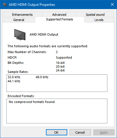
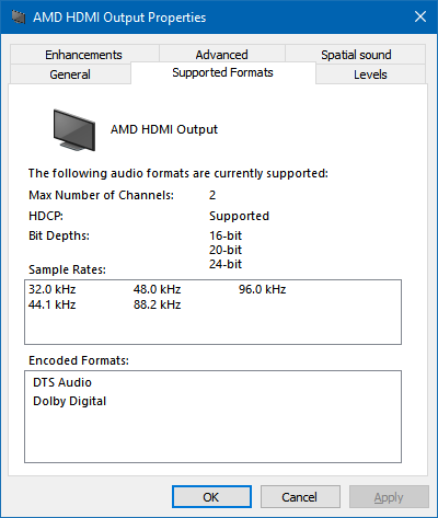
As a result, devices will only try to send stereo PCM audio to them and not Dolby Digital or DTS. If you have a sound card with an S/PDIF output you will notice that you can go in to its "Supported Formats" tab in Windows and tick which features the receiver supports – this is as the receiver can't tell the sound device which formats it supports automatically like an HDMI device can via its EDID. Unfortunately, Windows trusts the EDID and doesn't let you go in and enable support for features the display doesn't claim to provide. An easy solution here would be to just use my sound card's S/PDIF output but I didn't fancy taking the floorboards up again to run another cable…
A custom monitor driver to override the EDID
Fortunately you can create a custom monitor driver with a "fixed" EDID that advertises support for Dolby Digital and AC3 using a couple of easy tools.
The first piece of software you'll need to use is EnTech's Monitor Asset Manager – this will allow you to extract the current EDID to a file and will later let us turn the updated EDID back into an installable driver.
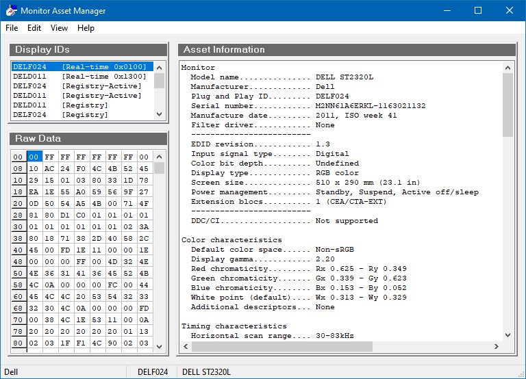
Run the software and find the monitor that is connected to the HDMI port that you are going to be outputting sound to from the list in the top left. In my case that's my HDMI splitter (which for some reason identifies itself as a DELL ST2320L). Save the EDID to a .bin file via the File→Save as menu item.
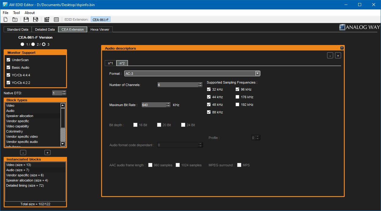
Now that you have your EDID data exported to a file, you'll need to edit it. A nice idiot-proof way to do so is with Analog Way's AW EDID Editor. Run the software and open the .bin file for the EDID file you just saved. Switch to the CEA Extension tab and you will probably see that it only reports support for stereo uncompressed PCM when you look at the "Audio" block.
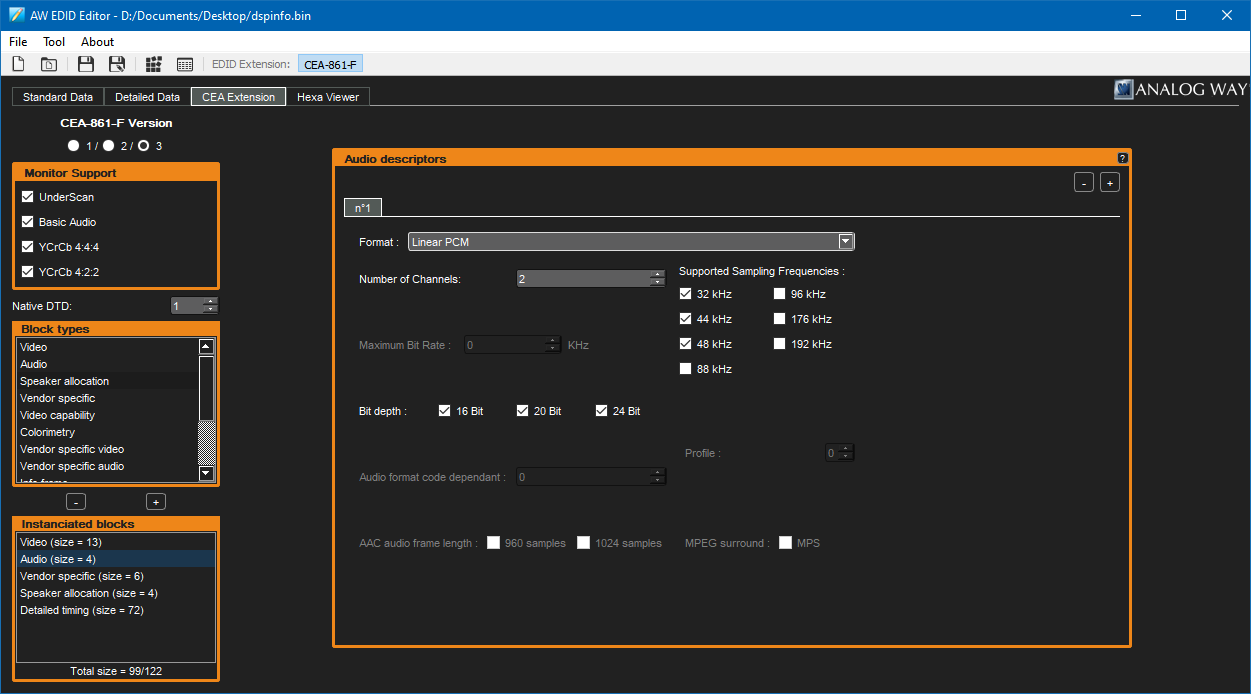
At this point, you can add audio descriptors according to the capabilities of your receiver. I'm not entirely sure what the best values to enter here are, especially when it comes to bitrate – as far as I'm aware DVDs usually use up to 448kbps for Dolby Digital AC-3 and up to 768kpbs for DTS but there's a more concrete limit of 640kbps for AC-3 and 1536kbps for DTS so these are the values I've used when setting up my EDID.

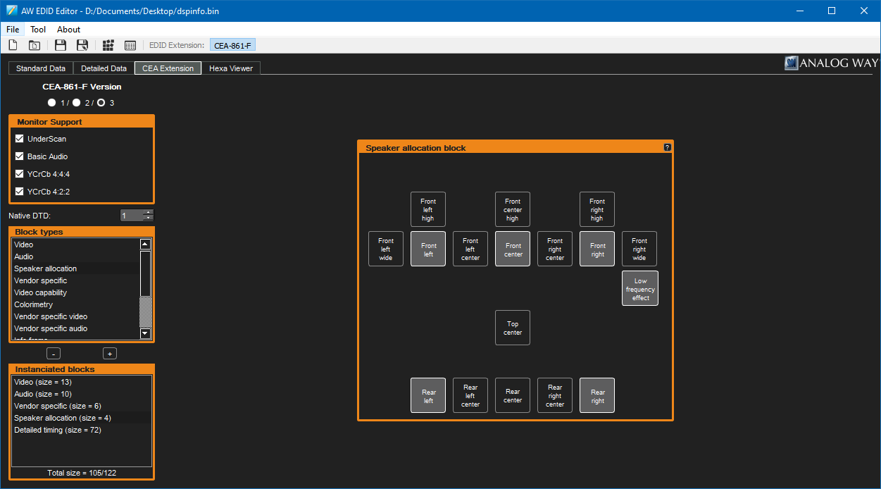
You can also use the "Speaker allocation" block to specify which speakers your device has attached – in my case I've set this up to match my 5.1 setup. Save the EDID at this point, and you're ready to create the custom monitor driver!
Go back to EnTech's Monitor Asset Manager and open the saved .bin file for your new EDID. Click File→Create INF and save the INF to create your new monitor driver. Easy!
What's less easy now is installing that driver on a modern 64-bit version of Windows, as the driver is unsigned and Windows will not let you install unsigned drivers normally. To save headaches at this point I'd recommend looking up how to enable the installation of unsigned drivers, but at the time of writing this is how it's done in Windows 10 (this will involve restarting your computer):
- Click Start→Power
- Hold Shift, then click "Restart".
- At the "Choose an option" screen, select "Troubleshoot".
- At the "Troubleshoot" screen, select "Advanced options".
- At the "Advanced options" screen, select "Start-up Settings".
- At the "Start-up Settings" screen, click "Restart".
- Once the computer has restarted, select the "Disable driver signature enforcement" option (F7).
When the computer has restarted, you should be able to install your unsigned monitor driver. To do this, go into Device Manager and find the entry for your HDMI device in the "Monitors" section.
- Right-click your device and select "Update driver".
- Select "Browse my computer for drivers".
- Click "Let me pick from a list of available drivers on my computer".
- Click the "Have Disk..." button.
- Browse for the monitor.inf file you created previously, then click OK.
- Select the EDID Override option that appears in the list and click "Next".
- Click "Install this driver software anyway" when prompted by the unsigned driver warning dialog box.
At this point, you will likely need to restart again but all being well after doing so you should now see that Dolby Digital and DTS Audio are now listed as supported encoded formats in the Sound control panel.
Passing through Dolby Digital and DTS without conversion to PCM
Getting Windows to believe that your receiver supports Dolby Digital and DTS over HDMI is the trickiest problem, but you still need to ensure that the compressed audio gets through every step of the way from the media to the receiver.
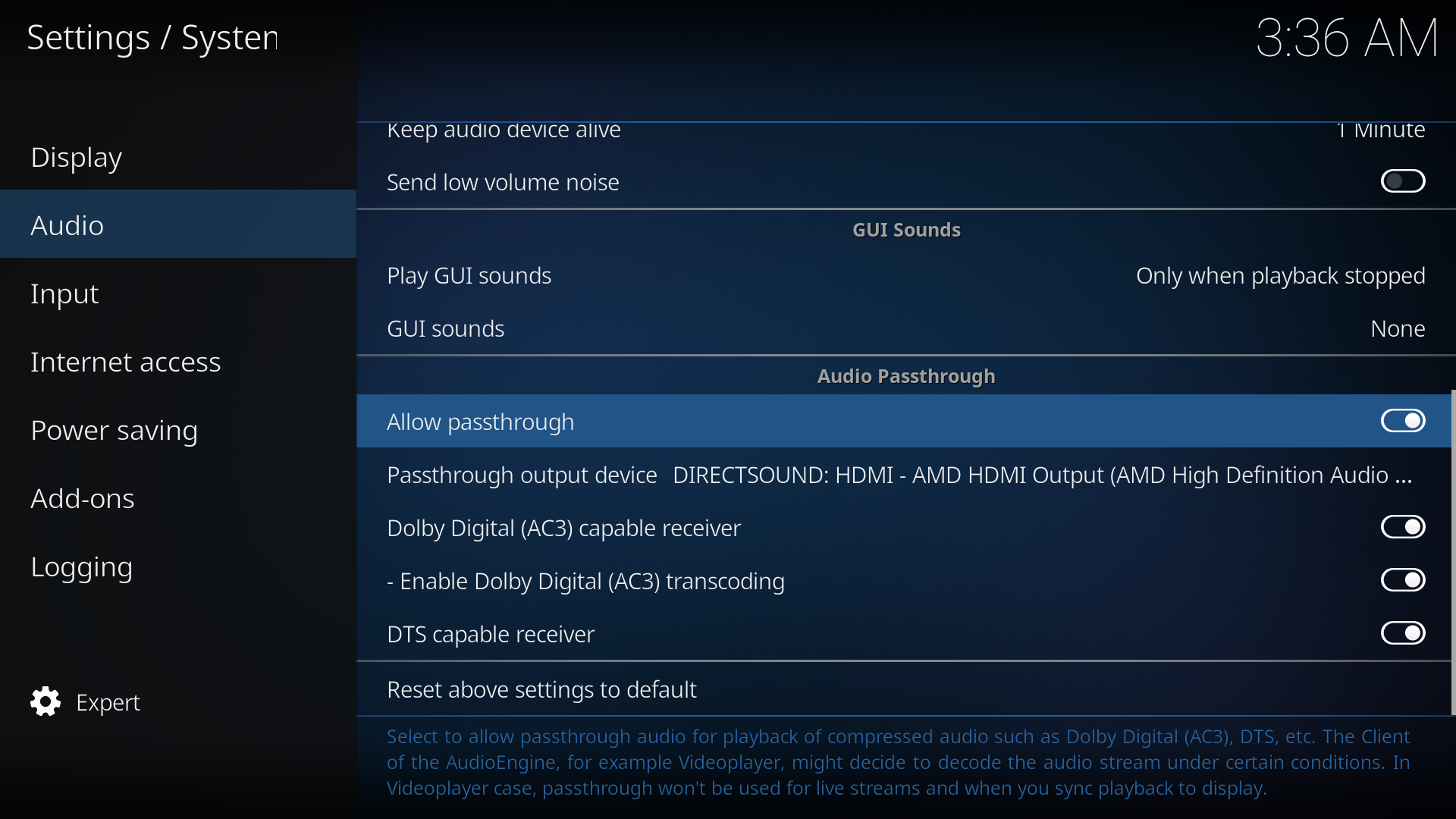
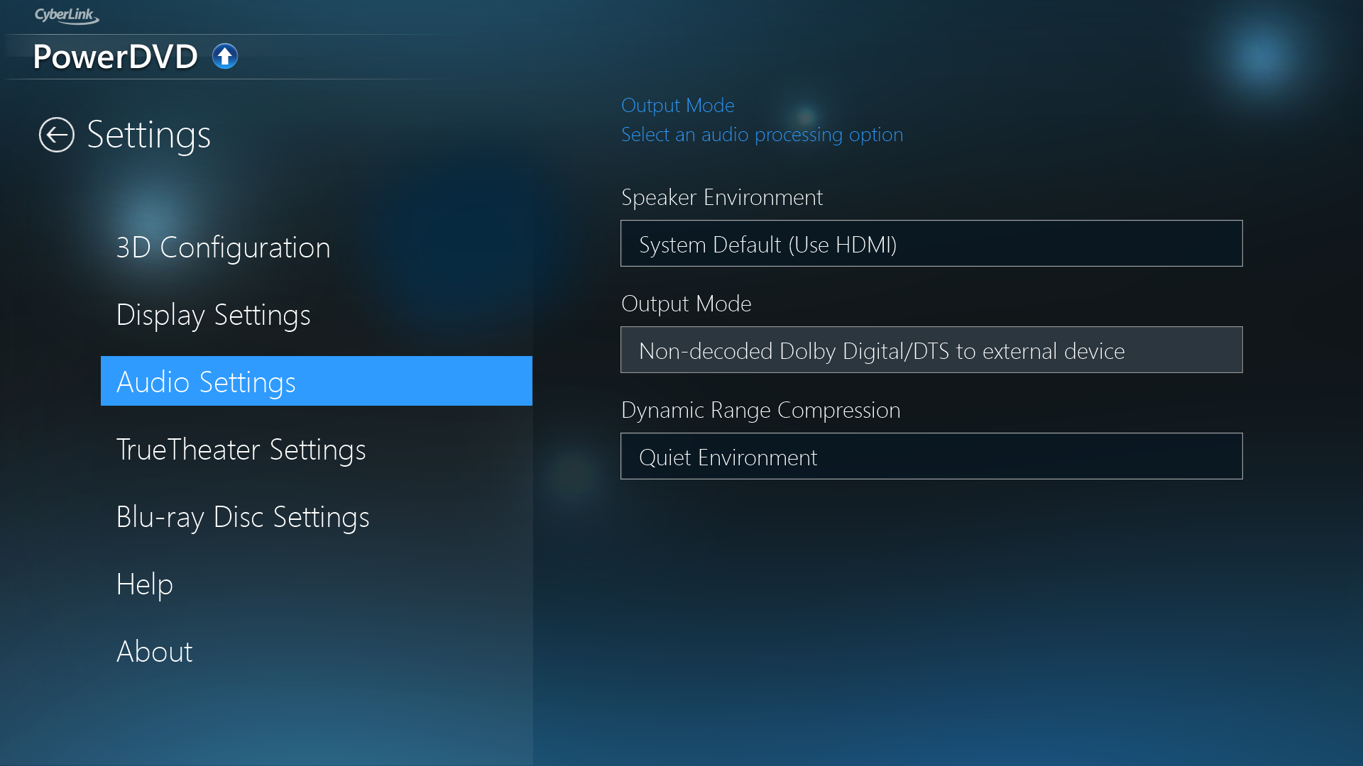
You will need to ensure that your media playback software is configured to pass through the audio directly rather than decoding it to PCM. If your software has an audio settings menu option, ensure that that is set to allow non-decoded audio to pass through.
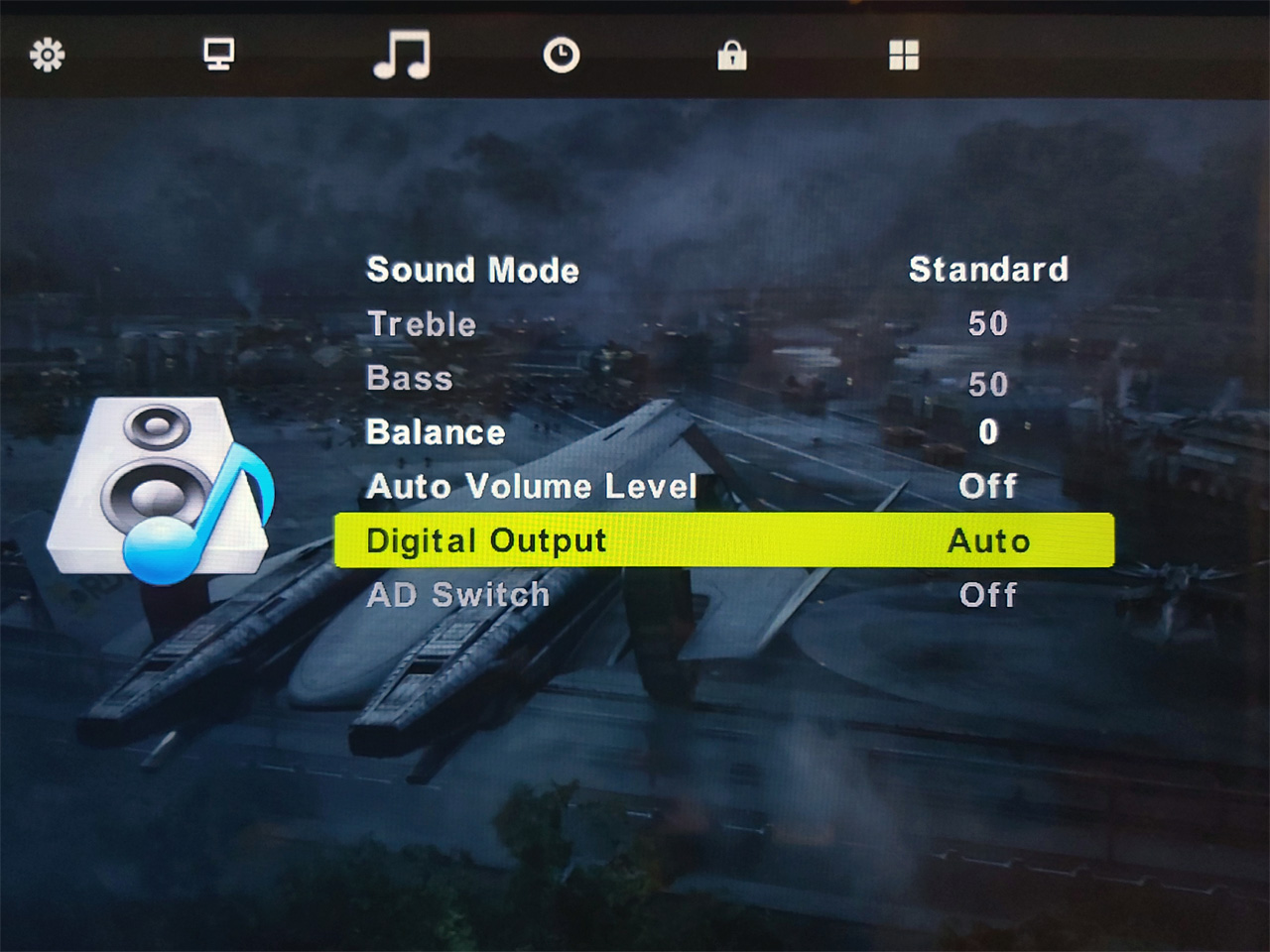
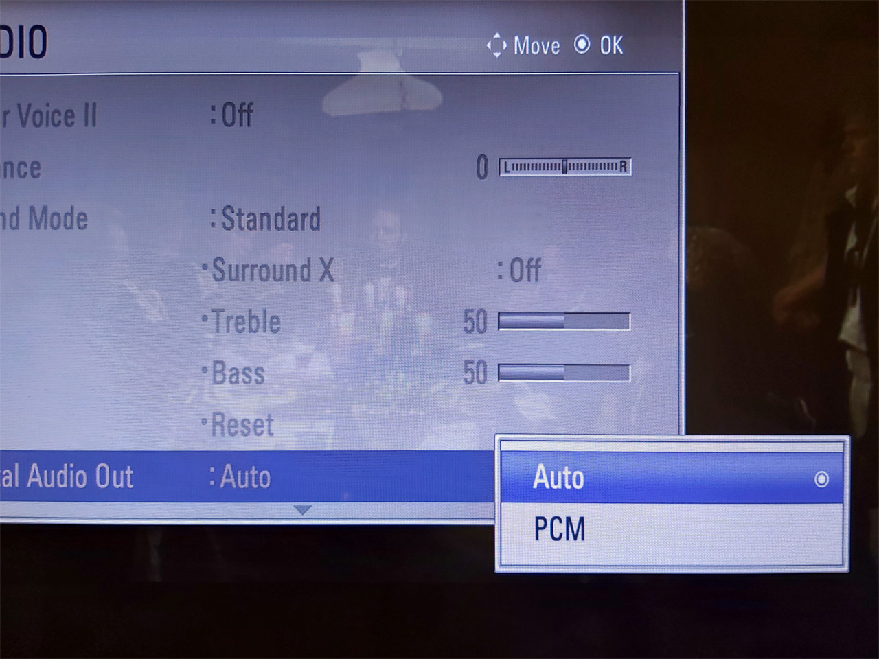
You will also need to ensure that your display is configured to pass through the audio without decoding it to PCM – check its sound menus for the relevant options, and change any settings to "Auto" or the appropriate equivalent instead of "PCM".
In my case I was testing with the receiver connected to my PC monitor via its optical output. Dolby Digital worked fine, however DTS was not working at all. I found that if I enabled the monitor's internal speaker it would output sound when fed Dolby Digital but not when fed DTS, however my TV would output sound when fed either. It seems that my PC monitor genuinely lacks support for DTS and won't even pass it out of the digital output port – fortunately when I acquired a coax to optical adaptor for my TV I found that it passed through DTS just fine!
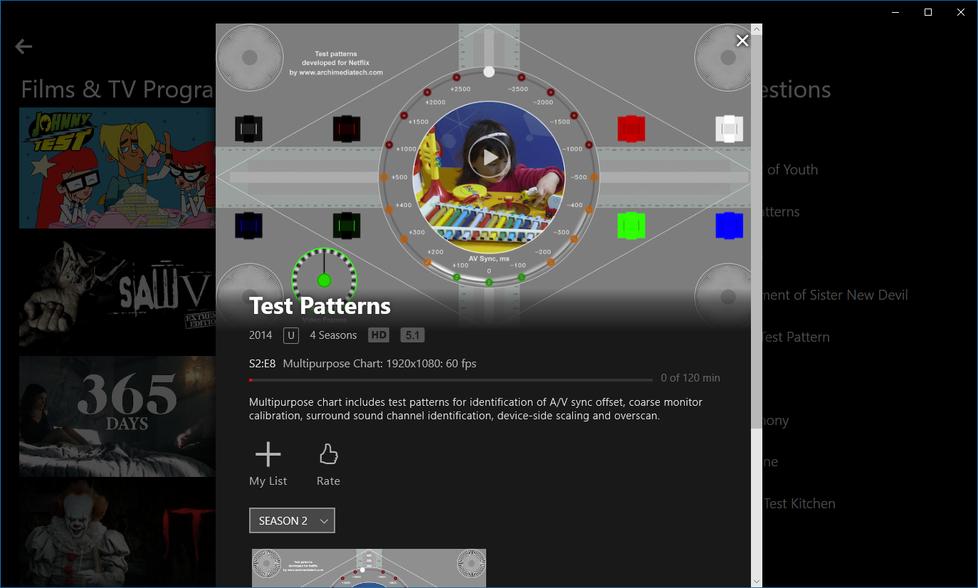
The Windows 10 application version of Netflix also supports 5.1 audio over Dolby Digital and didn't need any further configuration. If you search the library for "Test" there's a useful selection of test patterns that can be used to ensure your speakers are set up correctly.
Other notes
I have a separate Blu-ray player attached to my TV as my PC's video card displays corrupt video when decoding Blu-ray 3D unless I install very old versions of its drivers and I thought a separate Blu-ray player was an easier option than dual-booting into Windows Vista. Unfortunately, my Blu-ray player believes my TV's EDID and refuses to pass-through Dolby Digital or DTS over HDMI even when set to output "bitstream" audio. Fortunately it has a separate coaxial digital audio out that outputs Dolby Digital or DTS even when it's outputting PCM over HDMI but it does mean I need to add a switch box for the single digital input into the receiver which is slightly less elegant than running everything through the TV. There are standalone EDID spoofers that plug in between your device and the monitor that may be able to resolve this issue in the same way the custom PC driver did but these are not inexpensive so I have not been able to test this myself.
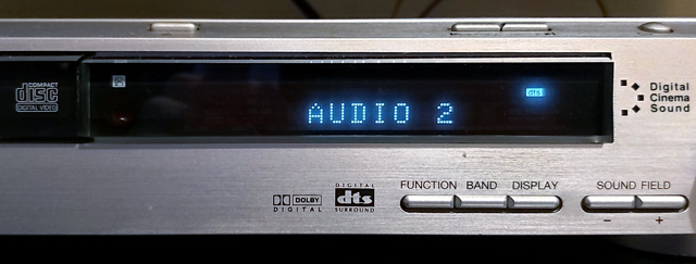
The DAV-S400 is extremely fussy about reading hybrid SACDs, and will often detect them as regular CDs. Ejecting and closing the tray persuades the machine to re-scan the disc, so if you have problems press the "DVD Display" button to ensure the OSD is visible and double-tap the eject button to quickly eject and close the tray until the indicator in the top right of the screen reads "SACD" instead of "CD".
If it does detect it as an SACD it will then play it absolutely flawlessly, the issue only seems to be with the initial format identification. I was able to improve the success rate with Dark Side of the Moon by carefully cleaning the drive lens, however I couldn't get Brothers in Arms to be detected at all until I went into the service menu and recalibrated the drive. You can do this by switching the machine on in DVD mode, holding the Stop+Display buttons on the unit together and rotating the volume wheel clockwise. From here go into "Drive Auto Adjustment". I initially tried calibrating with an SACD (labelled "LCD" in the menu) but this didn't help, so I tried the "All" menu option which prompts you to insert a single-layer DVD (DVD-SL), CD, then dual-layer DVD (DVD-DL). After this point it doesn't automatically prompt for an SACD so I left this in the default settings rather than calibrating and to my surprise found that Brothers in Arms now works (and, once detected, plays flawlessly). This inability to handle hybrid SACDs correctly seems to be a common flaw with Sony players of this vintage, unfortunately.
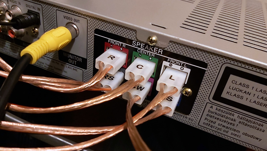
On a more practical note, I needed to find a way to attach my speakers to the amplifier, which had connectors that exposed a pair of pins around 6mm apart. Following a hunch I bought some Tamiya power connectors and found these to be a good fit once you cut off the retaining clip!
I did however find that a couple of the audio channels were intermittent and when I took the case lid off was surprised to see that one of the electrolytic capacitors on the amplifier board was barely held in by any solder at all and when I touched it it let out a big fat noisy spark! I resoldered it in along with all of the audio transformers, connectors and relays on the amplifier PCB which fortunately restored all audio channels back to their former glory.
All in all this has been quite a learning experience, though having now watched Terminator 2 and Mad Max: Fury Road with 5.1 surround sound I can definitely say it was worth it.
Repairing damaged plastic pegs
Friday, 4th October 2019
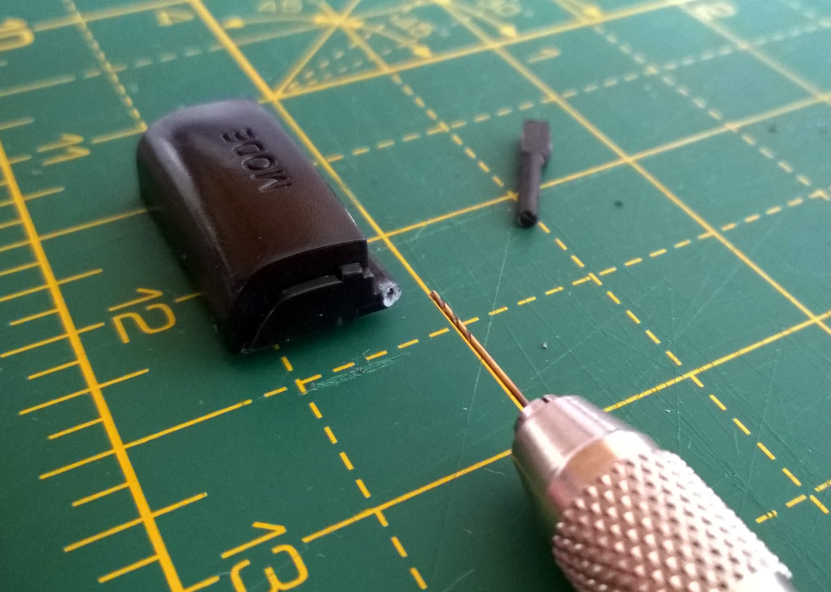
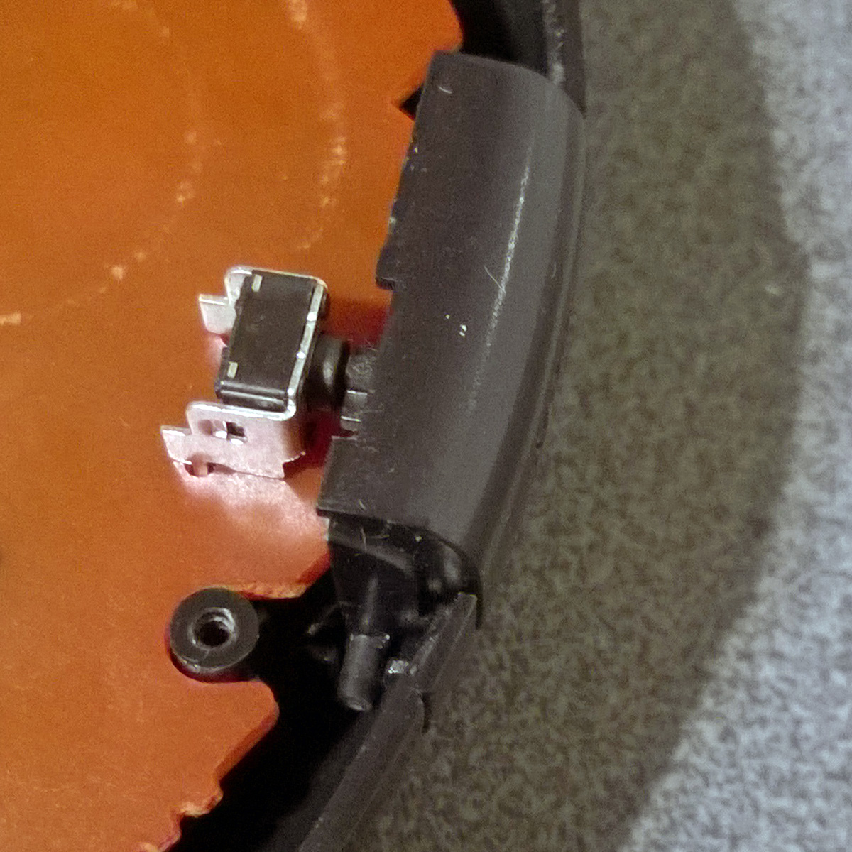
It's not uncommon for parts of old electronic devices to have damaged plastic pegs, like the one in this photo:
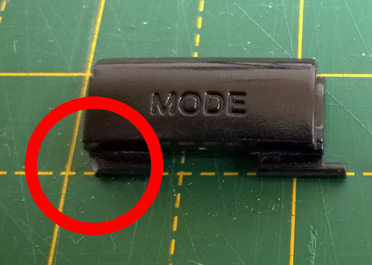
If you still have the snapped off plastic peg you may be able to glue it back on, but this can leave a weakened part that doesn't hold up very well. In other cases you might have lost the part entirely. This happened to me recently with the purchase of a six-button Mega Drive control pad. I ordered it from CeX's website and so couldn't see what condition it would be in until it arrived in the post. Unfortunately, it arrived in a filthy condition with a d-pad that only worked if you pressed the buttons very firmly and a non-functioning Mode button. I took it apart and was able to get the d-pad working again by cleaning the contacts. Whilst I left the rest of the plastic parts soaking in the sink to try to remove as much of the encrusted grime as possible I turned my attention to the faulty Mode button.
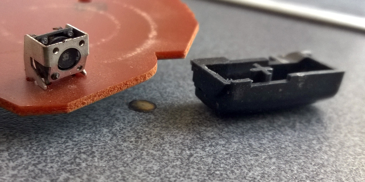
At some point the button must have been pushed in too firmly, damaging the tactile switch on the main board - the metal casing was bent and the plastic switch body had separated from it with the metal diaphragm that closes the contacts falling out. I've seen the same thing happen to some Sega Saturn control pads and fortunately had some spares in my parts bin so was able to swap that out easily. However, the pressure had snapped one of the plastic pegs of the Mode button off and it was nowhere to be found, so I needed to construct a replacement.
Fortunately, I have some scrap plastic parts from cutting out holes in plastic enclosures. In my case I needed to make a new peg that was 1.8mm in diameter, and had some 2mm sheet to use for this purpose. If I didn't have this then I could have gone online to buy a small 2mm thick sheet of ABS, but I prefer to recycle where possible!

The first thing to do was to get a piece of plastic that was roughly the right size, so I cut a length with a cross-section of 2×2mm. To cut the plastic I scored it with a knife and then snapped it by gripping the short part with a pair of pliers and bending the longer part away from the score line.
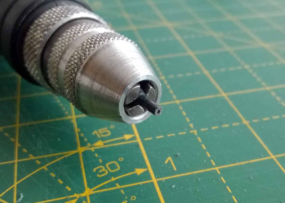
As the plastic peg needs to rotate in its slot inside the control pad it needs a round cross-section rather than a square one. To shape the peg into a rough cylinder I mounted it in the chuck of a rotary tool, as pictured above.
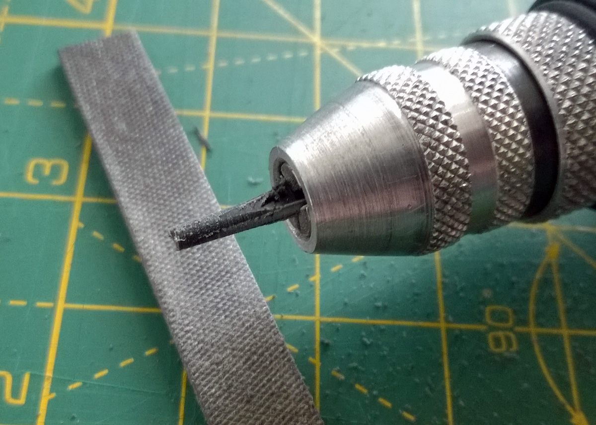
The rotary tool was then switched on and the plastic part held against a file. The photo above shows the start of this process with the peg beginning to take form. You need to work somewhat slowly with plastic as it gets hot when filing, cutting or drilling and if you let the heat build up it can melt and bend or gum up your tools. In my case I only used the file for a short period at a time before giving the piece time to cool back down. If I had been able to use my variable-speed rotary tool I could have set it to a lower speed to reduce the heat however the collet chuck on that tool wouldn't have been able to grip the work piece.
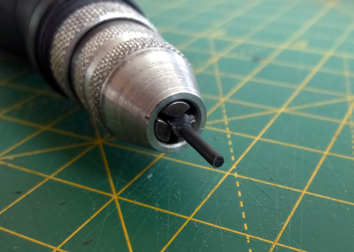
It doesn't take very long to get a nice round profile on the peg, though, even when working slowly (it's only a small piece, after all!) I carried on working it until I measured the 1.8mm diameter I was aiming for.
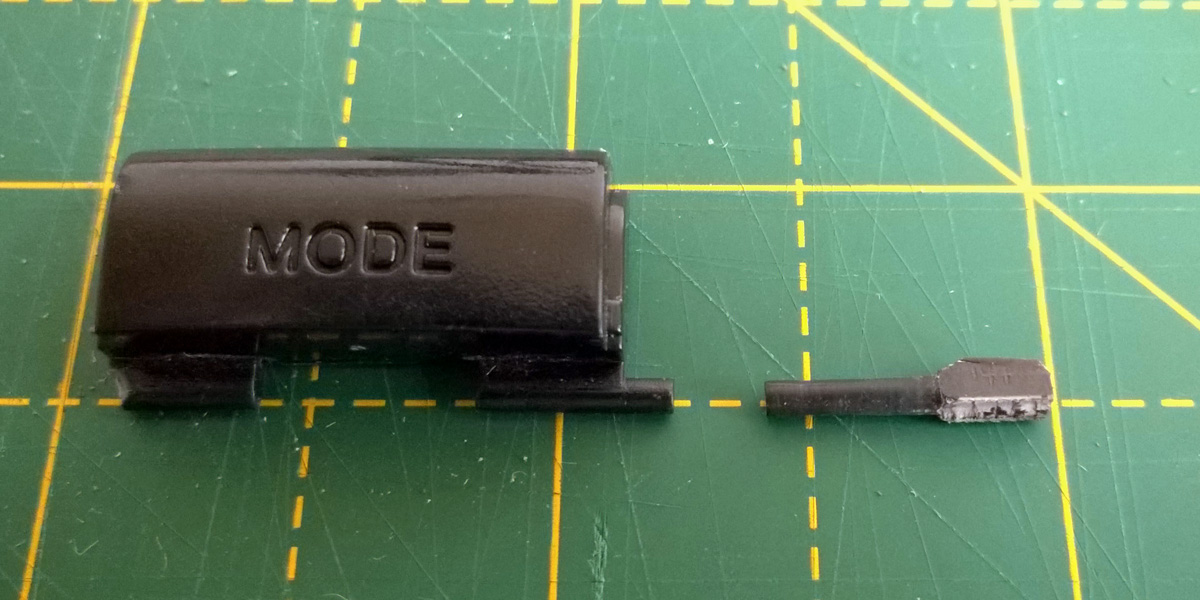
The above photo shows a size comparison between the new peg and the intact one on the Mode button. I've left the piece long (with the rough ending as a "handle") to make it easier to work with until it's time to fix it in place rather than cutting it to length straight away.
How to attach the new peg to the damaged button is the next issue to deal with. The rough surface of the snapped area of the button would make gluing difficult, though it could be filed flat to provide an easier surface to work with. My preferred technique, however, is to fix the new plastic peg with a metal pin made from a paper clip. This involves drilling narrow holes in the old button and the new peg to fit the metal pin through.
A pin vice is an invaluable tool for fine drilling work like this. I started with a very small drill bit to make the initial hole, being very careful to ensure I was drilling straight and in a well-centred location. This is something that needs to be taken slowly, especially on the original part. Once I had a pilot hole in the right place I switched to a larger drill bit that would drill a hole that the paper clip could fit into.
Starting the hole in the plastic peg might be easier by spinning the piece in your rotary tool and then bringing the stationary drill bit up to the end of it. As before be very careful about melting the plastic as once the hole is drilled the plastic is even thinner and will melt more easily – the peg is much shorter in the above photo than it was in previous photos as I accidentally melted it when I tried to drill all the way through in the rotary tool. I had to cut off the melted and distorted part to start again, only starting the hole in the rotary tool this time and then drilling the rest of the way slowly by hand. It's a good thing there was plenty of excess material!
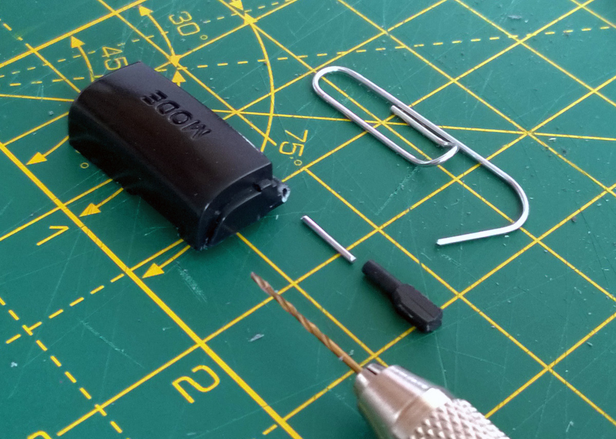
The above photo shows the short length of paper clip that has been cut to connect the two plastic parts. Using a piece of wire like this should provide a lot of strength to the join – my experiences of gluing plastic to plastic have been very mixed, depending on the glue and plastic involved.
The parts in this case are all glued together with superglue and it seems to hold together quite well. The replacement peg was first cut to length before being glued. I coated one end of the paper clip rod in glue before pushing it into the hole on the button, then added glue to the other end and slid the new peg on. The end of the peg had a slightly protruding piece of the paper clip rod, so it was filed flush once the glue had set.
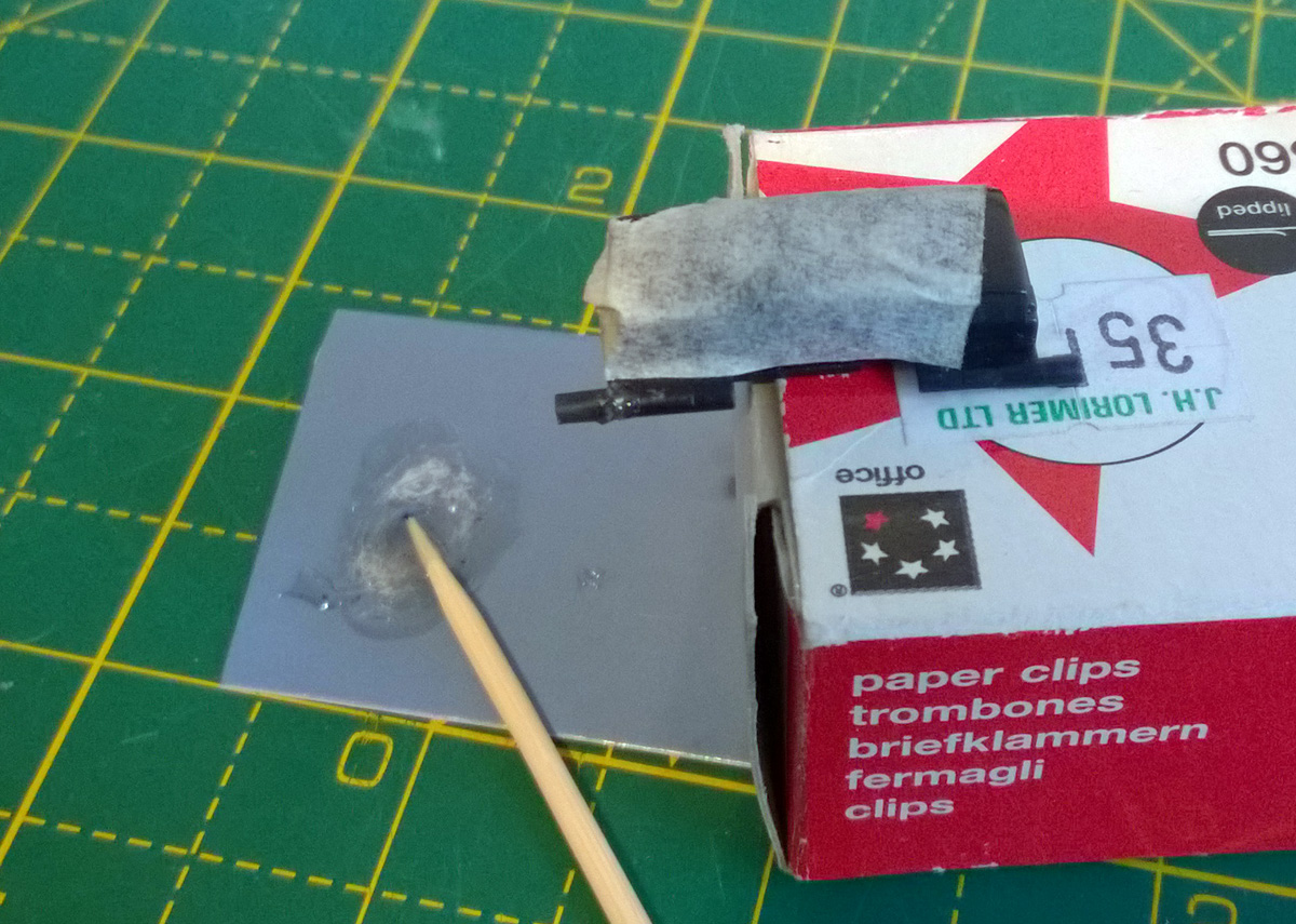
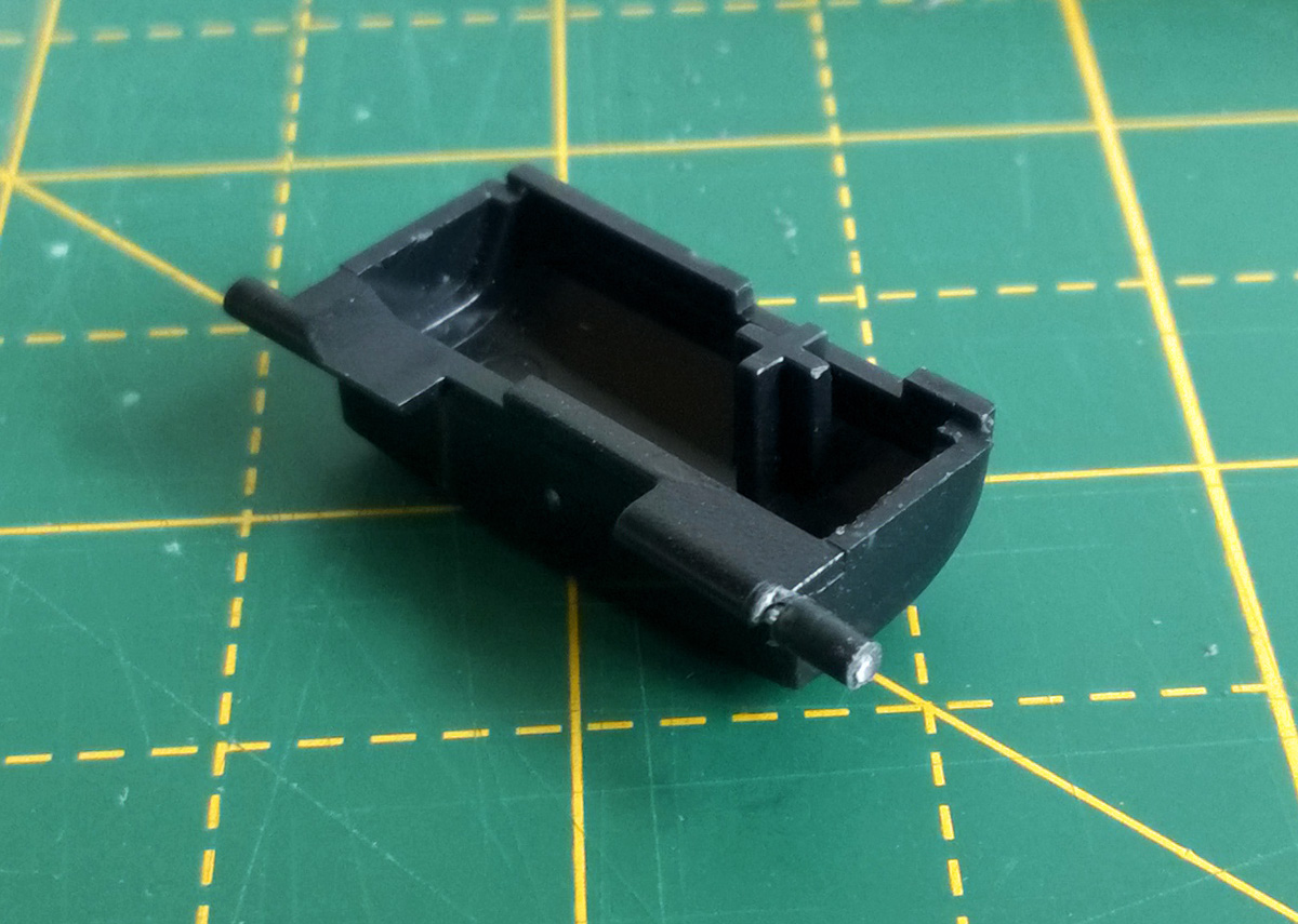
The uneven break still left a small gap in the join between the new peg and the Mode button body, so I filled it with a small amount of two-part epoxy resin. I used a toothpick to transfer a small amount of the mixed epoxy resin into the gap. This is always a bit messy so I protected the main button surface with masking tape. I also tidied up any "blobbiness" or glue that had otherwise run to undesired areas with a sharp knife before the epoxy had fully cured.
The button now sits properly in place inside the control pad and swings freely as it should. I could of course have just returned the control pad for a refund considering its condition but in spite of its problems it was still a well-priced item and I'm not sure they would have bothered to repair it. At least I know this way it'll be appreciated in its second life!
Fixing the Dreamcast Race Controller's dead zone with a simple microcontroller circuit
Tuesday, 21st May 2019
I recently bought myself a Race Controller wheel for the Sega Dreamcast and was a little disappointed with the way that it performed. I had read reviews online before buying it and some did mention that it didn't handle particularly well but others did mention that it was about the best controller available for the system so I didn't feel it was too risky a purchase.
The issues I have with the wheel stem from its excessively large dead zone – you need to turn the wheel quite far before your car starts to turn, making it feel sluggish and unresponsive.
Fortunately, the wheel hardware is very simple internally – a 100KΩ potentiometer is used to detect the wheel's position and it outputs an analogue voltage to the controller PCB. We can take advantage of that to insert our own circuit between the potentiometer and controller PCB to sample the wheel position, add an large offset to it to push it outside the dead zone and then output that corrected voltage to the stock PCB. This will then cancel out the offset as part of the large dead zone before sending the position to the console.
The video above goes into more detail about how this circuit works as well as illustrating the problem with the stock dead zone. For more information and to download the code and circuit diagram please see the De-Dead Zone product page.
Repairing a PlayStation controller to USB adaptor
Saturday, 20th April 2013
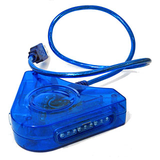
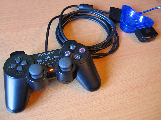
I recently purchased an inexpensive PlayStation controller USB adaptor for my PC. Several reviews confirmed that it was compatible with the controller's analogue joysticks so I thought it would be what I was after. Life is rarely that easy with cheap electronics, unfortunately!
When it arrived I plugged it in and Windows installed the appropriate HID drivers for it automatically, but as much as I waggled the joysticks on a connected DualShock 2 controller the axis preview in Control Panel remained resolutely in the zero position. PlayStation controllers have an "Analog" button that can be pressed to toggle between digital and analogue modes, but any attempts to press this resulted in the "Analog" light briefly flashing before immediately switching off again.
Thinking it may be a driver issue I tried to install the drivers from the mini CD that had been included with the adaptor. My PC could not read the disc (it appeared to be scratched, and was not very well protected in postage) so I hunted around online until I found a package that worked using the device's USB ID (VID_0810&PID_0001). This enabled the controller's rumble/vibration feature, but I still couldn't get analogue input to work. Thinking that if one driver package could add vibration support, another might add analogue support I contacted the Amazon seller to ask them if they could send me a copy of the correct drivers - they instead chose to send me a whole other unit in the post.
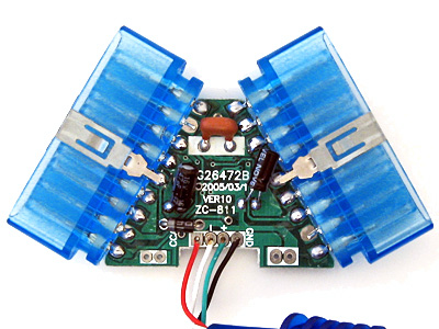
In the meantime, I experimented with another controller plugged into the adaptor. I was surprised to find that with two controllers plugged in at once I could enable analogue mode on one of the controllers. This made me think there could be a power issue - the second controller increased the capacitance across the power supply, which would make it more resilient to voltage spikes and reduce ripple that could be causing the controller to reset out of analogue mode. This was further confirmed by plugging the adaptor with a single controller into a powered USB hub - in this scenario the controller would only leave analogue mode when vibrating. I checked the power supply pins on the controller ports and was very surprised to see that there was apparently nothing connected to pin 5, which is supposed to deliver +5V to the controllers. At this point I decided to dismantle the adaptor to see what was going on.
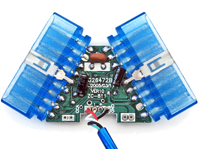
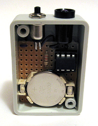
On the inside of the adaptor I could see that several components had been omitted. This could be to blame on cost-cutting measures (e.g. the LEDs D1 and D2 which are purely cosmetic) but the removal of D3 puzzled me the most - this diode is connected between USB VCC and the controller port pin 5, and is presumably responsible for providing power to the connected controller. I put this down to an oversight at the factory, and soldered a 1N4001 rectifier diode in the marked place.
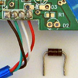
The above image shows a close-up of the place the missing diode should appear - D3 is indicated by a silk-screened diode symbol. Unsurprisingly the 1N4001 silicon diode has far superior characteristics to the silk-screen diode it replaced.
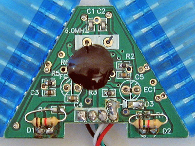
With the diode in place both controller ports started working flawlessly, even allowing me to use a wireless Guitar Hero controller receiver (though not the whammy bar - Guitar Hero controllers lack the "Analog" button to manually enable the analogue mode and instead rely on the PlayStation to enable it via software). Whilst I had the soldering iron out I thought I should add the missing LEDs, once again using the existing markings to establish the correct polarity:
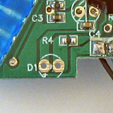
If the markings are unclear, the anode (+) is always to the left when viewing the bottom of the circuit board when the other markings are upright.
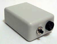
As the enclosure is blue and I seem to remember some fuss being made of the PlayStation 2's blue LED when it first came out I opted to use two blue LEDs with 1K5 resistors. I do not have any surface-mount resistors but through-hole ones fit quite easily though they can be a little fiddly to solder down.
When the replacement adaptor arrived in the post I was surprised to see that (once again) the diode D3 was missing and it demonstrated the same problems as the other one I'd fixed. I find it unlikely that the same mistake could be made twice, so this seems to be a genuine cost-cutting measure. Microcontroller I/O pins often have an internal protection diode between them and the positive power supply, which is how I assume the circuit works at all when the controllers are left unpowered - a small amount of current flows from the I/O (data) pins to the positive rail via these protection diodes, which is just enough to let the controller work in digital mode but once they draw more current (e.g. when sampling analogue inputs or driving the vibration motors) the voltage droops far enough for the controller to reset and leave analogue mode.
With these fixes in place I now have two working PlayStation USB adaptors for the price of one (and two 1N4001 diodes). I'm still rather perplexed by why there's such a blatent flaw in the hardware, but it is at least an easy fix which is why I've written it up. In summary: if your cheap PlayStation to USB adaptor ("Twin USB Vibration Gamepad", "Twin USB Joystick") is not working correctly, unscrew it and see if D3 is missing. If it is, solder a 1N4001 or similar diode between the two holes left for that purpose.
Ejecting discs from a damaged camcorder with a remote control
Tuesday, 29th December 2009
I hope that those of you who celebrate it had a good Christmas break and will have an excellent new year!
I recently attempted to repair a DVD camcorder that had been dropped; the eject button no longer worked, though the disc could be ejected by connecting to camera to a PC, right-clicking the DVD drive that subsequently appears in Explorer, then selecting Eject.
I started by removing all of the screws around the affected area, but the plastic casing remained strongly held together by some mysterious internal force. I removed more and more screws, but it soon became apparent that the only way to get into the camera would be to force it open – not being my camera, I didn't feel comfortable doing so, as the rest of the camera worked well and I didn't want to damage any fragile internal mechanisms. I couldn't find any dismantling guides online, so gave up on the idea of fixing the button.
Fortunately, I own the same model of camcorder – a Panasonic VDR-D250 – myself. With my interest in infrared remote controls I had previously found information about the Panasonic protocol it uses. The supplied remote control only has a few simple buttons on it (no eject button, sadly), but I reckoned that the camcorder may accept a number of other commands that the stock remote didn't include.
I started by modifying a universal remote control program for the TI-83+ that I had previous written to allow me to send specific commands to the camcorder, then ran through all of the possible command IDs, noting down those that appeared to have some effect. Eventually I had a pretty decent list, albeit one with quite a few gaps in it. Fortunately, I had found the Eject button code, along with codes to switch mode (which is done on the camera by rotating a mode dial), one that powers the camcorder off, another that appears to restart the camera and another one that resets all settings (not so useful, that one).
Having found the eject code, I set about building a dedicated remote control. I picked the ATtiny13 microcontroller as a base, as that's a more than capable microcontroller with its 9.6MHz internal clock, 1KB program memory, 64 bytes SRAM and 3V operation.
I was a bit surprised to see that AVR-GCC supports the ATtiny13, and whilst C may seem overkill for such a project I'll gladly take advantage of anything that makes my life easier. 
// Requisite header files.
#include <avr/io.h>
#include <util/delay.h>

// Frequency of the IR carrier signal (Hertz).
#define F_IR_CARRIER (37000)

// Timing of the data bits (microseconds).
#define T_DX_MARK   (440)
#define T_D0_SPACE  (440)
#define T_D1_SPACE (1310)

// Timing of the lead-in and lead-out bits (microseconds).
#define T_LEAD_IN_MARK    (3500)
#define T_LEAD_IN_SPACE   (1750)
#define T_LEAD_OUT_MARK    (440)
#define T_LEAD_OUT_SPACE (74000)

// Commands definitions.
#define OEM_DEVICE_1_CODE         (2)
#define OEM_DEVICE_2_CODE        (32)
#define CAMCORDER_DEVICE_ID     (112)
#define CAMCORDER_SUB_DEVICE_ID  (40)
#define CAMCORDER_COMMAND_EJECT   (1)

// Transmits a single unformatted byte.
void panasonic_send_byte(uint8_t value) {
    // Send eight data bits.
    for (uint8_t bit = 0; bit < 8; ++bit, value >>= 1) {
        // Send the mark/burst.
        DDRB |= _BV(1);
        _delay_us(T_DX_MARK);
        // Send the space.
        DDRB &= (uint8_t)~_BV(1);
        _delay_us(T_D0_SPACE);
        // Extend the space if it's a "1" data bit.
        if (value & (uint8_t)1) {
            _delay_us(T_D1_SPACE - T_D0_SPACE);
        }
    }
}

// Transmits a formatted command packet to the IR device.
void panasonic_send_command(uint8_t oem_device_code_1, uint8_t oem_device_code_2, uint8_t device_code, uint8_t sub_device_code, uint8_t command) {
    // Send the lead in.
    DDRB |= _BV(1);
    _delay_us(T_LEAD_IN_MARK);
    DDRB &= (uint8_t)~_BV(1);
    _delay_us(T_LEAD_IN_SPACE);

    // Send the five command bytes.
    panasonic_send_byte(oem_device_code_1);
    panasonic_send_byte(oem_device_code_2);
    panasonic_send_byte(device_code);
    panasonic_send_byte(sub_device_code);
    panasonic_send_byte(command);

    // Send the checksum.
    panasonic_send_byte(device_code ^ sub_device_code ^ command);

    // Send the lead out.
    DDRB |= _BV(1);
    _delay_us(T_LEAD_OUT_MARK);
    DDRB &= (uint8_t)~_BV(1);
    _delay_us(T_LEAD_OUT_SPACE);
}

// Main program entry point.
int main(void) {

    TCCR0A |= _BV(COM0B0) | _BV(WGM01);     // Toggle OC0B when on CTC reload. Use CTC mode.
    TCCR0B |= _BV(CS00);                    // Set clock source to CPU clock/1.
    OCR0A = (F_CPU / F_IR_CARRIER / 2) - 1; // Set the CTC reload value to generate an IR signal at the correct carrier frequency.

    // Send the "eject" command ad infinitum.
    for(;;) {
        panasonic_send_command(OEM_DEVICE_1_CODE, OEM_DEVICE_2_CODE, CAMCORDER_DEVICE_ID, CAMCORDER_SUB_DEVICE_ID, CAMCORDER_COMMAND_EJECT);
    }
}
The code is about as simple as the circuit. IR signals are transmitted as carefully timed bursts of a particular carrier frequency (37kHz in this case). For example, to send a "0" bit 440μS of this 37kHz signal are sent followed by 440μS of silence. To send a "1" bit, 440μS of carrier signal are sent as before, but a 1310μS period of silence follows it.
The AVR's timer is used to generate a ~37kHz carrier signal. The timer is an eight-bit counter that counts up at a user-defined rate (in my case I've chosen to increment the counter by one every CPU clock cycle). I've configured it to invert the output level of pin OC0B and reset every time it hits a particular value. By setting whether this pin is an output or an input the output of a burst of 37kHz IR signal or silence can be selected. Simple delay loops, generated with the helper function _delay_us, are used to time the transmission of data bits.
The final step was to assemble the circuit on stripboard and install it in a smallish project box. I've put the switch adjacent to the LED for two reasons; to conserve space and to protect it a little from accidentally being pressed by the protruding LED bezel.
Building a single-button remote control is a relatively straightforward affair, so whilst the above code has a very specific purpose it should be easy enough to modify it to control other devices.
Subscribe to an RSS feed that only contains items with the Repairs tag.