Integrating the dsPIC33 VDC with the Z80 computer
Saturday, 31st July 2010
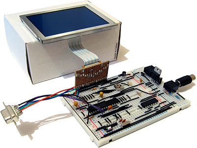
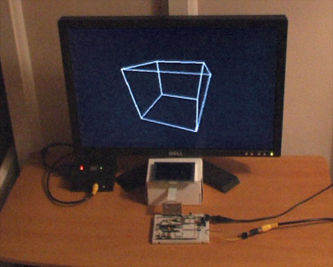
The ultimate goal for the video display controller module I have been working on is to drive the display in my Z80 computer project. As I have now got a pretty good set of features I thought it would be a good idea to join the two projects together.
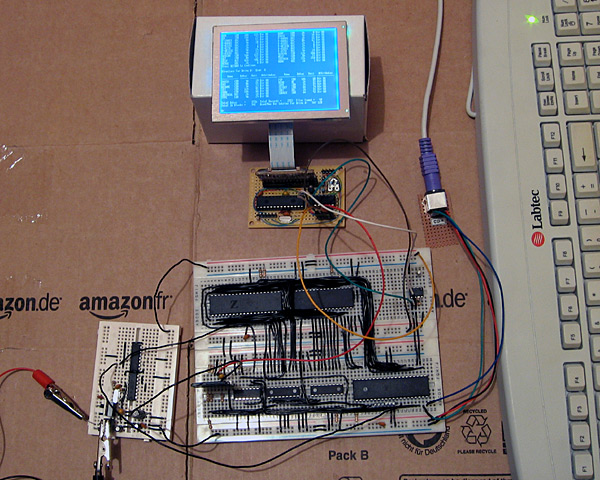
The big board in the lower middle of the above photograph is the main body of the computer, including the Z80, its RAM, the ATmega644P that is used to handle I/O, an SD card for storage and a DS1307 real-time clock. The small board in the bottom left of the photo is the power supply (supplying both 5V and 3.3V) and clock generator (providing a 20MHz and 10MHz clock).
At the top of the photo is the video display controller, connected to a 320×240 graphical LCD. A pin header is used to connect this VDC board to the rest of the computer. Three pins are required for power; 0V, 3.3V (dsPIC33 and output buffer) and 5V (LCD). The VDC is connected to the computer's ATmega644P I/O controller using the two-wire I2C bus (the same bus that is used to access the DS1307 clock). Rather than run a series of graphical demos, the VDC now waits for commands to be written to the I2C slave address 0xEE which it acts on to control what is shown on the screen. I'm aiming for these commands to work in the roughly same way as they did on the BBC Micro VDU, which should make porting the enhanced TI-83+ version of BBC BASIC to this computer a bit easier. The BBC Micro's VDU could be accessed by calling OSWRCH (assuming it was being used as the current output stream), which typically has an address of &FFEE — hence my choice of 0xEE as the I2C slave address!
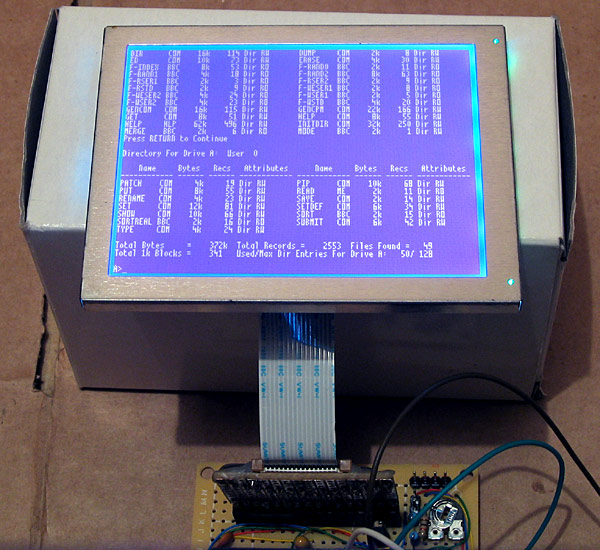
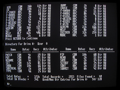
A handful of these VDU commands have been implemented, which is sufficient to run simple CP/M software. The generic CP/M version of BBC BASIC does not, naturally, support any hardware-specific features and as such lacks advanced text or drawing support (one can send commands directly to the output stream with the VDU statement but this isn't very user-friendly). I will need to work on this now that the hardware is coming together! The current VDC code can be downloaded here if you are interested in the changes that have been made.
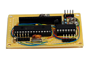
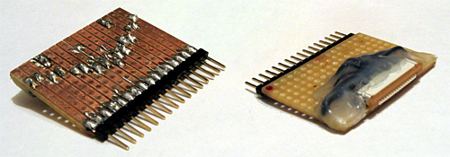
The above photo shows the newly constructed VDC hardware. All of my previous projects have been assembled on stripboard; as the projects have become more complex or simply smaller I've found stripboard to be increasingly awkward to work with. ICs can only really be orientated in one direction, and to reduce the size of circuits I've had to start cutting the tracks between holes (rather than the usual method which is to drill out an entire hole). The supplier I normally acquire parts from, Bitsbox, recently added three different sizes of perfboard to their catalogue so I thought I'd give it a go. I've found it much more pleasant to work with than stripboard, though not as easy to correct if you make a mistake and need to desolder a connection. You can certainly perform some interesting space-saving tricks on the underside of the board!
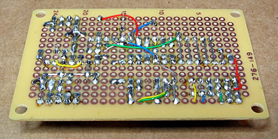
The Kynar insulation on the wire I switched to using also has the advantage of not melting when heated with a soldering iron, as I've had problems in previous projects where tightly-spaced wires will end up getting shorted together as the insulation between them melts.
I have mentioned that one pin header is used to connect the VDC to the computer. There are three others on the board; the two-pin one is for the composite video output, the six-pin one is for connection to a PICkit to reprogram the dsPIC and the four-pin one for the VGA output.
Now that I have moved the VDC onto a permanent circuit board I feel that I can start moving the rest of the computer in the same direction. The software is far from complete and the hardware is pretty rudimentary but it does basically work and having a more robust system to work on should make life a bit easier.
VGA output for the dsPIC33 VDC
Sunday, 25th July 2010
I have spent quite a while working on different projects that generate PAL video signals in software. This may seem a bit odd if you consider the fact that I don't own a TV, so tend to rely on a video capture card or VGA box to see the output of these projects on a computer monitor — something I do have a fair number of.
This reliance on another piece of technology between my project and the display device is not something I'm too keen on, so have spent some time adding native 640×480 60Hz VGA output to my dsPIC33 video display controller.
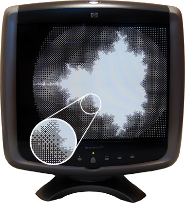
Another advantage of using a VGA monitor directly is that individual pixels are shown very crisply, unlike my video capture card or VGA box which tend to blur the image horizontally. This is shown in the zoomed in part of the above photo.
Generating a video signal for a VGA monitor is easier than generating a composite video signal for a PAL TV, as there are distinct pins for the image data, horizontal sync and vertical sync. One problem I did have, however, is with the length of the vertical sync pulse. I started with a very brief pulse (the same duration as the horizontal sync pulse) which worked fine with my old analogue CRT monitors but didn't work at all with my modern LCD monitor. The documentation I was using for timing information indicated that there were "two scanlines" for vertical sync so I extended the pulse to last for those two frames, which worked on the LCD but didn't on the CRTs. My final compromise has been to assert the vertical sync pin for the duration of a single scanline, which seems to work on all of my monitors.
When connected to a TV two microcontroller pins are used to drive a single load (composite input). When connected to a VGA monitor, however, a single microcontroller pin is used to drive three loads (red, green and blue inputs). I thought it prudent to check the datasheet for the dsPIC before connecting this increased load to the output pin where I was surprised to discover that the maximum source or sink current for each output pin is a measly 4mA — not even enough to drive an LED! I have added a buffer to each video output pin to protect the dsPIC — any buffer capable of sourcing up to 30mA or so should be sufficient (I'm using a 74F125, which can be seen in the bottom right of the above photo). I had previously been occasionally using the video output pins as inputs to check if there is a load on the output or not (such a load would indicate whether a TV or VGA monitor is plugged in or not) but I can no longer do this with the external buffer IC so have had to revise the circuit somewhat. Updated source code featuring the new VGA output code and an accompanying schematic are available for those who are interested!
Text and filled shapes for the dsPIC33 VDC
Thursday, 22nd July 2010
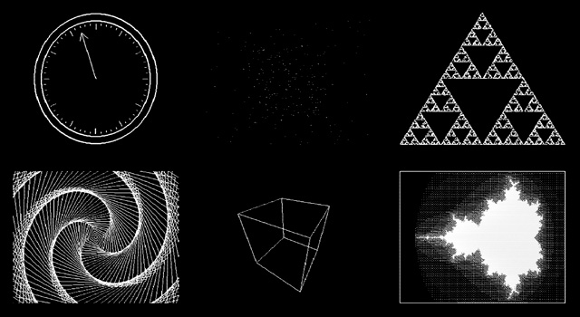
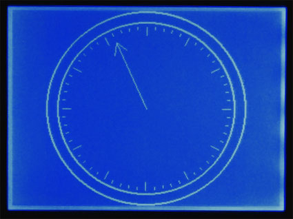
The dsPIC33 video display controller project I am working on needs to support several common text output and drawing operations offered by existing BBC BASIC implementations. The previous demo included basic point, line and circle outlining functions, but I also need to output text and outline (or fill) rectangles, circles, ellipses and triangles. On top of that the drawing operations need to support multiple colours and plotting modes. Owing to processing power and memory limitations the output is black and white only but different "shades" can be implemented with dither patterns. The plotting modes allow you to perform logical operations between what you are drawing and what's currently on the buffer — for example, you could fill a circle that is logically ORed with the existing background or draw a line that inverts every pixel along its length rather than applying the new colour.
Filled rectangles and text output produce the above image.
Finding suitable algorithms for some of these routines has been a little tricky at times. Due to the way that filled shapes can be set to invert (rather than overwrite) what's on the background there has to be zero overdraw and the outline of filled triangles should exactly match the outline of a triangle drawn by plotting a line between its three vertices; this makes combining triangles to form more complex shapes possible, as you can guarantee that the overlap between the two shared vertices of a pair of triangles covers the same pixels as a line drawn between those two vertices.
Filled triangles produce a solid cube.
I ended up writing a program in C# that would plot a random triangle using the triangle filler I was attempting to write and then compare its outline to that of a triangle drawn by plotting lines between the three vertices. The final code is chock full of special cases and workarounds but has been tested against hundreds of thousands of random triangles and seems to be working!
Due to a shortage of memory there is only a single frame buffer, which (naturally) means there is no double-buffering and hence smooth animation becomes a little tricky. When connected to a TV one can take advantage of the vertical blanking period to update the buffer (this is a period below and above the active display where you only need to feed sync signals, not image data, to the TV) and still get decent effects as long as you don't try to do too much. The LCD has no such vertical blanking period and so some of the demos look rather flickery.
I have captured a video of the output of the circuit when running the demo which can be seen above. The horizontal grey lines are a limitation of my video capture card; these lines appear correctly as alternating black and white pixels on a real TV set! You can download the code for this demo from my site along with a PDF of the schematic. As this is a work in progress I'm sure there are plenty of bugs left to squash but I think it's getting there, slowly but surely!
dsPIC33 VDC with GLCD or PAL TV output
Sunday, 4th July 2010
I have currently been using some terminal emulation software on my PC to see the output of the Z80 computer. It seems a little silly to rely on a large multi-gigahertz, multi-megabyte machine just to display the output from a machine at the megahertz and kilobyte end of the scale. I had previously done some work with a dsPIC33 to drive a 320×240 pixel graphical LCD so dug out its breadboard and dusted off the code to try to make something of it.
Inspired by John Burton's recent experiments with PAL TV output I decided that the first thing I should do is add support for TV output. The graphical LCD is nice but a little small and responds to pixel changes rather slowly, making animation very blurry.
I think the results are reasonably good. A lot of the code is shared with the old LCD driving code, which means that the LCD demos work fine with the TV too. Fortunately, retracing the TV is a much less CPU-intensive job than retracing the LCD. The PIC has an SPI peripheral that allows you to clock out eight or sixteen bits a bit at a time at a selected speed by writing to a single register, which is great for clocking out the pixel data on each scanline. Even better are the PIC's DMA channels, which allow you to output a selected number of bytes or words to a selected peripheral from a specified location in RAM with no CPU involvement; all I need to do on each line is to copy a complete scanline to the DMA memory, initiate a transfer from this memory to the SPI peripheral and the job is as good as done. Using the DMA hardware as opposed to writing to the SPI registers directly reduced the rendering time of the Mandelbrot fractal part of the demo from 33 seconds to 18 seconds.
One problem I haven't been able to resolve is that the PIC inserts a small delay between every DMA/SPI transfer, which results in every sixteenth pixel being a bit wider than the fifteen before it. This is especially noticed on dithered regions. If I write to the SPI registers directly this delay vanishes. I'm not sure if the picture quality increase is worth the loss of performance, so I'd rather find a proper fix for this! For the time being, here's a video of the demo as it currently runs:
The TV contains a 75Ω resistor to ground on its composite video input. Two resistors are used on two PIC pins to form a voltage divider to produce the required output voltages (0V for sync, 0.3V for black and 1V for white). When the TV is disconnected the output of the circuit is 3.3V (the supply voltage, equivalent to a logic "high") as there's no load resistance to pull it to the correct 0.3V (a logic "low"). This can be used to periodically check whether a TV is connected and to switch between the LCD and TV output modes.
The above is rather vague, and I would recommend Rickard Gunée's article entitled How to generate video signals in software using PIC for more detailed information! The code for the demo can be downloaded from my website for those who are interested.
Update: I've updated my code to use the SPI peripheral in slave mode and use a timer and output compare unit to generate the clock signal. This regular clock signal produces pixels of identical sizes the new code can be downloaded here.
Controlling a PG320240H-P9 with a dsPIC33FJ128GP802
Sunday, 21st March 2010
In a previous entry I mentioned that I had purchased a PG320240H-P9 graphical LCD. This is a 320×240 white-on-blue pixel display, and it does not have an on-board controller or RAM. To display something on it you need to constantly refresh it with picture data; in this instance, sending four pixels at a time, starting from the top left and working from left to right, top to bottom — a bit like the scanning pattern of a CRT monitor.
Connecting a circuit to the LCD is made slightly more tricky by its use of a 16-pin 1mm flexible flat cable. To get around this I soldered together an adaptor using a suitable FCC connector, pin strip, piece of stripboard and a fairly excessive quantity of hot melt adhesive. Even more tricky was the lack of a suitable datasheet for the LCD. After some digging I located this one for the PG320240WRM-HNNIS1 — it's slightly different, but contains timing diagrams and specifications that seem to work with the LCD I bought. One thing I still haven't worked out is the contrast adjustment; a 5K variable resistor between 0V and the relevant pin seems to have had the best results thus far. A helpful webpage, Graphical LCD controller for ST8024+ST8016 based displays, has a plain English description of how to drive the LCD, though as far as I'm aware the M pin should have its logic level toggled every frame, giving you a "glass" frequency of half of the refresh rate, not 200Hz-400Hz. The lack of a proper datasheet makes these things a little complicated!
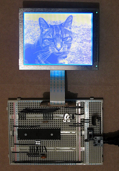
My first attempt to drive the LCD involved an ATmega644P, a microcontroller with 64KB of flash ROM and 4KB of RAM. The above photo shows it displaying a picture of a cat, which was stored in ROM and output using the following code:
#include <stdint.h>
#include <avr/io.h>
#include <avr/pgmspace.h>

#define LCD_FLM   (6)
#define LCD_M     (5)
#define LCD_C1    (4)
#define LCD_C2    (3)
#define LCD_D_OFF (2)

#define LCD_CONTROL_PORT (PORTC)
#define LCD_CONTROL_PIN  (PINC)
#define LCD_CONTROL_DDR  (DDRC)

#define LCD_DATA_PORT    (PORTA)
#define LCD_DATA_PIN     (PINA)
#define LCD_DATA_DDR     (DDRA)

#include "cat.h"

int main(void) {

    // Make control pins outputs.
    LCD_CONTROL_DDR |= _BV(LCD_FLM) | _BV(LCD_M) | _BV(LCD_C1) | _BV(LCD_C2) | _BV(LCD_D_OFF);

    // Make data pins outputs.
    LCD_DATA_DDR |= 0b1111;

    // Enable the LCD.
    LCD_CONTROL_PORT |= _BV(LCD_D_OFF);

    for(;;) {

        // Toggle the M pin to provide the LCD AC voltage.
        LCD_CONTROL_PIN |= _BV(LCD_M);

        const uint8_t* picture_ptr = cat_picture;

        // Scan 240 rows in the image.
        for (uint8_t row = 0; row < 240; ++row) {

            // Begin the line.
            LCD_CONTROL_PIN |= _BV(LCD_C1);
            LCD_CONTROL_PIN |= _BV(LCD_C1);

            if (row < 2) LCD_CONTROL_PIN |= _BV(LCD_FLM);

            // Send 40 eight-bit words.
            for (uint8_t column = 0; column < 40; ++column) {
                LCD_DATA_PORT = pgm_read_byte(picture_ptr) >> 4;
                LCD_CONTROL_PIN |= _BV(LCD_C2);
                LCD_CONTROL_PIN |= _BV(LCD_C2);
                LCD_DATA_PORT = pgm_read_byte(picture_ptr);
                LCD_CONTROL_PIN |= _BV(LCD_C2);
                LCD_CONTROL_PIN |= _BV(LCD_C2);
                ++picture_ptr;
            }
        }
    }

}
A 320×240 display has 76,800 pixels, and if you store each pixel as a single bit (so eight pixels per byte) you need 9600 bytes to store a complete frame, which clearly won't fit in the 4KB offered by the ATmega644P. Rather than upgrade to an AVR with more memory, I jumped to the dsPIC33FJ128GP802, a 16-bit microcontroller with 16KB of RAM. As well as quadrupling the RAM from the ATmega644P it also doubles the program memory (128KB from 64KB) and speed (40 MIPS from 20 MIPS). When working with AVRs I'd been using a slow home-made serial programmer, and rather than continue with this sorry state of affairs (lack of debugging capabilities is never fun, especially when it takes over a minute to program the microcontroller) I treated myself to a PICkit 3 Debug Express.
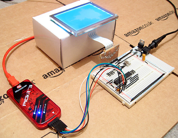
The above photo shows the LCD connected to the microcontroller as well as the PICkit 3. The dsPIC33FJ128GP802 requires a voltage supply from 3.0V to 3.6V, not the 5V I am used to, so to power it I have put two IN4001 rectifier diodes in series with the 5V regulator output. Each diode incurs a voltage drop of 0.7V, producing 3.6V for the rest of the circuit. The LCD is powered from the main 5V supply, but it seems happy with the 3.6V logic "high" from the dsPIC.
The LCD is connected to the dsPIC as follows:
- FLM to RB15
- M to RB14
- C1 to RB13
- C2 to RB12
- /D_OFF to RB11
- D0~D3 to RA0~RA3
A 10K resistor is included between /D_OFF and ground. This is very important, as it holds the /D_OFF line low when RB11 is floating (e.g. during reset), forcing the display off — if the display is powered, but is not being actively refreshed, the LCD panel can become overloaded and damaged.
I have knocked together a simple demo that shows a few different graphics on the LCD. The LCD is constantly refreshed by an interrupt service routine that runs in the background, leaving some CPU time to the user program. As there is only enough RAM for a single frame buffer, animation has to be quite simple to avoid flickering, but I've still managed to include my favourite spinning cube.
The project can be downloaded here. I'm still getting to grips with the dsPIC series; the code is likely to be pretty awful, and I still have a problem where the dsPIC resets itself every couple of minutes (I'm not really sure if this is a software or hardware issue). Still, it's a start, and I hope that I can use this LCD as the display for my Z80 computer project.
Update: Having seen this post, the chap who originally suggested that I investigate the dsPIC33FJ128GP802 sent me an email with some advice, chiefly about my poor power supply, missing decoupling capacitors and use of an electrolytic capacitor on the VCAP pin. I have since replaced the two rectifier diode affair with a proper 3.3V regulator for the power supply, added a decoupling capacitor across AVDD/AVSS and moved the decoupling capacitor between VDD/VSS closer to the microcontroller. I have also ordered some tantalum capacitors to replace the electrolytic one. A bit of debugging found that the watchdog timer is responsible for the spurious resets; I have disabled it in the code for the time being, which has stopped the resets.
Subscribe to an RSS feed that only contains items with the dsPIC33 VDC tag.