TV Demonstrator
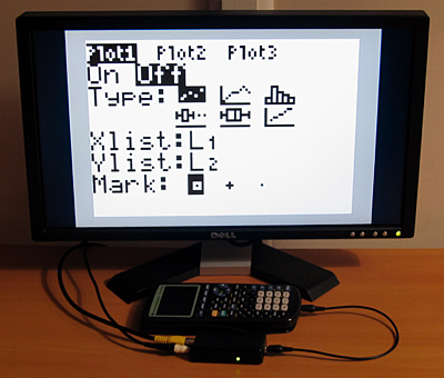
This easy-to-build electronic device allows you to take a screenshot of your calculator display and show it on an NTSC or PAL television set.

Unlike the TI-Presenter™ this does not require a special calculator or a USB adaptor; it uses the 2.5mm link port. The chief disadvantage of this method is that it does not automatically mirror what is shown on the calculator's display on the television; you need to press a button to manually capture the calculator's display.
The TV Demonstrator will only work in situations where the calculator allows you to capture a screenshot via the link port. It will therefore work in most places within the calculator's operating system, but will not work when the calculator is busy or otherwise not responding to screenshot requests. If in doubt, try using the screenshot function within your calculator linking software of choice to determine when it will work and when it won't.
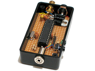
Click and drag on the above image to see a 360° view of the insides of the TV Demonstrator.
Supported calculators
The TV Demonstrator can be used with the TI-82, TI-83 and TI-83+. It should work with the TI-84+ and may work with the TI-73, but I have not been able to test these calculators.
To configure the device you will need to use a TI-83+ or TI-84+.
Due to the limited RAM on the microcontroller the TV Demonstrator will not support calculators with a resolution higher than 96×64 pixels.
Parts list
- An ATmega168 microcontroller.
- A 20MHz crystal.
- Two load capacitors for the crystal (12-22pF).
- An activity LED.
- A current-limiting resistor for the LED (1K5).
- A normally-open push button to act as a trigger.
- Two resistors to form the output DAC (ideally 450Ω and 900Ω, but 470Ω and 1K work in practice).
- Two capacitors for power supply smoothing (0.1µF and 10µF).
- An RCA ("phono") connector for the video output.
- A 2.5mm stereo jack socket for connection to the calculator.
You will also need a regulated +5V power supply. An LM7805 would work well in conjuction with an external power-supply unit or a 9V battery, or you could use a computer's USB port.
Schematic
Please consult the ATmega168 datasheet for more information. The following schematic does not include the 5V power supply.

The resistor values given for the DAC (450Ω/900Ω) are ideal, but the values in parentheses (470Ω/1K) work well in practice and are much easier to get hold of.
Firmware
The firmware, documentation and schematic for the project can be downloaded in a zip archive.
Precompiled firmware is available in the file TVDemonstrator.hex. You will need to send this to the ATmega168. You will also need to configure the ATmega168's fuses to use an external crystal oscillator and to not divide the clock by 8.
Suitable avrdude command-line arguments are as follows:
avrdude -p atmega168 -U flash:w:TVDemonstrator.hex:i
avrdude -p atmega168 -U lfuse:w:0xff:m -U hfuse:w:0xdf:m -U efuse:w:0x01:m
Alternatively, the Makefile can be used if you have AVR development tools installed:
make flash
make fuses
Usage
Connect the TV Demonstrator to the television and its power supply, then switch it on. A picture should be displayed on the television.
Now connect the calculator to the TV Demonstrator and press the trigger button. The device should take a screenshot of the calculator display and show it on the TV screen. The activity LED will be illuminated during the data transfer.
Configuration
The device can be configured using a TI-83+ or TI-84+. Configuration is performed by sending real variables to the calculator either via the LINK menu or the Send() command.
| Variable | Function |
|---|---|
| M | Sets the video mode (60 for NTSC, 50 for PAL). |
| X | Sets the display X offset (larger values move the display right). |
| Y | Sets the display Y offset (larger values move the display down). |
As an example, the following will set the device into the PAL mode when typed into the calculator's home screen:
50→M:Send(M
You can retrieve the current configuration using Get() or GetCalc(). For example, the following will nudge the display right every time you press ENTER once typed into the home screen:
Get(X:X+1→X:Send(X
The configuration is automatically saved. The NTSC and PAL modes have their own set of X and Y variables.
To reset the device to the original configuration, disconnect power to the device, hold the trigger button and then reconnect power. If you hold the trigger button for a couple of seconds the configuration should be reset.

