Quake 2 and Emulation
Wednesday, 1st August 2007
The current design of the Quake project is that there are a bunch of classes in the Data namespace that are used to decode Quake's structures in a fairly brain-dead manner. To do anything useful with it you need to build up your own structures suitable for the way you intend on rendering the level.
The problem comes in when you try to load resources from different versions of Quake. Quake 1 and Quake 2 have quite a few differences. One major one is that every BSP level in Quake contains its own mip textures. You can call a method in the BSP class which returns sane texture coordinates as it can inspect the texture dimensions inside itself. Quake 2 stores all of the textures externally in .wal resources - the BSP class can no longer calculate texture coordinates as it can't work out how large the textures are as it can't see outside itself.
I guess the only sane way to work this out is to hide the native types from the end user and wrap everything up, but I've never liked this much as you might neglect to wrap up something that someone else would find very important, or you do something that is unsuitable for the way they really wanted to work.
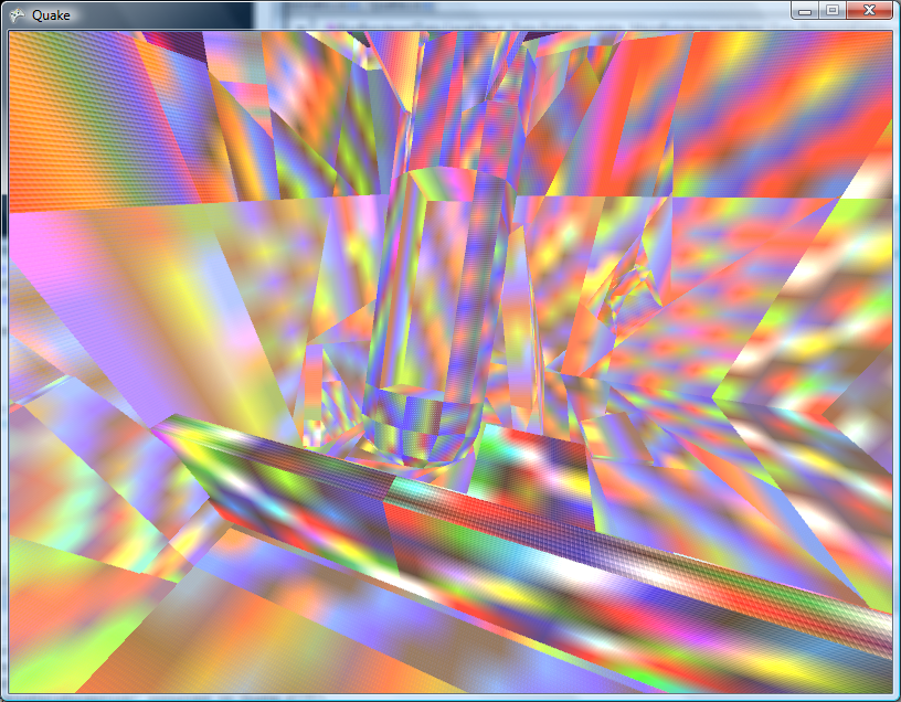
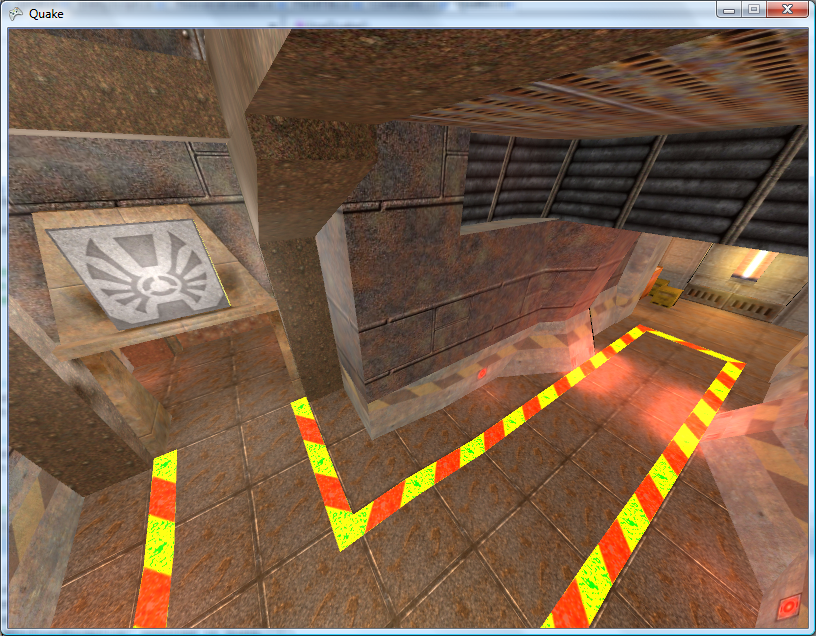
Anyhow. I've hacked around the BSP loader to within an inch of its life and it seems to be (sort of) loading Quake 2 levels for brute-force rendering. Quake 2 boasts truecolour lightmaps, improving the image quality quite significantly!
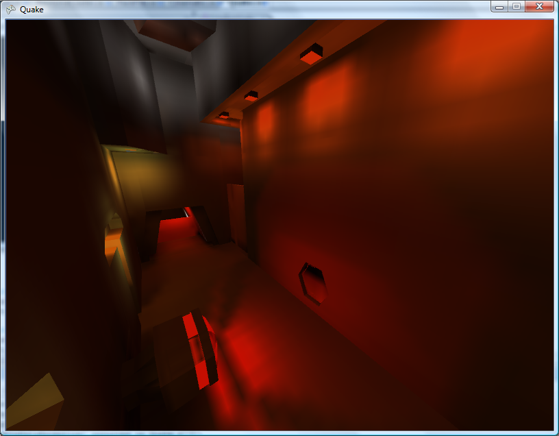
The truecolour lightmaps show off the Strogg disco lighting to its best effect. One of the problems with the Quake II BSP file format is that the indexing of lumps inside the file has changed. Not good.

That's a bit better.  Quake II's lightmaps tend to stick to the red/brown/yellow end of the spectrum, but that is a truecolour set of lightmaps in action!
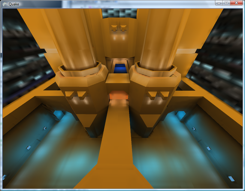
The lightmaps tend to look a bit grubby where they don't line up between faces. Some trick to join all lightmaps for a plane together into a single texture should do the trick, and reduce the overhead of having to load thousands of tiny textures (which I'm guessing have to be scaled up to a power-of-two). I'll have to look into it.
On to .wal (wall texture) loading - and I can't find a palette anywhere inside the Quake II pack files. I did find a .act (Photoshop palette) that claimed to be for Quake II, but it doesn't quite seem to match. It's probably made up of the right colours, but not in the right order.
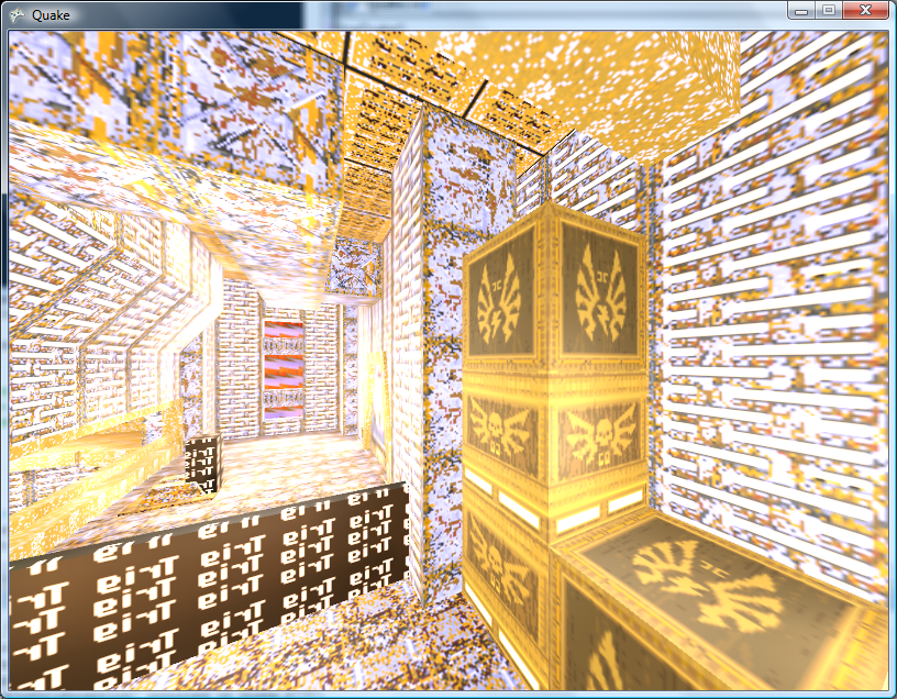
Fortunately I have some PAK files with replacement JPEG textures inside them and can load those instead for the moment.

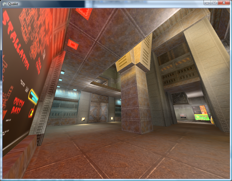
The brightness looks strange due to the bad way I apply the lightmaps - some kludgy forced two-pass affair with alpha blending modes set to something that sort of adds the two textures together in a not-very-convincing manner.
Can anyone recommend a good introduction to shaders for XNA? I'm not really trying to do anything that exciting.
This is a really bad and vague overview of the emulation technique I use in Cogwheel, so I apologise in advance. Emulation itself is very simple when done in the following manner - all you really need is a half-decent knowledge of how the computer you're emulating works at the assembly level. The following is rather Z80-specific.
At the heart of the system is its CPU. This device reads instructions from memory and depending on the value it reads it performs a variety of different actions. It has a small amount of memory inside itself which it uses to store its registers, variables used during execution. For example, the PC register is used as a pointer to the next instruction to fetch and execute from memory, and the SP register points at the top of the stack.
It can interact with the rest of the system in three main ways:
- Read/Write Memory
- Input/Output Hardware
- Interrupt Request
I assume you're familiar with memory. The hardware I refer to are peripheral devices such as video display processors, keypads, sound generators and so on. Data is written to and read from these devices on request. What the hardware device does with that data is up to it. I'll ignore interrupt requests for the moment.
The CPU at an electronic level communicates with memory and hardware using two buses and a handful of control pins. The two buses are the address bus and data bus. The address bus is read-only (when viewed from outside the CPU) and is used to specify a memory address or a hardware port number. It is 16 bits wide, meaning that 64KB memory can be addressed. Due to the design, only the lower 8-bits are normally used for hardware addressing, giving you up to 256 different hardware devices.
The data bus is 8-bits wide (making the Z80 an "8-bit" CPU). It can be read from or written to, depending on the current instruction.
The exact function of these buses - whether you're addressing memory or a hardware device, or whether you're reading or writing - is relayed to the external hardware via some control pins on the CPU itself. The emulator author doesn't really need to emulate these. Rather, we can do something like this:
class CpuEmulator {

	public virtual void WriteMemory(ushort address, byte value) {
		// Write to memory.
	}

	public virtual byte ReadMemory(ushort address) {
		// Read from memory.
		return 0x00;
	}

	public virtual void WriteHardware(ushort address, byte value) {
		// Write to hardware.
	}

	public virtual byte ReadHardware(ushort address) {
		// Read from hardware.
		return 0x00;
	}

}
A computer with a fixed 64KB RAM, keyboard on hardware port 0 and console (for text output) on port 1 might look like this:
class SomeBadComputer : CpuEmulator {

	private byte[] AllMemory = new byte[64 * 1024];

	public override void WriteMemory(ushort address, byte value) {
		AllMemory[address] = value;
	}

	public override byte ReadMemory(ushort address) {
		return AllMemory[address];
	}

	public override void WriteHardware(ushort address, byte value) {
		switch (address & 0xFF) {
			case 1:
				Console.Write((char)value);
				break;
		}
	}

	public override byte ReadHardware(ushort address) {
		switch (address & 0xFF) {
			case 0:
				return (byte)Console.ReadKey();
			default:
				return 0x00;
		}
	}

}
This is all very well, but how does the CPU actually do anything worthwhile?
It needs to read instructions from memory, decode them, and act on them. Suppose our CPU had two registers - 16-bit PC (program counter) and 8-bit A (accumulator) and this instruction set:
00nn   : Load 'nn' into accumulator.
01nn   : Output accumulator to port N.
02nn   : Input to accumulator from port N.
03nnnn : Read from memory address nnnn to accumulator.
04nnnn : Write accumulator to memory address nnnn.
05nnnn : Jump to address nnnn.
Extending the above CpuEmulator class, we could get something like this:
partial class CpuEmulator {

	public ushort RegPC = 0;
	public byte RegA = 0;

	private int CyclesPending = 0;

	public void FetchExecute() {
		switch (ReadMemory(RegPC++)) {
			case 0x00:
				RegA = ReadMemory(RegPC++);
				CyclesPending += 8;
				break;
			case 0x01:
				WriteHardware(ReadMemory(RegPC++), RegA);
				CyclesPending += 8;
				break;
			case 0x02:
				RegA = ReadHardware(ReadMemory(RegPC++));
				CyclesPending += 16;
				break;
			case 0x03:
				RegA = ReadMemory((ushort)(ReadMemory(RegPC++) + ReadMemory(RegPC++) * 256));
				CyclesPending += 16;
				break;
			case 0x04:
				WriteMemory((ushort)(ReadMemory(RegPC++) + ReadMemory(RegPC++) * 256), RegA);
				CyclesPending += 24;
				break;
			case 0x05:
				RegPC = (ushort)(ReadMemory(RegPC++) + ReadMemory(RegPC++) * 256);
				CyclesPending += 24;
				break;
			default:
				// NOP
				CyclesPending += 4;
				break;
		}
	}

}
The CyclesPending variable is used for timing. Instructions take a variable length of time to run (depending on complexity, length of opcode, whether it needs to access memory and so on). This time is typically measured in the number of clock cycles taken for the CPU to execute the instruction.
Using the above CyclesPending += x style one can write a function that will execute a particular number of cycles:
partial class CpuEmulator {

	public void Tick(int cycles) {
		CyclesPending -= cycles;
		while (CyclesPending < 0) FetchExecute();
	}

}
For some truly terrifying code, an oldish version of Cogwheel's instruction decoding switch block. That code has been automatically generated from a text file, I didn't hand-type it all.
Um... that's pretty much all there is. The rest is reading datasheets! Your CPU would need to execute most (if not all) instructions correctly, updating its internal state (and registers) as the hardware would. The non-CPU hardware (video processor, sound processor, controllers and so on) would also need to conform to data reads and writes correctly.
As far as timing goes, various bits of hardware need to run at their own pace. One scanline (of the video processor) is a good value for the Master System. Cogwheel provides this method to run the emulator for a single frame:
public void RunFrame() {
	this.VDP.RunFramePending = false;
	while (!this.VDP.RunFramePending) {
		this.VDP.RasteriseLine();
		this.FetchExecute(228);
	}
}
In the Master System's case, one scanline is displayed every 228 clock cycles. Some programs update the VDP on every scanline (eg changing the background horizontal scroll offset to skew the image in a driving game).
The above is embarrassingly vague, so if anyone is interested enough to want clarification on anything I'd be happy to give it.