Cylinders and translucent surfaces
Tuesday, 29th April 2008
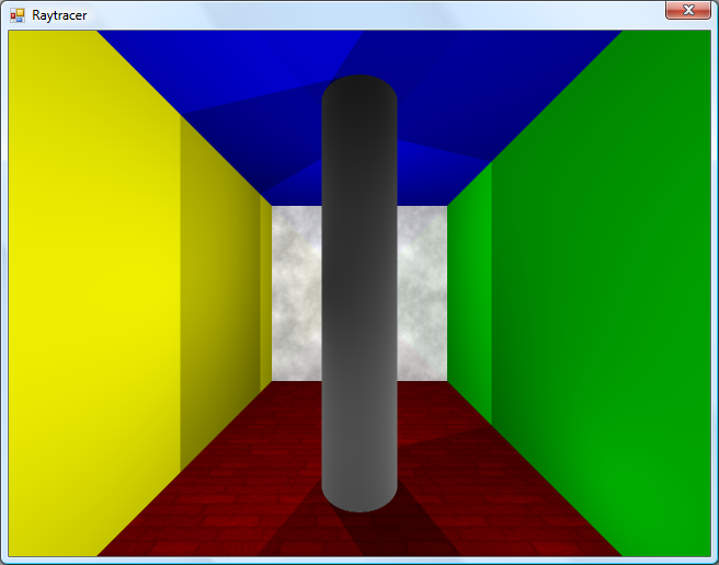
The first addition to the raytracer was a cylindrical surface, represented by two end points and a radius. In the two screenshots above, the cylinder is infinitely long - not very useful. However, by calculating the point on the cylinder's axis that is closest to the struck point on its surface you can work out how far along its axis you are, and from that whether you are between either of the cylinder's ends.
The cylinder can have its ends optionally capped. To add the caps, you can create plane that has a normal that points in the the direction of the cylinder's axis. If you collide with the plane, you can then calculate the distance between the point you struck on it and the end coordinate of the cylinder. If this distance is smaller than the radius of the cylinder, you've hit one of the end caps.
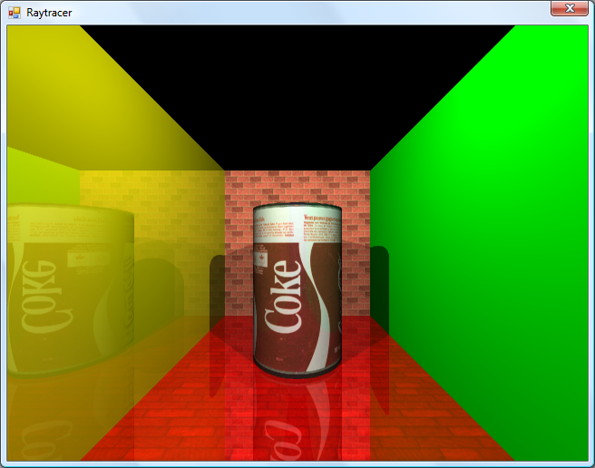
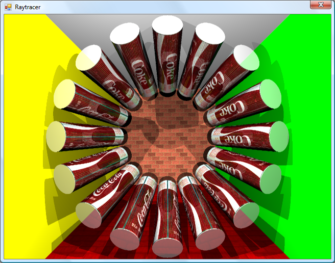
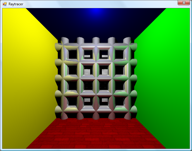
Texturing the cylinders proved rather difficult. The v component of the texture component can be calculated by working how far along the cylinder's axis you are - easy. However, to wrap a texture around the rotational axis of the cylinder is a bit more complicated. In the first screenshot, I simply used Math.Atan2(z,x) to get the angle, and hence texture coordinate - but this only works if the cylinder points along the y axis. If I had another vector that lay perpendicular to the cylinder's axis I could use the dot product to work out its angle, but I don't. The cross product could generate one, but I'd need another vector to cross the axis with... In the end, this post came to my rescue, and I managed to get it working for cylinders pointing along any axis - producing the second screenshot.
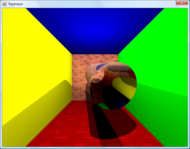
An addition I've wanted to make for a while was support for translucent surfaces.
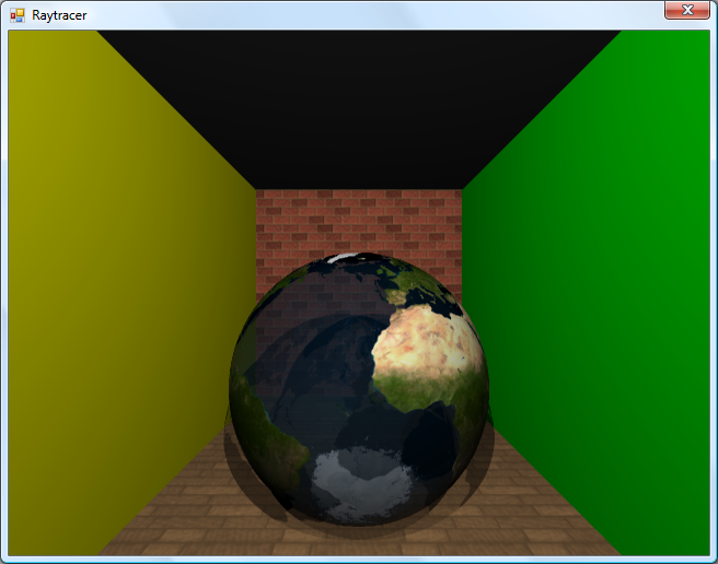
This required a few changes to the structure of the raytracer. Previously, all methods for calculating ray intersections had to return a single Collision object, which contained a boolean flag specifying whether the collision was succesful. A translucent sphere would need to return two collision points - one as the ray enters the front and one as it leaves the back of its surface. To this end, all collision detection methods now return an array (empty or null if no collisions were made), and each collision has a flag indicating whether the collision was made by the ray entering the solid or leaving the solid (this is required, for example, to invert surface normals for correct shading).
Once the nearest struck point to the camera has been handled (including recursive reflection-handling code) it is checked to see if it's on a translucent surface. If so, the raytracer continues raytracing away from the camera, and blends the new result with the existing result based on its opacity. By stopping and starting again, one can adjust the direction of the ray - for example, to add a refraction effect (which I have not yet got working  ).
).
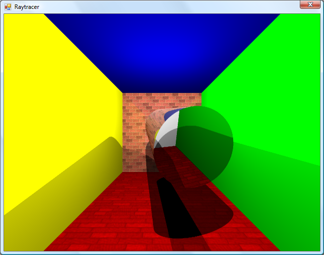
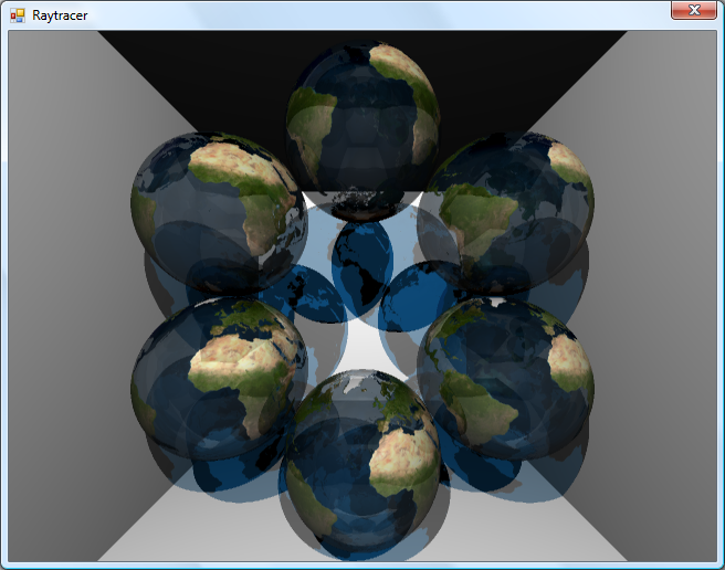
One trick the above image misses is that it's still simply scaling down the intensity of the light by the opacity of the surface it passes through. It would look nicer if the light was coloured by the surface it passes through; so, in the above example, the white light shining through the blue water on the sphere should cast blue-tinted shadows.
Whilst it's far from being real-time, I can still make it dump out a sequence of frames to create a basic animation.
