Building a VGA line blanker and 3D glasses driver
Monday, 15th February 2010
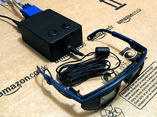
Assembling a circuit on breadboard is a good way to experiment with electronics, but the result is not something you could really use – it's bulky, fragile and awkward to set up. It's far nicer to solder the components of the circuit together to form a more permanent device and put it in a enclosure to make it robust. This is not something I'm especially good at, but something I thought I'd try with the VGA line blanker and LCD shutter glasses controller I've been experimenting with recently.
In the past I've struggled along with a hand drill and the nail file on a Swiss Army knife, but have more recently acquired a high-speed rotary tool and an assortment of attachments which make things much easier. I took some photos when building this project, which I've documented below; I'm not sure my techniques are very efficient, but I do get there in the end. I'd be very glad to hear any advice anyone has!
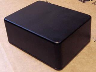
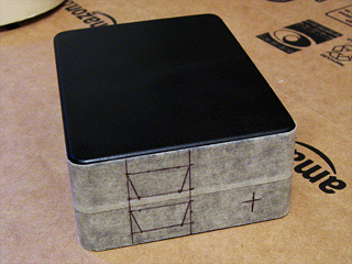
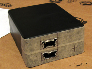
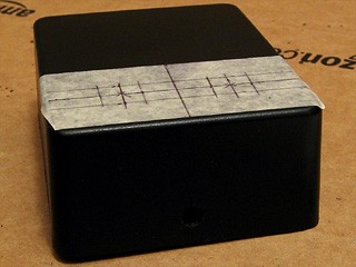
I started with a plain project box. Having planned roughly where I was going to put the VGA ports and DC power socket, I covered one side of the box in masking tape and drew on where I was going to put the holes.
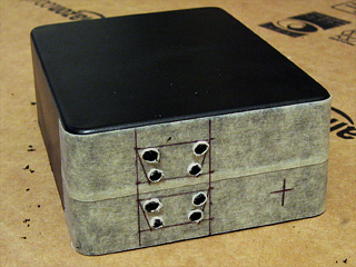
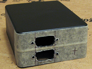
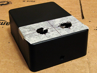
To cut straight-edged holes, such as those required for a D-subminiature connector, I drill a hole in each corner and use a small cylindrical burr to cut between the holes. This leaves a very rough edge, but is a good start.
I then widen the hole using a large cylindrical burr and a needle file until the part I'm attempting to mount fits snugly.
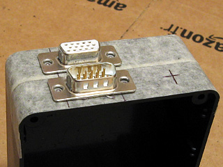
When I had both VGA connectors in place, I marked and drilled the holes for the jack posts that the VGA leads will screw into. Neither hole is especially neatly cut, but the D-subminiature connector overlaps the hole sufficiently to hide any shoddy workmanship.
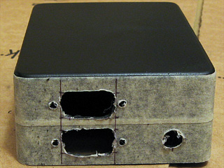
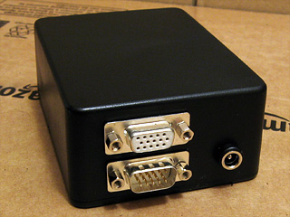
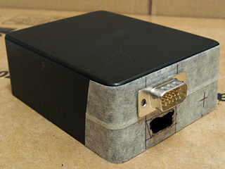
The last part of the back is the DC power socket. As I don't have a drill bit large enough to cut the hole on its own, I drill it as large as I can then widen it using the cylindrical burrs mentioned before. With all of the holes cut, I inserted the components to see how they look and identified one problem – I'd underestimated how fat the connectors on the end of VGA leads are. Fortunately, I have a slim VGA cable that fits, but a regular sized one does not – in future I'll need to remember to put the VGA connectors further apart!
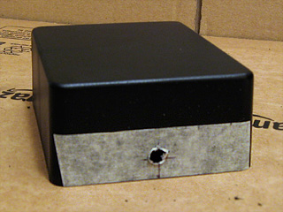
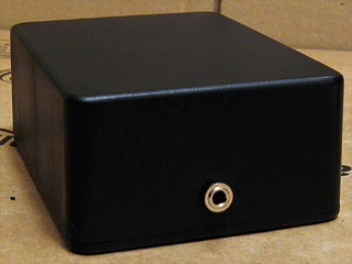
With that mistake fresh in my mind, I thought I'd move onto something a bit more difficult to get wrong – the 3.5mm stereo jack on the front of the box to plug the glasses into. This is just another round hole, cut in the same way as the DC power socket.
The two control switches on the top of the box require much larger holes. These were cut in the same way as before – a small hole is gradually widened by using a cylindrical burr. This is a very tedious job, not helped by having to keep stopping to clean the melted plastic that adheres to the burr.
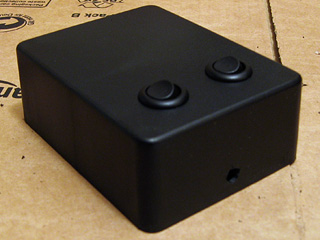
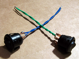
Finally, the switches were installed. I was originally going to use latching push buttons, but had previously used those nice round rocker switches as the power switch on the AVR TV Game project so opted to use them instead.
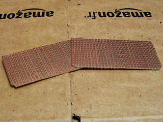
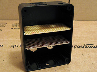
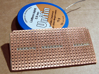
The final bit of physical work was to cut some stripboard down to size to fit inside the enclosure. These were cut by first scoring along the tracks where the cut was to be made, then snapping the board over the edge of a table. This results in a clean break, but to ensure a snug fit the boards were tidied up with a sanding drum. The lid (or, in my case, base) of the enclosure has a raised edge that fits inside the box, so the sanding drum was also used to remove two of the corners of the stripboard pieces to allow the base to fit.
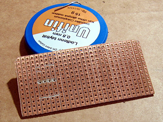
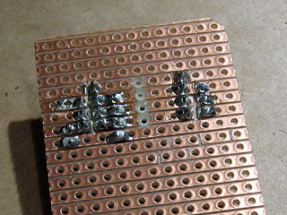
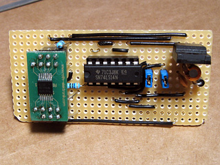
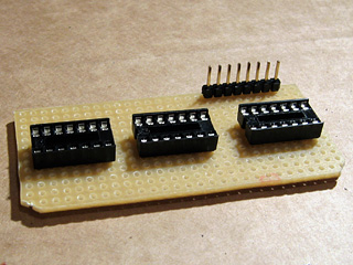
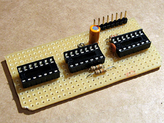
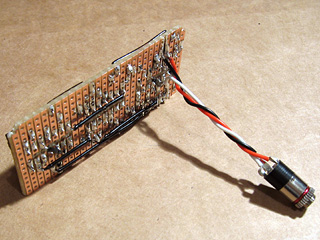
The next stage was to move onto the electronics, and I started with the circuit board that was to host the video amplifier IC, voltage regulator and Schmitt trigger on vsync/hsync. The video amplifier is attached to a TSSOP14 adaptor that has a D-shaped pin configuration, with two rows of four pins and two rows of three pins. Having cut through the tracks in the stripboard to mount the amplifier, I needed to find some suitable pin sockets.

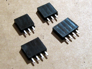
As I don't have any pin sockets with just three pins in them (only two, four and eight) I cut two eight-way pin sockets in two with a pair of wire cutters then tidied up the ragged edges with a sanding drum and needle file.
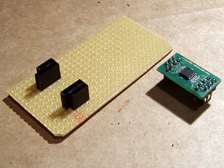
With the pin sockets soldered in place you can see the D shape I mentioned above. I don't generally plan stripboard circuits very thoroughly, preferring to start by placing large components in approximately the right location with respect to where the external connectors are and how they need to relate to other components. Once those are in place I add smaller components (such as discrete resistors or capacitors) before finishing by adding the wire links to connect all of the parts together. This does lead to situations where I wish that I'd placed a component one hole along to give myself more space or to avoid having to insert so many wire links, but it generally works.
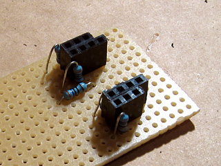
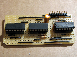
With the video amplifier in position, I added the resistors that are required on its inputs and outputs. To keep the circuit reasonably compact I cut through stripboard tracks between the holes using a conical HSS burr with a small tip – this is an especially useful tool when you need to deal with double-row pin sockets
I then added the support circuitry for the voltage regulator (smoothing capacitors and a rectifier diode to protect the circuit if the polarity of the power supply is incorrect) and a socket for the Schmitt trigger IC. I find the easiest way to keep components in place on any sort of through-hole board is to tape them down firmly with masking tape before soldering – bending the legs out makes the parts much harder to remove if you make a mistake. Blu-Tack is easier to use but has a habit of melting when soldering and leaving an unpleasant blue residue on your circuit, so I'd advise against it! To make this part of the circuit slightly more future-proof a pair of jumpers are used to connect the sync lines (vsync and hsync) from the VGA input and VGA output together. These could be removed if I decided to change the logic board to override these signals – for example, as part of a sync-doubler, which injects a vsync pulse half way down the screen.
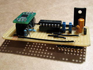
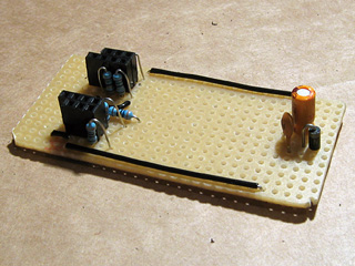
I finally added the bulkiest components; the 5V regulator and the pin header to connect the upper and lower boards together. Soldering pin headers to the underside of a board is a fiddly job, but is required in this instance to connect the bottom of the upper board to the top of the lower board.
With the upper board completed it was time to put it into the enclosure and solder the VGA connectors and DC power socket to it. This is the part I least enjoy.
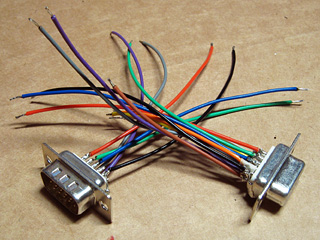
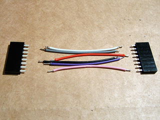
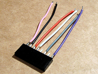
I started by soldering some stranded wire to the VGA connectors. Most of the wires are the same length, as they are required to carry signals to and from the circuit, but some wires are shorter and only connected to one of the VGA connectors. These are the white, yellow, orange and brown wires in the above photo, and these are attached to pins used to exchange information between the PC and the monitor (e.g. supported resolutions and refresh rates). As we're not interested in these, they're connected straight through from one connector to the other.
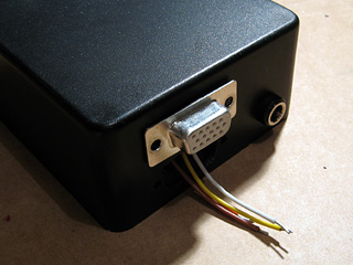
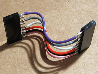
I inserted the VGA connector with these identification pins into the top hole, passed the shorter identification wires through the other and soldered them to the second VGA connector. This leaves the red, green, blue, vsync, hsync and ground pins loose inside, ready to be connected to the upper circuit board.
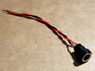
The DC power socket also needs to be connected to the circuit board, but at only two wires that's a much simpler job.
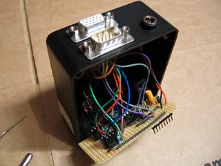
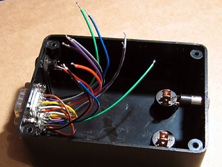
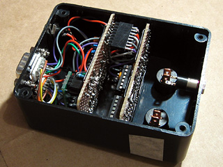
All of the loose leads are soldered onto the circuit board and stripboard is slotted into place inside the enclosure. The wires could be shorter, but that would have made soldering them a bit harder.
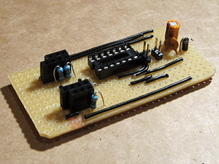
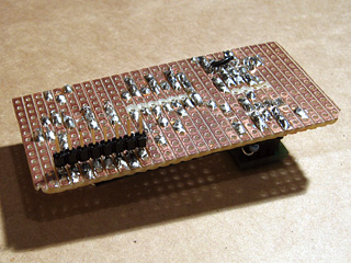
The lower circuit board will host the main logic for the project – it receives the vsync and hsync signals, and uses these to control whether the video signal should be blanked or not, and which shutter on the glasses should be closed and which should be open. It also contains the oscillator that generates the AC voltage that drives the glasses. I arranged the three logic ICs roughly next to eachother according to their layout on the breadboard version of the circuit and cut the stripboard tracks as appropriate.
I started by adding the sockets for the ICs and pin header to connect this circuit board to the video amplifier one, then added the discrete components. As before, I taped the components down before soldering them in place to make the task easier. Being able to copy the circuit directly from the breadboard version also made the task much easier.
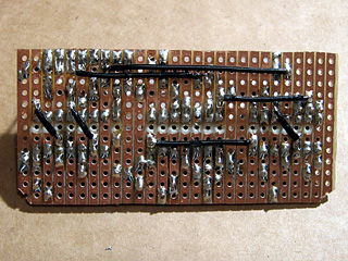
The last step for this part of the project was, as before, adding the wire links. Rather than run long wires around ICs I found it more practical to solder a few wires onto the underside of the stripboard.
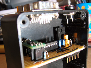
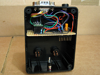
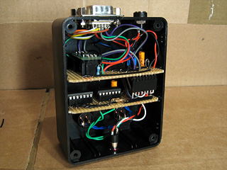
The two circuit boards needed to be connected together somehow. Without the facilities to make a proper ribbon cable, I just soldered some lengths of stranded wire (rather messily) between two pin sockets. As I'm not outputting anything to vsync or hsync (I'm feeding the input sync signals straight back to the output via the jumpers previously discussed), I didn't need to connect anything to these pins – hence the apparently missing wires in the photos.
The cable to connect the two boards together needed to be bent to fit – it's getting snug, but everything's in there without having to be forced, which is a good sign.
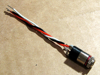
The next job was to attach the 3.5mm stereo jack that the LCD shutter glasses are plugged into. This is pushed through the hole in the enclosure from the inside and screwed on from the outside, so it can be soldered directly to the circuit board without having to thread it through the hole first. The small red "washer" is a length of enamelled wire that has been bent around the thread of the jack socket and is used as a spacer – without it, quite a lot of the thread protrudes from the front of the box, looking rather untidy.
Last of all are the two control switches. These are soldered to the track side of the stripboard like the stereo jack, but must be snapped through their holes in the enclosure first, which is why they were left until last. Everything is slotted into place, the base of the enclosure is screwed on, and the project is pretty much complete.
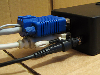
The VGA cables don't fit especially well – the D-subminiature sockets are a bit too close to eachother. If I use a thin VGA extension cable and wiggle the leads I can just about get both to screw in.
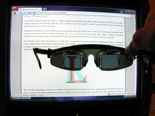
The demonstration pattern from some previous ramblings of mine is quite useful for testing 3D glasses, and by holding the left eye of the shutter glasses to the screen you can see that only the "L" part of the image is let through.