Thinking about CP/M
Wednesday, 24th February 2010
It's been some time since I worked on my Z80 computer project, but the recent electronics projects I've completed have got me thinking about it again.
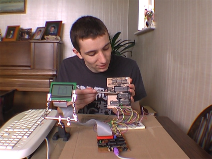
I did record a video to demonstrate the basic parts of the computer and some of its flaws a few months ago, which can be seen above. However, I'm now thinking of a more radical redesign than fixing the I/O board's shortcomings.
One of the reasons for my lack of motivation is that even if I did get something working I wouldn't have much software to run on it; it would be a lot of work to write software that only ran on that one particular machine. BBC BASIC helps somewhat, but an even better solution would be to model the device on an existing machine and run its operating system on it.
Fortunately, there was a popular operating system for the 8080 (and, by extension, the Z80) – CP/M. This is a very simple operating system that inspired DOS. Crucially, it is not hardware-specific, the source code is available and there is a wide range of software available for it, including BBC BASIC.
CP/M is made up of three main components. At the highest level is the Console Command Processor, or CCP. This provides the command-line interface, a handful of built-in commands and handles loading and executing external programs. It achieves this with the aid of the Basic Disk Operating System, or BDOS, which exposes a number of useful routines for a variety of tasks, such as outputting text to the display, searching for files on the disk or reading console input.
Both of the above components are machine-independent – they simply need to be copied to the correct address in RAM when the computer starts. Relocating them to a particular address requires setting a single value in their respective source files and reassembling them, which is nice and easy. It's the third component – the Basic I/O System, or BIOS – that requires a bit more work. This is the only part that is tailored to a particular machine's hardware, and my current implementation is listed below.
CCP    = $DC00
BDOS   = $E406
BIOS   = $F200

IOBYTE = $0003
CDISK  = $0004

DMAAD  = $0008
CTRACK = $000A
CSEC   = $000C

.org BIOS

	jp BOOT    ; COLD START
WBOOTE
	jp WBOOT   ; WARM START
	jp CONST   ; CONSOLE STATUS
	jp CONIN   ; CONSOLE CHARACTER IN
	jp CONOUT  ; CONSOLE CHARACTER OUT
	jp LIST    ; LIST CHARACTER OUT
	jp PUNCH   ; PUNCH CHARACTER OUT
	jp READER  ; READER CHARACTER OUT
	jp HOME    ; MOVE HEAD TO HOME POSITION
	jp SELDSK  ; SELECT DISK
	jp SETTRK  ; SET TRACK NUMBER
	jp SETSEC  ; SET SECTOR NUMBER
	jp SETDMA  ; SET DMA ADDRESS
	jp READ    ; READ DISK
	jp WRITE   ; WRITE DISK
	jp LISTST  ; RETURN LIST STATUS
	jp SECTRAN ; SECTOR TRANSLATE

DISKPARAM
	.dw $0000  ; No sector translation.
	.dw $0000  ; Scratch
	.dw $0000  ; Scratch
	.dw $0000  ; Scratch
	.dw DIRBUF ; Address of a 128-byte scratch pad area for directory operations within BDOS. All DPHs address the same scratch pad area.
	.dw DPBLK  ; Address of a disk parameter block for this drive. Drives with identical disk characteristics address the same disk parameter block.
	.dw CHK00  ; Address of a scratch pad area used for software check for changed disks. This address is different for each DPH.
	.dw ALL00  ; Address of a scratch pad area used by the BDOS to keep disk storage allocation information. This address is different for each DPH.

DIRBUF
	.fill 128

DPBLK           ; DISK PARAMETER BLOCK, COMMON TO ALL DISKS
	.DW 26      ; SECTORS PER TRACK
	.DB 3       ; BLOCK SHIFT FACTOR
	.DB 7       ; BLOCK MASK
	.DB 0       ; NULL MASK
	.DW 242     ; DISK SIZE-1
	.DW 63      ; DIRECTORY MAX
	.DB 192     ; ALLOC 0
	.DB 0       ; ALLOC 1
	.DW 16      ; CHECK SIZE
	.DW 2       ; TRACK OFFSET

CHK00
	.fill 16

ALL00
	.fill 31

; =========================================================================== ;
; BOOT                                                                        ;
; =========================================================================== ;
; The BOOT entry point gets control from the cold start loader and is         ;
; responsible for basic system initialization, including sending a sign-on    ;
; message, which can be omitted in the first version.                         ;
; If the IOBYTE function is implemented, it must be set at this point.        ;
; The various system parameters that are set by the WBOOT entry point must be ;
; initialized, and control is transferred to the CCP at 3400 + b for further  ;
; processing. Note that register C must be set to zero to select drive A.     ;
; =========================================================================== ;
BOOT
	xor a
	ld (IOBYTE),a
	ld (CDISK),a
	jp GOCPM

; =========================================================================== ;
; WBOOT                                                                       ;
; =========================================================================== ;
; The WBOOT entry point gets control when a warm start occurs.                ;
; A warm start is performed whenever a user program branches to location      ;
; 0000H, or when the CPU is reset from the front panel. The CP/M system must  ;
; be loaded from the first two tracks of drive A up to, but not including,    ;
; the BIOS, or CBIOS, if the user has completed the patch. System parameters  ;
; must be initialized as follows:                                             ;
;                                                                             ;
; location 0,1,2                                                              ;
;     Set to JMP WBOOT for warm starts (000H: JMP 4A03H + b)                  ;
;                                                                             ;
; location 3                                                                  ;
;     Set initial value of IOBYTE, if implemented in the CBIOS                ;
;                                                                             ;
; location 4                                                                  ;
;     High nibble = current user number, low nibble = current drive           ;
;                                                                             ;
; location 5,6,7                                                              ;
;     Set to JMP BDOS, which is the primary entry point to CP/M for transient ;
;     programs. (0005H: JMP 3C06H + b)                                        ;
;                                                                             ;
; Refer to Section 6.9 for complete details of page zero use. Upon completion ;
; of the initialization, the WBOOT program must branch to the CCP at 3400H+b  ;
; to restart the system.                                                      ;
; Upon entry to the CCP, register C is set to thedrive;to select after system ;
; initialization. The WBOOT routine should read location 4 in memory, verify  ;
; that is a legal drive, and pass it to the CCP in register C.                ;
; =========================================================================== ;
WBOOT

GOCPM
	ld a,$C3      ; C3 IS A JMP INSTRUCTION
	ld ($0000),a  ; FOR JMP TO WBOOT
	ld hl,WBOOTE  ; WBOOT ENTRY POINT
	ld ($0001),hl ; SET ADDRESS FIELD FOR JMP AT 0

	ld ($0005),a  ; FOR JMP TO BDOS
	ld hl,BDOS    ; BDOS ENTRY POINT
	ld ($0006),hl ; ADDRESS FIELD OF JUMP AT 5 TO BDOS

	ld bc,$0080   ; DEFAULT DMA ADDRESS IS 80H
	call SETDMA

	ei            ; ENABLE THE INTERRUPT SYSTEM
	ld a,(CDISK)  ; GET CURRENT DISK NUMBER
	ld c,a        ; SEND TO THE CCP
	jp CCP        ; GO TO CP/M FOR FURTHER PROCESSING

; =========================================================================== ;
; CONST                                                                       ;
; =========================================================================== ;
; You should sample the status of the currently assigned console device and   ;
; return 0FFH in register A if a character is ready to read and 00H in        ;
; register A if no console characters are ready.                              ;
; =========================================================================== ;
CONST
	out (2),a \ ret

; =========================================================================== ;
; CONIN                                                                       ;
; =========================================================================== ;
; The next console character is read into register A, and the parity bit is   ;
; set, high-order bit, to zero. If no console character is ready, wait until  ;
; a character is typed before returning.                                      ;
; =========================================================================== ;
CONIN
	out (3),a \ ret

; =========================================================================== ;
; CONOUT                                                                      ;
; =========================================================================== ;
; The character is sent from register C to the console output device.         ;
; The character is in ASCII, with high-order parity bit set to zero. You      ;
; might want to include a time-out on a line-feed or carriage return, if the  ;
; console device requires some time interval at the end of the line (such as  ;
; a TI Silent 700 terminal). You can filter out control characters that cause ;
; the console device to react in a strange way (CTRL-Z causes the Lear-       ;
; Siegler terminal to clear the screen, for example).                         ;
; =========================================================================== ;
CONOUT
	out (4),a \ ret

; =========================================================================== ;
; LIST                                                                        ;
; =========================================================================== ;
; The character is sent from register C to the currently assigned listing     ;
; device. The character is in ASCII with zero parity bit.                     ;
; =========================================================================== ;
LIST
	out (5),a \ ret

; =========================================================================== ;
; PUNCH                                                                       ;
; =========================================================================== ;
; The character is sent from register C to the currently assigned punch       ;
; device. The character is in ASCII with zero parity.                         ;
; =========================================================================== ;
PUNCH
	out (6),a \ ret

; =========================================================================== ;
; READER                                                                      ;
; =========================================================================== ;
; The next character is read from the currently assigned reader device into   ;
; register A with zero parity (high-order bit must be zero); an end-of-file   ;
; condition is reported by returning an ASCII CTRL-Z(1AH).                    ;
; =========================================================================== ;
READER
	out (7),a \ ret

; =========================================================================== ;
; HOME                                                                        ;
; =========================================================================== ;
; The disk head of the currently selected disk (initially disk A) is moved to ;
; the track 00 position. If the controller allows access to the track 0 flag  ;
; from the drive, the head is stepped until the track 0 flag is detected. If  ;
; the controller does not support this feature, the HOME call is translated   ;
; into a call to SETTRK with a parameter of 0.                                ;
; =========================================================================== ;
HOME
	ld bc,0
	jp SETTRK

; =========================================================================== ;
; SELDSK                                                                      ;
; =========================================================================== ;
; The disk drive given by register C is selected for further operations,      ;
; where register C contains 0 for drive A, 1 for drive B, and so on up to 15  ;
; for drive P (the standard CP/M distribution version supports four drives).  ;
; On each disk select, SELDSK must return in HL the base address of a 16-byte ;
; area, called the Disk Parameter Header, described in Section 6.10.          ;
; For standard floppy disk drives, the contents of the header and associated  ;
; tables do not change; thus, the program segment included in the sample      ;
; CBIOS performs this operation automatically.                                ;
;                                                                             ;
; If there is an attempt to select a nonexistent drive, SELDSK returns        ;
; HL = 0000H as an error indicator. Although SELDSK must return the header    ;
; address on each call, it is advisable to postpone the physical disk select  ;
; operation until an I/O function (seek, read, or write) is actually          ;
; performed, because disk selects often occur without ultimately performing   ;
; any disk I/O, and many controllers unload the head of the current disk      ;
; before selecting the new drive. This causes an excessive amount of noise    ;
; and disk wear. The least significant bit of register E is zero if this is   ;
; the first occurrence of the drive select since the last cold or warm start. ;
; =========================================================================== ;
SELDSK
	ld hl,DISKPARAM
	ld a,c
	or a
	ret z
	ld hl,$0000 ; Only disc 0 is supported.
	ret

; =========================================================================== ;
; SETTRK                                                                      ;
; =========================================================================== ;
; Register BC contains the track number for subsequent disk accesses on the   ;
; currently selected drive. The sector number in BC is the same as the number ;
; returned from the SECTRAN entry point. You can choose to seek the selected  ;
; track at this time or delay the seek until the next read or write actually  ;
; occurs. Register BC can take on values in the range 0-76 corresponding to   ;
; valid track numbers for standard floppy disk drives and 0-65535 for         ;
; nonstandard disk subsystems.                                                ;
; =========================================================================== ;
SETTRK
	ld (CTRACK),bc
	ret

; =========================================================================== ;
; SETSEC                                                                      ;
; =========================================================================== ;
; Register BC contains the sector number, 1 through 26, for subsequent disk   ;
; accesses on the currently selected drive. The sector number in BC is the    ;
; same as the number returned from the SECTRAN entry point. You can choose to ;
; send this information to the controller at this point or delay sector       ;
; selection until a read or write operation occurs.                           ;
; =========================================================================== ;
SETSEC
	ld (CSEC),bc
	ret

; =========================================================================== ;
; SETDMA                                                                      ;
; =========================================================================== ;
; Register BC contains the DMA (Disk Memory Access) address for subsequent    ;
; read or write operations. For example, if B = 00H and C = 80H when SETDMA   ;
; is called, all subsequent read operations read their data into 80H through  ;
; 0FFH and all subsequent write operations get their data from 80H through    ;
; 0FFH, until the next call to SETDMA occurs. The initial DMA address is      ;
; assumed to be 80H. The controller need not actually support Direct Memory   ;
; Access. If, for example, all data transfers are through I/O ports, the      ;
; CBIOS that is constructed uses the 128 byte area starting at the selected   ;
; DMA address for the memory buffer during the subsequent read or write       ;
; operations.                                                                 ;
; =========================================================================== ;
SETDMA
	ld (DMAAD),bc
	ret

; =========================================================================== ;
; READ                                                                        ;
; =========================================================================== ;
; Assuming the drive has been selected, the track has been set, and the DMA   ;
; address has been specified, the READ subroutine attempts to read one sector ;
; based upon these parameters and returns the following error codes in        ;
; register A:                                                                 ;
;                                                                             ;
;     0 - no errors occurred                                                  ;
;     1 - nonrecoverable error condition occurred                             ;
;                                                                             ;
; Currently, CP/M responds only to a zero or nonzero value as the return      ;
; code. That is, if the value in register A is 0, CP/M assumes that the disk  ;
; operation was completed properly. If an error occurs the CBIOS should       ;
; attempt at least 10 retries to see if the error is recoverable. When an     ;
; error is reported the BDOS prints the message BDOS ERR ON x: BAD SECTOR.    ;
; The operator then has the option of pressing a carriage return to ignore    ;
; the error, or CTRL-C to abort.                                              ;
; =========================================================================== ;
READ
	out (13),a \ ret

; =========================================================================== ;
; WRITE                                                                       ;
; =========================================================================== ;
; Data is written from the currently selected DMA address to the currently    ;
; selected drive, track, and sector. For floppy disks, the data should be     ;
; marked as nondeleted data to maintain compatibility with other CP/M         ;
; systems. The error codes given in the READ command are returned in register ;
; A, with error recovery attempts as described above.                         ;
; =========================================================================== ;
WRITE
	out (14),a \ ret

; =========================================================================== ;
; LISTST                                                                      ;
; =========================================================================== ;
; You return the ready status of the list device used by the DESPOOL program  ;
; to improve console response during its operation. The value 00 is returned  ;
; in A if the list device is not ready to accept a character and 0FFH if a    ;
; character can be sent to the printer. A 00 value should be returned if LIST ;
; status is not implemented.                                                  ;
; =========================================================================== ;
LISTST
	out (15),a \ ret

; =========================================================================== ;
; SECTRAN                                                                     ;
; =========================================================================== ;
; Logical-to-physical sector translation is performed to improve the overall  ;
; response of CP/M. Standard CP/M systems are shipped with a skew factor of   ;
; 6, where six physical sectors are skipped between each logical read         ;
; operation. This skew factor allows enough time between sectors for most     ;
; programs to load their buffers without missing the next sector. In          ;
; particular computer systems that use fast processors, memory, and disk      ;
; subsystems, the skew factor might be changed to improve overall response.   ;
; However, the user should maintain a single-density IBM-compatible version   ;
; of CP/M for information transfer into and out of the computer system, using ;
; a skew factor of 6.                                                         ;
;                                                                             ;
; In general, SECTRAN receives a logical sector number relative to zero in BC ;
; and a translate table address in DE. The sector number is used as an index  ;
; into the translate table, with the resulting physical sector number in HL.  ;
; For standard systems, the table and indexing code is provided in the CBIOS  ;
; and need not be changed.                                                    ;
; =========================================================================== ;
SECTRAN
	ld h,b
	ld l,c
	ret
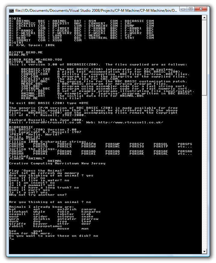
Quite a number of the above routines simply output the value of the accumulator to a port. This is because I'm running CP/M in a Z80 emulator that I've knocked together, and am handling writes to particular ports by implementing the machine-specific operations (such as console input or output) in C#. The floppy disk file system is also emulated in C#; when the program starts, it pulls all the files from a specified directory into an in-memory disk image. Writing to any sector deletes all of the files in this directory then extracts the files from the in-memory virtual disk image back into it. This is not especially efficient, but it works rather well.
To turn this into a working bit of hardware, I intend to replace the C# part with a microcontroller to handle keyboard input, text output and interfacing to an SD card for file storage. It would also be responsible for booting the system by copying the OS to Z80 memory from the SD card. I'm not sure the best way to connect the microcontroller to the Z80, though; disk operations use DMA, which is easy enough, but for lighter tasks such as querying whether console input is available or outputting a character to the display it would be nice to be able to go via I/O ports. A couple of I/O registers may be sufficient as per the current design; a proper Z80 PIO would be even better if I can get my hands on one.
Of more concern is a suitable display; the above screenshot is from an 80-character wide display. Assuming a character was four pixels wide (which is about as narrow as they can be made whilst still being legible) imposes a minimum resolution of 320 pixels horizontally – my current LCD is only 128 pixels wide (not even half way there), and larger ones are really rather expensive!