Integrating the dsPIC33 VDC with the Z80 computer
Saturday, 31st July 2010
The ultimate goal for the video display controller module I have been working on is to drive the display in my Z80 computer project. As I have now got a pretty good set of features I thought it would be a good idea to join the two projects together.
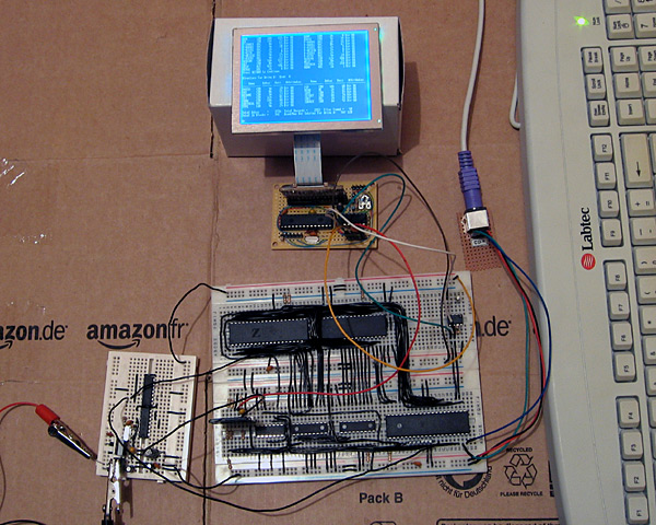
The big board in the lower middle of the above photograph is the main body of the computer, including the Z80, its RAM, the ATmega644P that is used to handle I/O, an SD card for storage and a DS1307 real-time clock. The small board in the bottom left of the photo is the power supply (supplying both 5V and 3.3V) and clock generator (providing a 20MHz and 10MHz clock).
At the top of the photo is the video display controller, connected to a 320×240 graphical LCD. A pin header is used to connect this VDC board to the rest of the computer. Three pins are required for power; 0V, 3.3V (dsPIC33 and output buffer) and 5V (LCD). The VDC is connected to the computer's ATmega644P I/O controller using the two-wire I2C bus (the same bus that is used to access the DS1307 clock). Rather than run a series of graphical demos, the VDC now waits for commands to be written to the I2C slave address 0xEE which it acts on to control what is shown on the screen. I'm aiming for these commands to work in the roughly same way as they did on the BBC Micro VDU, which should make porting the enhanced TI-83+ version of BBC BASIC to this computer a bit easier. The BBC Micro's VDU could be accessed by calling OSWRCH (assuming it was being used as the current output stream), which typically has an address of &FFEE — hence my choice of 0xEE as the I2C slave address!
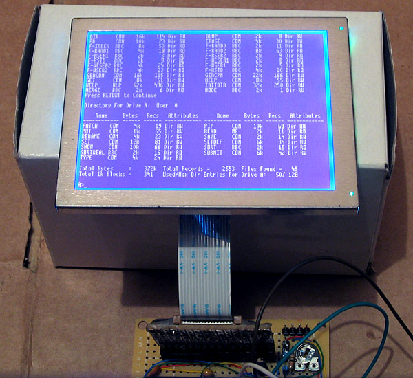
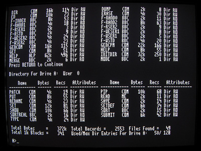
A handful of these VDU commands have been implemented, which is sufficient to run simple CP/M software. The generic CP/M version of BBC BASIC does not, naturally, support any hardware-specific features and as such lacks advanced text or drawing support (one can send commands directly to the output stream with the VDU statement but this isn't very user-friendly). I will need to work on this now that the hardware is coming together! The current VDC code can be downloaded here if you are interested in the changes that have been made.
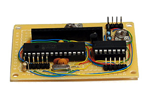
The above photo shows the newly constructed VDC hardware. All of my previous projects have been assembled on stripboard; as the projects have become more complex or simply smaller I've found stripboard to be increasingly awkward to work with. ICs can only really be orientated in one direction, and to reduce the size of circuits I've had to start cutting the tracks between holes (rather than the usual method which is to drill out an entire hole). The supplier I normally acquire parts from, Bitsbox, recently added three different sizes of perfboard to their catalogue so I thought I'd give it a go. I've found it much more pleasant to work with than stripboard, though not as easy to correct if you make a mistake and need to desolder a connection. You can certainly perform some interesting space-saving tricks on the underside of the board!
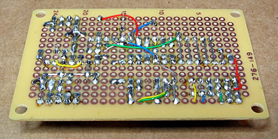
The Kynar insulation on the wire I switched to using also has the advantage of not melting when heated with a soldering iron, as I've had problems in previous projects where tightly-spaced wires will end up getting shorted together as the insulation between them melts.
I have mentioned that one pin header is used to connect the VDC to the computer. There are three others on the board; the two-pin one is for the composite video output, the six-pin one is for connection to a PICkit to reprogram the dsPIC and the four-pin one for the VGA output.
Now that I have moved the VDC onto a permanent circuit board I feel that I can start moving the rest of the computer in the same direction. The software is far from complete and the hardware is pretty rudimentary but it does basically work and having a more robust system to work on should make life a bit easier.
