Simplifying the Light Phaser to Justifier adaptor to a two-chip solution
Saturday, 18th April 2020
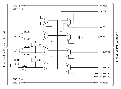
In the previous post I mentioned I was dissatisfied with the optimisation of the Light Phaser to Justifier adaptor circuit. This was because I was using two quad two-input multiplexer chips (eight multiplexers total) but only using three multiplexers on each chip but also needed two inverter gates and so had to add a third chip to accommodate that requirement. It seemed like there must be a better solution, and after pondering this in the shower I think I found it.
One of the inverters is required for the transistor used to drive the TH line from the circuit. The TH line is bidirectional, and from our end of the circuit is either left floating (where it can rise high) or pulled directly to ground. To achieve this I was using an NPN transistor with the collector connected to TH, the emitter connected to ground and the base connected (via a resistor) to our logic signal. Unfortunately, such a transistor is switched on by a positive voltage and so a logic high at the input resulted in a logic low on TH, so to correct this an inverter was added.
A much simpler solution is to get rid of the inverter and transistor entirely and to replace it with a reverse-biased diode, replacing three components with one:
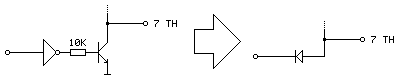
Current can only flow the diode if the voltage at the anode (right, connected to TH) is higher than the voltage at the cathode (left, connected to our logic signal). This means that if our logic signal is the same as the current state as TH then no current flows (and so we leave TH alone) and if our logic signal is high and TH is low then the diode is "backwards" and no current flows. The only way we can influence TH is if it is high and our logic signal is low, allowing current to flow through the diode, grounding TH – which is our desired outcome. One inverter is out of the way!
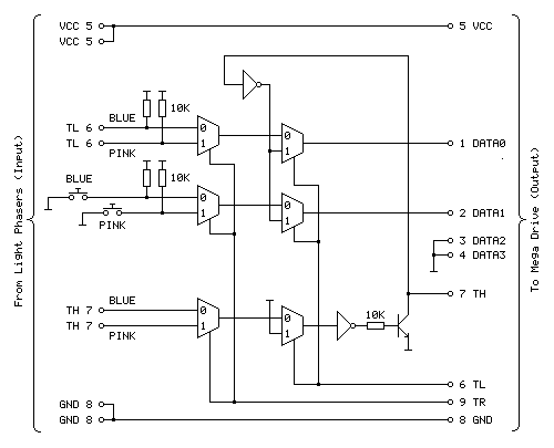
The other inverter is used to produce an inverted version of TH which is used when the console is retrieving the peripheral ID from the Justifier. We can use a multiplexer as an inverter by using the select pin as the input, tying the "0" input high and the "1" input low (that way when 0 is requested 1 is output and when 1 is requested 0 is output). The problem we have here is that all four multiplexers on a chip share a common selection pin, we need to invert TH, and neither of our two multiplexers is using TH as the select pin (one is using TR to select between the two guns and the other is using TL to globally enable or disable the guns).
The solution here is that we only need this inverted TH signal during the peripheral ID check which is carried out when the guns are globally disabled. When the guns are disabled we don't care about what the TR gun-selection multiplexer is doing, as whether the blue gun or pink gun is selected is irrelevant as the data never makes it to the console. We can therefore use the spare multiplexer on the TL-selected multiplexer chip to select between TR and TH, and use the output of this as the select pin into the multiplexer chip previously used to select between the two guns and use its spare multiplexer as the inverter.
The revised circuit is shown above, the wiring is more complicated than the previous one however it takes advantage of all eight multiplexers on both chips and does away with the need to have an additional inverter logic chip and transistor driver circuit for TH.
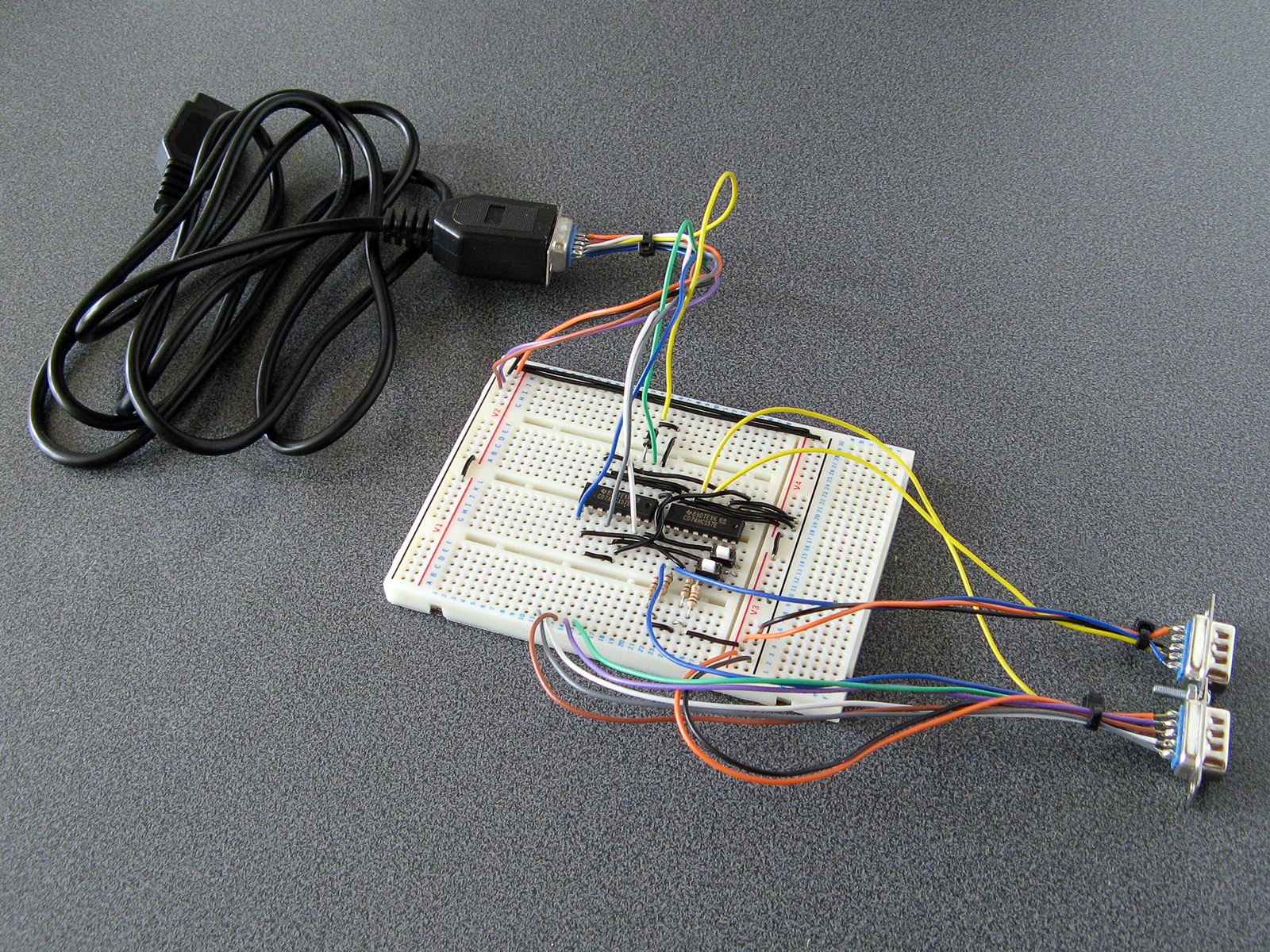
The revised two-chip prototype is picture above, and has been tested successfully with Lethal Enforcers – performance doesn't seem to be any different from before, which seems to be a good sign!