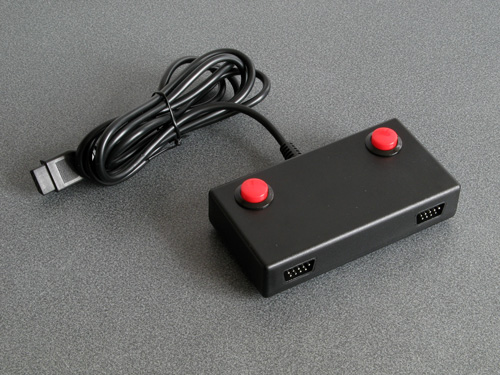
The completed Light Phaser to Justifier adaptor
Wednesday, 29th April 2020
Since my previous post I've had a chance to test the Sega Light Phaser to Konami Justifier adaptor circuit with Lethal Enforcers II: Gun Fighters and it seems to work well throughout the game so I thought it was a good time to put the project into a neat box.
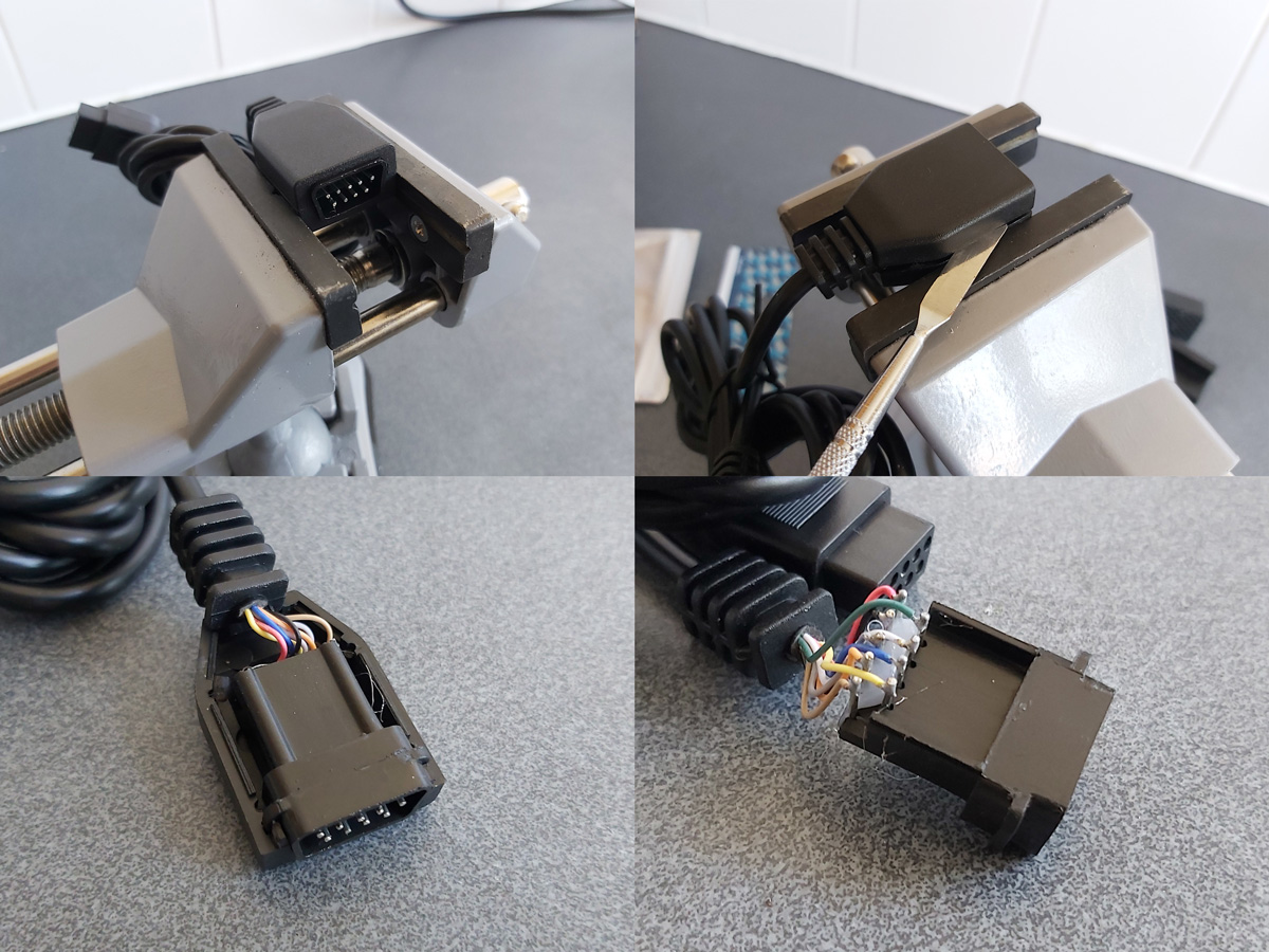
The Mega Drive uses common DE-9 connectors for its controller ports. You can easily find metal connectors with lugs for panel mounting however I wanted to use plastic connectors similar to the ones on the original console – not just for a consistent look, but to also protect the plastic connectors on the Sega Light Phasers from being scratched by the sharp edges of metal connectors. I'm using controller extension cables for the nice moulded connector and cable that plugs into the console, so thought I'd look at the controller socket end. Squeezing the bottom half of the connector splits the two halves apart and you can use a spudger or similar tool to pop the casing open and retrieve the connector – just what I needed!
I nearly always put my projects in off-the-shelf enclosures, cutting and drilling holes in them where required. In this project's case the most awkward holes to cut will be for the controller connectors as they do not have an external lip to mask any poorly-cut holes. As such, I thought I'd start here:
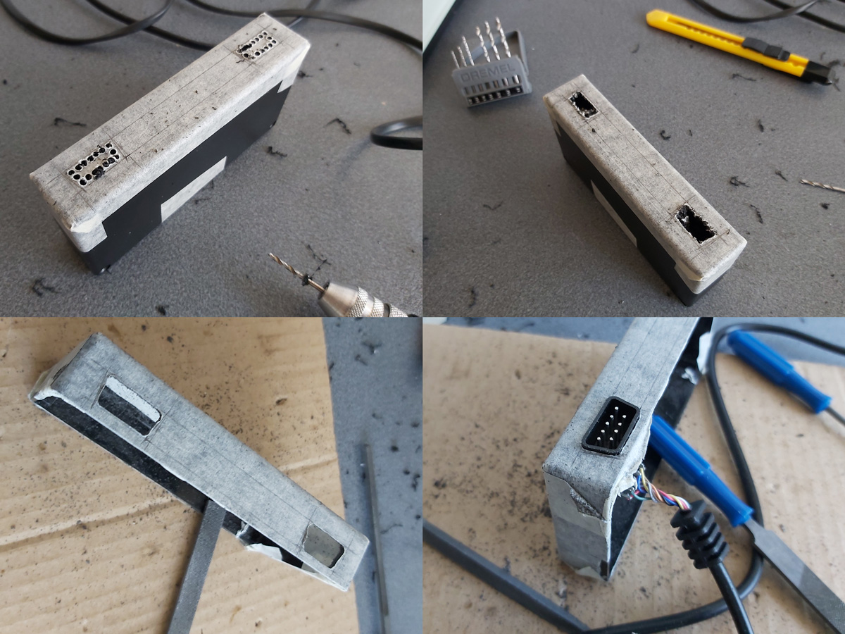
My process here is a bit tedious, but gets the job done – I cover the enclosure in masking tape, then mark out where the holes should appear. I use a drill to make several holes inside the shape I wish to cut out, then use a router bit or sharp knife to cut between the holes to open up the hole properly. A set of hand files is then used to bring the hole to its final shape and size, checking against the connector along the way to ensure an accurate fit.
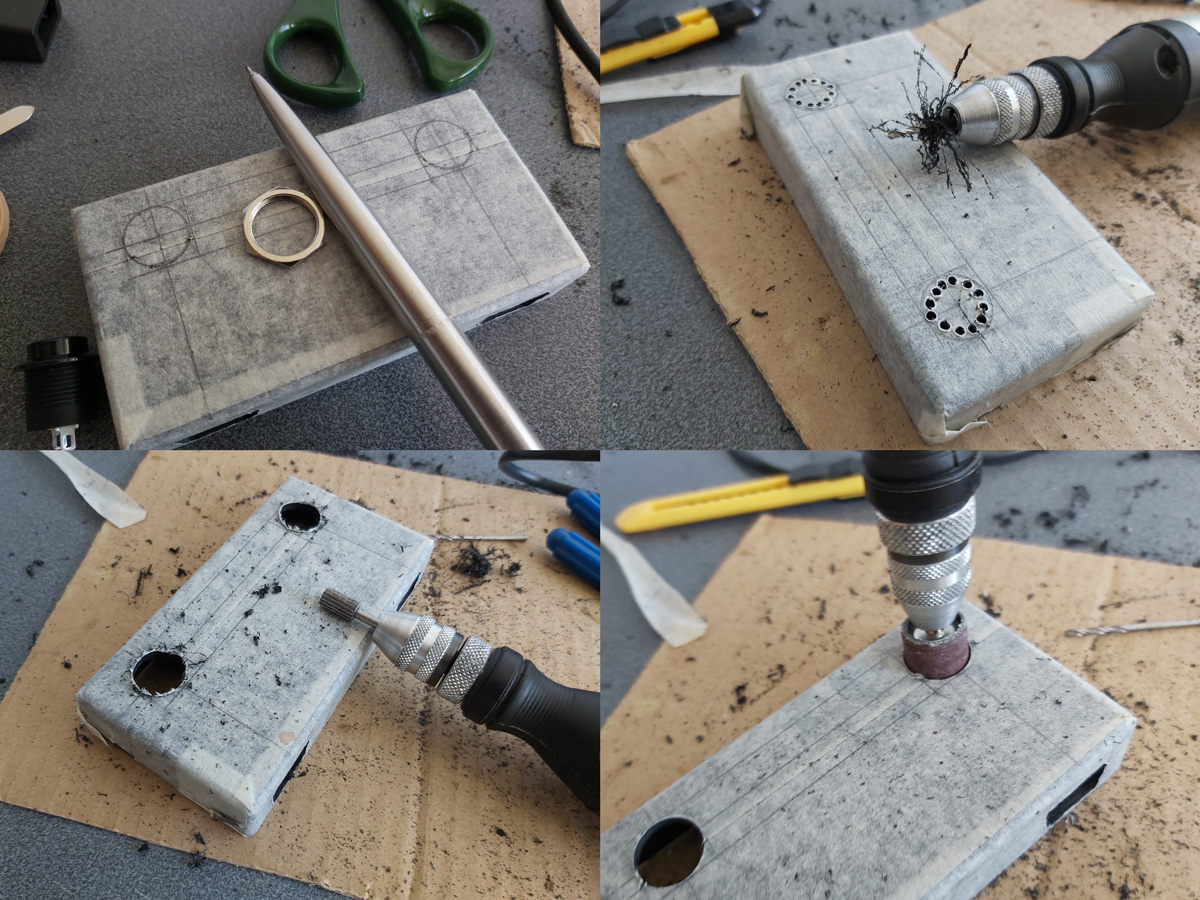
The circular holes for the buttons are cut in a similar fashion, except that as the buttons have outer lips that cover the borders of the hole the outer edges don't need to be quite as precise and a larger router bit and drum sander can speed up the job considerably rather than having to rely on careful hand filing.

A rectangular notch was cut in the rear centre of the case for the cable to the console to exit through and the parts were then loosely installed for a test fit. A piece of pad board was cut to size by scoring it and snapping it over the edge of a table. I wanted it to be as large as possible to make it easier to fit all of the components and wires in, but could the case be closed with the cables and connectors in place too? To make sure it would I thought I'd start with the bulkiest of cables, the one that goes to the console.

I attached a nine-pin crimp connector to the end of the controller cable to plug into the pad board and experimented with the placement of the destination connector – I found that four rows down was about the closest it could go to the top edge of the board whilst still providing enough room for the cable coming in to bend neatly out of the way.
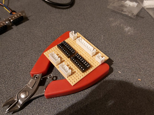
The various parts for the console output connector, light gun input connectors, start button connectors and multiplexer chip DIL sockets were placed on the pad board without soldering to get a rough idea of the final layout and component spacing, ensuring there was enough space around each part to install other components or wires. Once a rough idea was in mind, the main soldering work could begin!
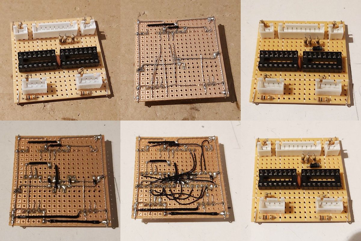
Not much appears to happen between the first and final stages, as most of the work takes place in the wiring on the bottom of the board. Connections that can be made in straight lines without crossing other connections are soldered first, followed by straight connections that cross other connections that can be insulated by slipping on a piece of insulation stripped from a reel of wire. When all of the easy connections are made in this way the outstanding connections are made by soldering lengths of thin wire wrap wire between points on the underside of the board. As each connection is made it is crossed off the circuit diagram – this allows me to check that the circuit diagram is correct, as if I can replicate the circuit from this diagram it's a pretty good indication that it's safe for other people to use to make their own versions of this project.
The DE-9 sockets used for the Light Phaser inputs have all nine pins soldered to the cable by default. We only care about four of them (VCC, GND, TL and TH) and as we don't have enough room for all nine connections to be soldered to the board four-pin connectors are used instead. The old wires are unsoldered and new wires and crimp connectors are attached in their place. This let me check that the circuit board was otherwise working fine, but I still need to figure out how to mount these connectors securely inside the enclosure. I was initially thinking of just holding them in place with hot glue, but this is not very elegant and makes future maintenance much harder! The DE-9 sockets do have a flat surface at the top that is only slightly more than 5mm from the top surface of the enclosure, and I do have some 5mm PCB standoffs that could be handy…
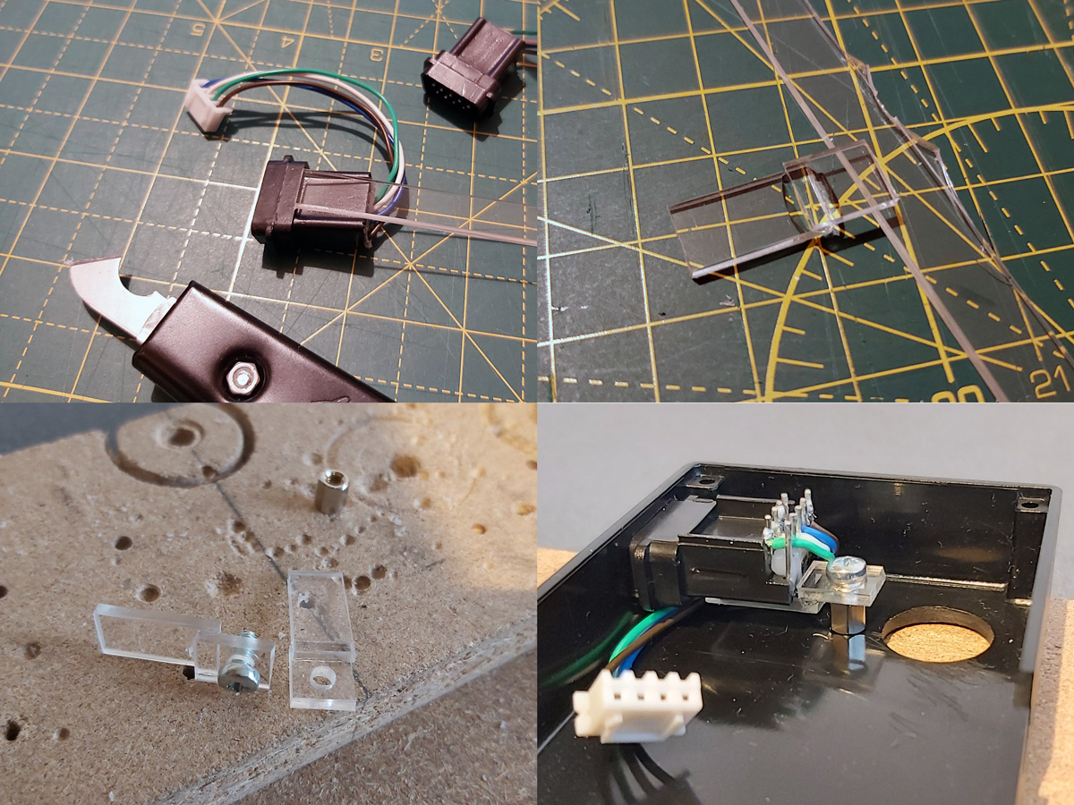
I cut a 9mm wide strip of acrylic from 2mm thick sheet which fits neatly into the top channel of the DE-9 connectors. I then cut it into short sections that could be glued together into Z-shaped brackets. The long section of the "Z" mounts to the DE-9 connector and the short section has a hole drilled through it so it can be secured to the PCB stand-off with a screw. The arrangement is then test fit inside the enclosure using double-sided sticky tape to check that a solid mount is possible – the screw to the PCB stand-off accounts for one part of that mount, and the tight fit of the connector inside the D-shaped hole in the enslosure accounts for the other part.
When it seems like a good fit is possible the Z-shaped brackets are glued to their DE-9 connectors. The DE-9 connectors are then installed in the enclosure with some glue on the bottom of the PCB stand-offs – when everything is lined up neatly this glue secures the stand-offs in the right position, albeit not very strongly.
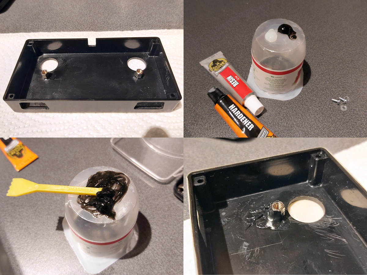
Once the glue had set the screws were removed and the DE-9 sockets were carefully removed. Two-part epoxy was then applied liberally around the PCB stand-offs to provide a bit of extra support. Unfortunately, the stand-offs are very close to the nuts used to secure the start buttons to the enclosure and as such not much epoxy could be placed on that side but hopefully the rest should provide enough support.

Whilst the epoxy was curing the final parts of the project could be assembled – a pair of start buttons had wires soldered to them with crimp connectors on the other end and a couple of rubber strips were cut to provide a bit of extra grip to the bottom of the adaptor. The various component parts of the project can be seen in the photo above.
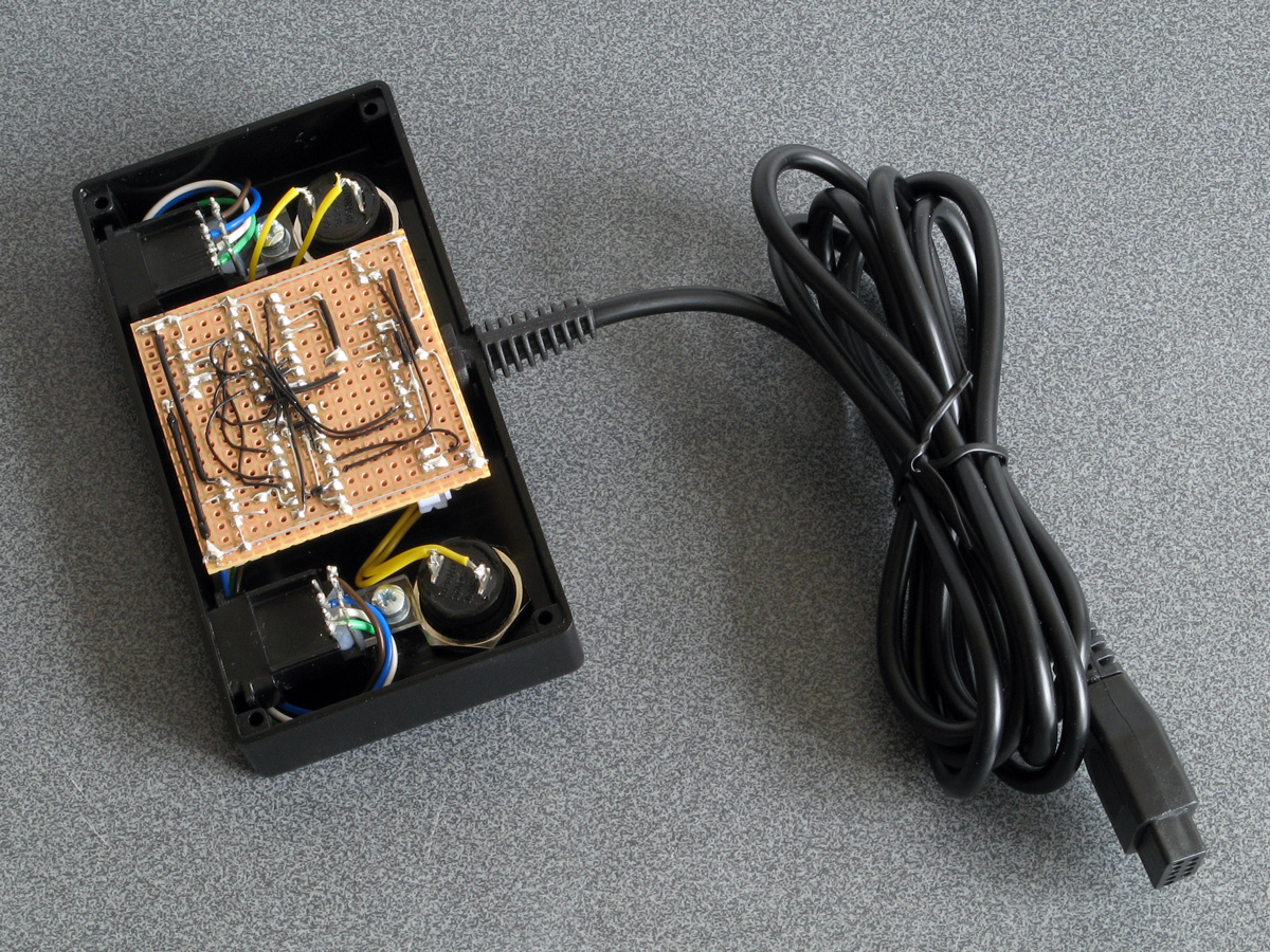
Everything does fit fairly neatly inside the enclosure, fortunately! After everything is assembled inside the bottom of the enclosure was screwed on and the rubber grip strips attached with double-sided sticky tape.
I still haven't been able to test this adaptor with any Mega CD games however it does work well in both Lethal Enforcers and Lethal Enforcers II: Gun Fighters on the stock Mega Drive so hopefully it will also work well in Mega CD games.
I'm pretty happy with how this project turned out. If you would like to assemble the adaptor yourself, you can find the schematic in the previous journal entry, and if you do build it I'd love to hear how you got on!