Map Editing
Wednesday, 26th July 2006
I added five-level grey:
The greyscale effect is optional (adds about 8 lines of code, only runs once per frame and can be disabled with a single switch in the engine package's Settings.inc file.
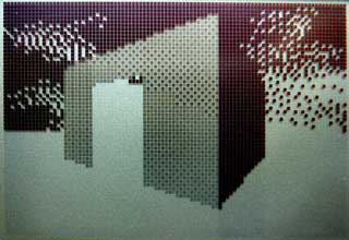
Anyway, I've started throwing together a very primitive level editor. (GDI+)
Insert inserts a new vertex at the mouse location; delete removes the closest vertex. Point at a vertex, hold W, move to another vertex and release W to insert a new wall. (Single-sided, hold shift at the same time to add a double-sided wall). Use D to remove walls in the same way. That sort of thing.
The two different types of wall are represented with white lines (single-sided) and grey lines (double-sided). There are therefore 9 different sectors in the above image.
Imagine that the walls have been kept simple (fixed floor/ceiling heights, single segment) and can have one of 6 different 'colours' - from 0 (invisible/transparent) to 1 (white) through to 3 (50% grey) and finally 5 (black).
Therefore, for the sake of simplicity, assume that all of the double-sided grey walls in the above screenshot are invisible. The room in the south-west of the screenshot is an octogonal room with a doorway in the eastern wall and a square pillar in the middle.
The four double-sided walls in this south-western room are not redundant. You will notice that the level has been cut up into convex sectors. This has one small advantage - it reduces the number of walls that will need to be sorted, as I only need to sort entire sectors for occlusion purposes.
Also, I can see that I can get some sort of portal*-based system up and running. Suppose I use the editor to create this:
If I was to start in the left sector, I would go through and draw each wall. I'd hit the double-sided wall at some point, and know that after this sector I'd have to move into the sector in the middle. After that sector, I'd know that I'd have to move to the sector to the right. With me so far?
Let's do something radical and make that central sector a door, and close it (move the ceiling height down to meet the floor height). This time, when I move through the sectors, I'll hit this sector and see that it's closed. No matter, say I - rather than carry on walking through the sectors, I stop at that point.
By liberally sprinkling a world with doors, and keeping them shut most of the time, you can cut out a fair chunk of geometry. :)
I cannot think of the best way to handle sorting. I don't think I can just use the order in which I wander through the sectors - imagine this:
Imagine you're in the north 'triangle' and looking south. As you can see, you need to travel through more sectors to get to the larger rectangular room than the south triangular room - and using that for sorting is just wrong.
One potential workaround I can think of is that each sector has a visibility list - a list of in which order sectors appear (in front->back order - else we wouldn't be able to take advantage of portals). Problems; MASSIVE amount of data that grows exponentially with each added sector! From what I can also tell, that also seems a precomputed BSP list, done per sector (rather than work out which side of the split to follow each branch, it's already calculated for us). On the other side, this can also be used to calculate (through some nifty ray/plane intersection algorithm) which sectors will NEVER be visible from a particular sector... Hmm. I'm not afraid of 'wasting' RAM with gigantic tables - if we assume a smallish, plain level of 50 sectors, each sector would need a list of at most 49 other sectors. 49*50*2=4900B - not actually too bad. :
(Bah) Just realised that would not work (precomputed sorting based on sectors) at all.
Let's say the red line is your 'view' (not a wall, quick and dirty diagram). It intersects the front of two walls, so it appears that the sort should go north->east->west sectors. However, imagine I move to the other side of the sector and look the same way (mirror the diagram, basically). Now the order goes north->west->east, and I'm still in the same sector :( Do I just clump all the sectors together and sort them all together based on the distance to the central (average) coordinate of each and the camera? (Not fast!)
Thoughts?
*I hope that's the correct word.
Coloured walls and FPS counters
Monday, 17th July 2006
I fixed most of the wall filling code. It now fills by scanline (so is considerably faster), which gives me more flexibility over what I can do with it.
For the moment, I have sacrificed speed with a routine that can handle three different fills - black, white, or 50% dithered. The routine will always blank the wall, mask out the pattern you wish to fill then OR it - which works nicely, but wastes time if you are filling plain black or white walls.
The result is quite pleasing:

As you can also see, I added scrolling skies.
The dithered walls look a bit nicer on hardware. The option to switch the initial dither pattern on alternate frames (resulting in a pseudo-greyscale) can be switched on or off, as it looks rather bad in emulators.
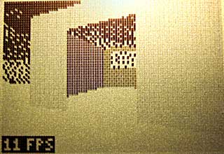
There is one horrible problem with the physical LCD, though - it really cannot cope with columns of alternating pixels. Compare the two shots, one being much closer to the wall (and so having more columns of alternating pixels):
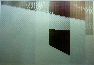
Not so good. Hopefully the world in-game will have enough content to break up the columns, but I'll have to wait and see on that count.
One major concern I've had is keeping the speed of the engine constant. Just moving the player X units per frame is not an option, as the framerate can vary wildly. I need some sort of timing!
Luckily, the calculator has fairly limited timing hardware built-in. I can use this timer via interrupts. There are various pieces of hardware that can trigger interrupts - including the On key, activity on the link IO port (any line held low will trigger an interrupt) or this timer. The TIOS seems to use this timer to scan the keypad a few times a second, so it can read a key and store it for the key reading routines.
Fortunately, it is possible to take advantage of interrupt mode 2 on these calculators to install your own handler. When the engine is initialised, it adds the new handler - which is very simple. All it does is increment a 16-bit counter!
I added a piece of code that read this value and set it to zero each frame, displaying the result (ticks). I then added a piece of code that toggled the data lines of the link IO port, and used a PC program to monitor this rate (I used this technique before to work out interrupt-based timing for the 60Hz CHIP-8 clock). By comparing two extremes - a large viewpoint where I could see all of the walls, close up and a viewpoint where I could see nothing, I could see that one view ran at 16FPS and accounted for 20 ticks, and another ran at 44FPS and accounted for 8 ticks. This shows that one tick is approximately 3ms long, and that a FPS counter could be implemented by dividing 333 by the tick count.
A quick check with my PC program shows that the counter is fairly accurate (close enough for my liking). I can now use these tick counts to scale the movement of the player, so the speed is consistent. Another advantage is that I can set the SE edition calculators to 15MHz, and they can benefit from more fluid framerates (nb: any program I run will still need to run merrily on the 6MHz calcs for me to be happy. I'm not going SE-only!)
That's not to say I can now go and build an exciting level and release a nifty demo. There are still big holes in the engine - simple graphics bugs, like the wall filling code still not supporting top edge slopes with a y difference of over 127: (overflow-related bug)

...to there still not being any proper occlusion (sorting)...

I'd like to get occlusion up and running, so I can throw a nifty level together (for example, showing off non-90° walls). Thing is, it's tricky trying to show off cool stuff and not walk into an area where you can see the world isn't quite as solid as it should be. 
Filling
Friday, 7th July 2006

I chucked some simple filling in to the engine as a test. It scans along the top and bottom edges of the shape, then fills columns. This is rather inefficient (filling scanlines is much faster - the screen is shorter than it is wide, so tracing Ys for the boundaries is faster than scanning Xs, and when filling by scanline you can write 8 pixels - a byte - in a single shot) but it served the purpose of a quick demo. It's rather broken, and doesn't match the lines correctly (so there are slight gaps and overflows). It's only temporary.
I'd like to extend the filling to support different dithered fills - white, 25%, 50%, 75% and black walls would look nice.
There is no sorting as yet, I just arranged the walls in back-to-front order in the level file.
@philipptr: I don't know if you ever completed your triangle filling, but the way I've done it in the past is to split the triangle into two halves (y0→y1 and y1→y2, where y0<y1<y2). I would then trace down the sides of the triangle, calcuating the X bounds for the top and bottom halves (Bresenham), then filling in the horizontal lines using these values. Only uses integer arithmetic, so nice and fast.
Whether this will be turned into a game or not depends on whether I can get it to scale sensibly with decent-sized levels; especially with the addition of scaled sprites. If I can get a nice sized level that you can walk around nicely, then I'll try and add a game - pointless planning a game around an engine that isn't up to par!
Clipping works! (Almost)
Monday, 3rd July 2006
Clipping now works in nearly all cases:

One of the problems was lack of precision. Here's the typical case that worked, running in my mockup:
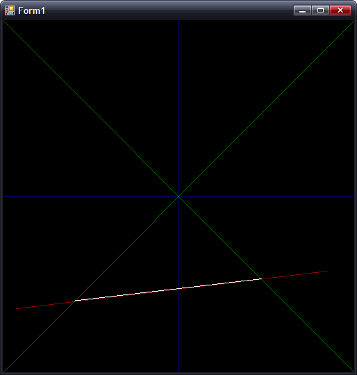
In this case, where |dX| > |dY|, all is good. However, switch that around so that |dY| > |dX|, and you get the following:
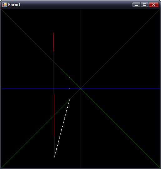
(Fixed point isn't so good for holding values that tend towards infinity). The solution is to have two branches for the clipping arithmetic, switching to the alternative form when |dY| > |dX|.
Preparation:
m = (Y1 - Y0) ÷ (X0 - X1) ; m is negative gradient.
c = Y0 + m × X0 ; Not sure what to call this, but it's used in all the below calculations
Clipping to y = 0:
x = c ÷ m
y = 0
Clipping to y = +x:
y = c ÷ (1 + m)
x = +y ; not used as we can skip having to transform.
Clipping to y = -x:
y = c ÷ (1 - m)
x = -y ; not used as we can skip having to transform.
The reason for clipping to y = 0 is to make sure the line is clipped to the correct side.
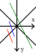
If you look at the red and blue lines, you can see that the far out-of-range points both have x < 0. This indicates that you should clip to y = -x. However, the green line also has the far end at x < 0, but we actually need to clip to y = +x. We can fix this problem by first clipping to y = 0, then checking the sign of x.
To fix the steep gradient problem, I just need to switch to these alternative sums:
First up, the gradient and c are calculated as:
m = (X0 - X1) ÷ (Y1 - Y0) ; Flipped
c = X0 + m × Y0 ; Again, X/Y flipped.
For clipping to y = 0:
x = c ; No need to divide by m!
The only other difference is to make sure that when clipping y = -x:
y = c ÷ (m - 1) ; as opposed to (1 - m)
...and all is hunky-dory.
The only remaining problem is if you are positioned directly inside a wall, which collision detection should fix.