Cylinders and translucent surfaces
Tuesday, 29th April 2008
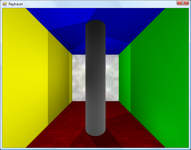
The first addition to the raytracer was a cylindrical surface, represented by two end points and a radius. In the two screenshots above, the cylinder is infinitely long - not very useful. However, by calculating the point on the cylinder's axis that is closest to the struck point on its surface you can work out how far along its axis you are, and from that whether you are between either of the cylinder's ends.
The cylinder can have its ends optionally capped. To add the caps, you can create plane that has a normal that points in the the direction of the cylinder's axis. If you collide with the plane, you can then calculate the distance between the point you struck on it and the end coordinate of the cylinder. If this distance is smaller than the radius of the cylinder, you've hit one of the end caps.
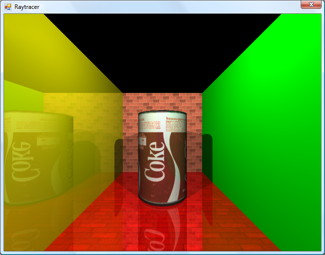
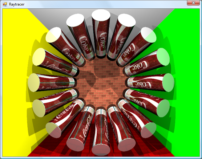
Texturing the cylinders proved rather difficult. The v component of the texture component can be calculated by working how far along the cylinder's axis you are - easy. However, to wrap a texture around the rotational axis of the cylinder is a bit more complicated. In the first screenshot, I simply used Math.Atan2(z,x) to get the angle, and hence texture coordinate - but this only works if the cylinder points along the y axis. If I had another vector that lay perpendicular to the cylinder's axis I could use the dot product to work out its angle, but I don't. The cross product could generate one, but I'd need another vector to cross the axis with... In the end, this post came to my rescue, and I managed to get it working for cylinders pointing along any axis - producing the second screenshot.
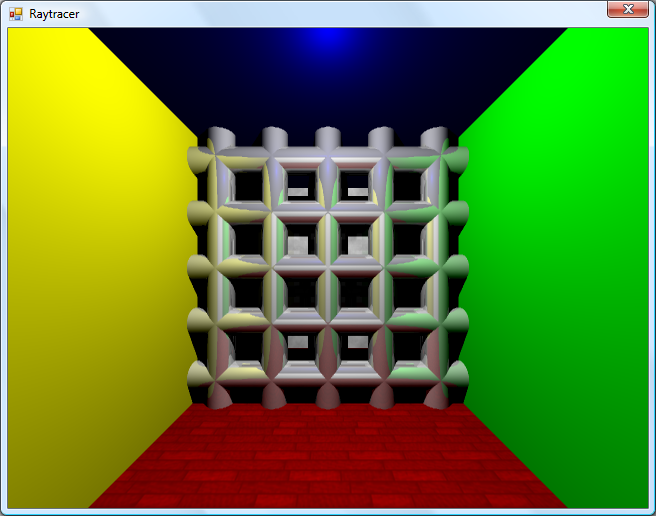
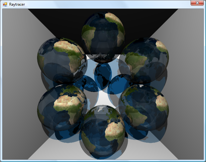
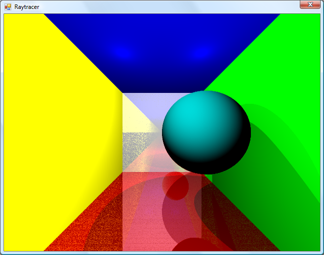
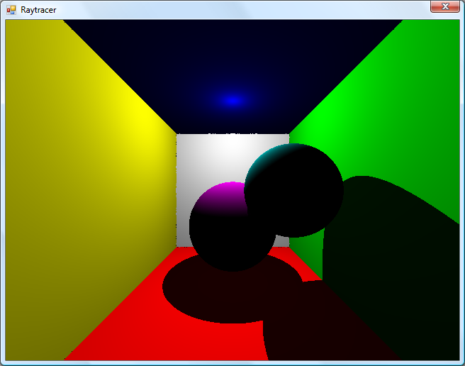
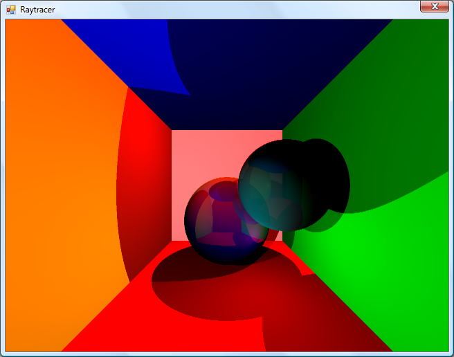
An addition I've wanted to make for a while was support for translucent surfaces.
This required a few changes to the structure of the raytracer. Previously, all methods for calculating ray intersections had to return a single Collision object, which contained a boolean flag specifying whether the collision was succesful. A translucent sphere would need to return two collision points - one as the ray enters the front and one as it leaves the back of its surface. To this end, all collision detection methods now return an array (empty or null if no collisions were made), and each collision has a flag indicating whether the collision was made by the ray entering the solid or leaving the solid (this is required, for example, to invert surface normals for correct shading).
Once the nearest struck point to the camera has been handled (including recursive reflection-handling code) it is checked to see if it's on a translucent surface. If so, the raytracer continues raytracing away from the camera, and blends the new result with the existing result based on its opacity. By stopping and starting again, one can adjust the direction of the ray - for example, to add a refraction effect (which I have not yet got working  ).
).
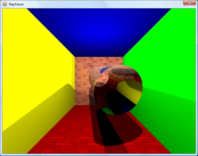
One trick the above image misses is that it's still simply scaling down the intensity of the light by the opacity of the surface it passes through. It would look nicer if the light was coloured by the surface it passes through; so, in the above example, the white light shining through the blue water on the sphere should cast blue-tinted shadows.
Whilst it's far from being real-time, I can still make it dump out a sequence of frames to create a basic animation.

Fixed reflections and proper textures
Sunday, 27th April 2008
How long does that scene take to render?
Just over a minute, so not very good performance at all. I've made some changes since then (including multithreading) that drop it down to about 30 seconds.
There is definitely something wrong with the reflections.
I decided to rewrite the main raycasting code from scratch, after seeing results such as the above. I'm not sure where the speckles were coming from, nor why the reflections were being calculated incorrectly. The new code writes to regions of an array of integers (for 32-bit ARGB output), and is designed much more simply. By splitting the output buffer into two halves I can perform the raytracing in two threads, which makes much better use of modern dual-core CPUs.

Before and after rewrite.
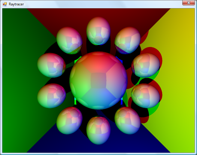
A scene with lots of reflective spheres would seem like a good test. If you look at the reflections in the outer ring of spheres, they're quite different (and now appear to be correct) now, so whatever was wrong now seems to have been fixed.
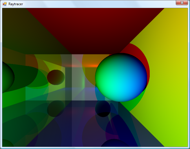
A similar scene to the one at the top of this entry.
A scene with multiple reflective planes no longer appears to have the noise and reflection bugs that were clearly visible in the first screenshot in this entry.
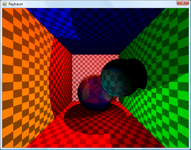
Textures would certainly make the objects look a bit more interesting, but I couldn't think of a simple way of aligning a texture to a surface. I decided that textures should be treated as simple 2D rectangles, and each material can now have a diffuse texture applied to it (which provides a method Colour GetColour(Vector2 coordinate) to read it). To attach the texture to the surface of an object the surface needs to implement ITexturable, which exposes the method Vector2 GetTextureCoordinate(Vector3 surfacePoint).
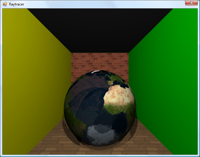
In short; it's the job of the surface class (such as the Sphere or Plane classes) to map the struck point to a texture coordinate. This is most easily handled with the sphere, which simply converts the cartesian coordinates of the stuck point to polar coordinates.
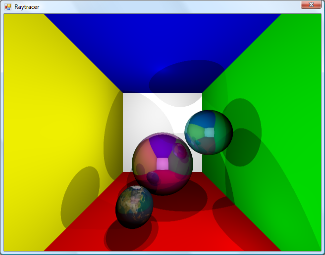
The small foreground sphere has an Earth texture.
For planes, I thought that the easiest way of aligning the texture would be to declare two vectors - one that represents the texture's X axis and one that represents the texture's Y axis.
For example, take the white wall at the back of the room in the above screenshot. To align a texture parallel to its surface, one could set the texture's X axis vector to point right and its Y axis vector to point down. By changing the magnitude of these vectors the texture can be scaled.
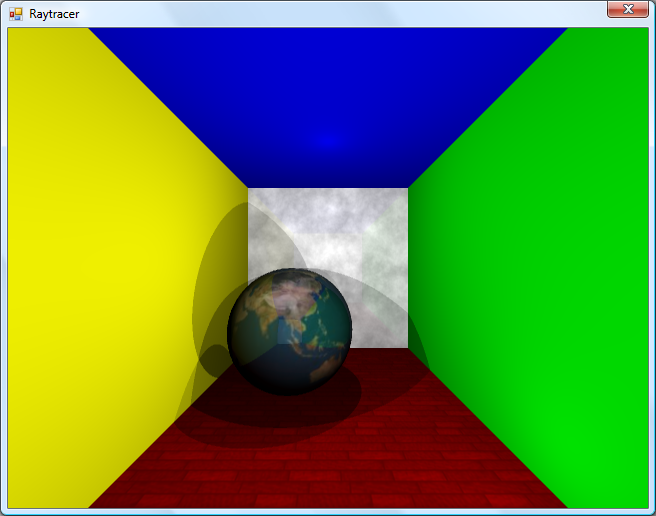
The back wall and floor are textured planes.
For the floor in the above image, the texture's X axis points right, and its Y axis points into the screen.
As the texture merely has to provide a method that takes in a texture coordinate and outputs a colour, this lets us declare simple procedural textures.
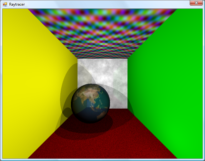
The floor and ceiling textures are procedurally generated.
The rather garish ceiling is declared like this in code:
this.Tracer.Objects.Add(new WorldObject() {
	Surface = new Plane(Vector3.Down, 10.0d) {
		TextureXAxis = Vector3.Right,
		TextureYAxis = Vector3.Forward,
	},
	Material = new Material() {
		Colour = Colour.White,
		Texture = new ProceduralTexture(
			p => new Colour(
				1.0d,
				(Math.Sin(p.X) * Math.Cos(p.Y * 2)) / 2.0d + 0.5d,
				(Math.Cos(p.X) * Math.Sin(p.Y * 3)) / 2.0d + 0.5d,
				(Math.Sin(p.X * 5) * Math.Sin(p.Y / 0.3d)) / 2.0d + 0.5d
			)
		),
	},
});
I think before I go any further I'm going to need to support a wider variety of surfaces than spheres and planes. Another limitation with the existing implementation is that only a single collision between a ray and a surface is reported, which limits what can be done with the renderer - for example, a glass sphere that refracts a ray that passes through it would need to report two collisions, one for the front of the sphere as the ray passes through and again one for the back as the ray leaves.
Raytraced shadows, reflections and chessboards
Saturday, 26th April 2008
I thought that better lighting might help the scene look a bit nicer, so decided removed all the existing lighting code (and reflection code, to make life easier) and tried to add some basic shadowing.

Simple shadowing test.
When a ray's intersection with the world is found, a ray is cast back from that point towards the light source. If this ray collides with another object on its return trip to the light, it's assumed that it's in the shade. In the above test, points in shade simply had their diffuse colour divided by two. This still looks rather flat, though.
As we know the surface normal of the surface that has been struck and the direction of the ray that's going between the struck point and the light source, we can work out how much the surface point is facing the light by taking the dot product of the two vectors. When multiplied by the surface's diffuse colour, this results in much smoother lighting.
Each colour value is multiplied by the dot product of the light beam and the surface normal.
That's better, but would look better with multiple lights. I start with a running total colour (initially black), then iterate over a list of lights. If the struck point is in line with the light, I add the surface diffuse colour multiplied by the light colour to this running total. This results in a much more interesting-looking scene.
Multiple lighting test - two white and one red light, all in different positions.
The edges of the surfaces are rather ugly and noisy, probably due to rounding errors. They are helped if I offset the pixel coordinates by 0.5 (so the rays are shot through the centre of pixels, rather than the top-left corner), but proper supersampling would probably look better.

Rendering with 4x supersampling.
It does, thankfully, at the expense of making the rendering time four times longer!
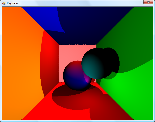
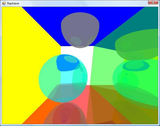
Reintroduction of reflective surface support.
I reintroduced the reflective surfaces - those reflections don't look quite right to me, but I can't really tell. More detail in the world might make it easier, so I'd like to add some sort of texturing.
The obligatory chessboard texture.
I'm undecided how to handle mapping struck points to texture coordinates. For the moment I'm just XORing together the x, y and z components together - if the least significant bit of the result is zero, return half of the diffuse colour, otherwise return the full diffuse colour.
Raytracing - Beware of the coder colours
Friday, 25th April 2008
As much as I claim to be interested in software rendering (be it as part of a game engine or as an effect in a demo), I've never actually written a raytracer. Having written some basic vector and plane arithmetic code for physics in the XNA Quake project, I thought I'd give it a stab.
No apologies made for the coder colours.
Currently, the world is just a simple List<WorldObject>, where each WorldObject has a Surface and Material property. The Surface has to implement IRayCollidable, which lets me call GetCollision(Ray) on it to find out where a ray strikes it (if at all), returning the point of collision and the normal of the surface that was hit. Currently, there are only two types that implement this interface - Plane and Sphere - but they'll do for testing.
For each ray, I iterate over the list of items in the world and grab the collision point. If a collision is made, I add the details to another list (including the total length of the ray at this point) and, if the surface's material is marked as reflective (ie, has a Reflectivity property greater than zero) I reflect the ray against the surface normal and cast again (recursively, so it's very easy to cause a StackOverflowException when two shiny surfaces are parallel to eachother).
Once I have a record of all the collisions, I sort them in back-to-front order based on the length of the ray, then iterate over them, blending the colours as I go (so a reflection in a green surface ends up being green tinted).

Marginally less garish.
To try and get a better sense of the 3D scene, I added a simple directional light. This simply takes the dot product of the hit surface normal and the light's direction, then multiplies it by the material's diffuse colour. The above screenshot has a light pointing directly away from the camera, hence the upper and left walls are completely black (however, the bottom and right walls, being reflective, are partially visible).
I've trying to do this without looking up the correct way of doing it, experimenting as I go - mainly in an attempt to try and patch up my rather poor handle on 3D maths and collision detection.
SC-3000 keyboard and a final release
Sunday, 20th April 2008
The latest addition to Cogwheel is SC-3000 keyboard emulation.
The SC-3000 was a home computer with similar hardware to the SG-1000 console, with the main addition of a keyboard. Software cartridges could add, for example, BASIC programming capabilities.
Due to lack of time and motivation, and the fact that the emulator is pretty much as good as I'm going to get it at this moment in time, I've removed the beta label and uploaded the latest version to its website.
3D glasses and CPU cycle counting
Monday, 7th April 2008
I reintroduced joystick support to the emulator front-end over the weekend, using a much more sensible input manager. The control editor form uses the same interface design for keyboard and joysticks - you click the button you wish to edit, it appears pressed, you press the key (or joystick button) you wish to bind to it and it pops back out again. It'll also check to see if you've moved the joystick in a particular direction on any of its reported axes.
Another feature I added was better support for games that used the 3D glasses, using a simple red-cyan anaglyph output blender.
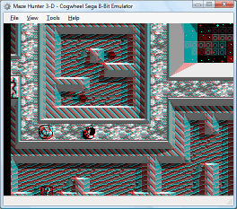
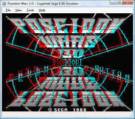
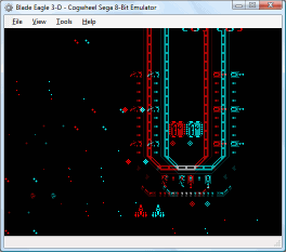
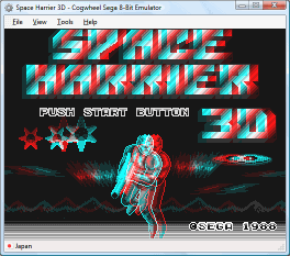
If the memory address range that the glasses respond to has been written to within the last three frames, it switches to the blending mode.
Irritatingly, with one glaring bug fix I managed to lower overall compatibility. Some instructions weren't being timed correctly (or at all) meaning that the emulator was executing too many instructions for the number of clock cycles it was asked to run. During the time each video scanline is run, 228 CPU cycles are executed. Upping this to 248 cycles (just for experimentation) fixes all known bugs - including the long-standing flickering pixels at the top of the screen in Cosmic Spacehead and display corruption in GP Rider. (However, digitised speech plays at a noticably higher pitch).
I'm not entirely sure why this is - it could be that some instructions are claiming to take too long, it could be yet another interrupt problem. To call this mildly frustrating is a bit of an understatement!
ColecoVision and TMS9918 Multicolor
Thursday, 3rd April 2008
One notable gap in my TMS9918 (video) emulation was its "Multicolor" mode. This mode broke the screen down into 4×4 pixel squares, resulting in a 64×48 grid. Each cell could be assigned a unique colour, giving you a crude bitmapped video mode.
No Master System or SG-1000 software used this mode to my knowledge, which reduced the likelihood of it being supported at all (if I could't test it, how could I emulate it?) I was tipped off that some ColecoVision software made use of it, so set about emulating the ColecoVision.
The ColecoVision hardware is very similar to the SG-1000 in terms of what is inside the case - a Z80 CPU, TMS9918 video and SN76489 sound. The memory map (as in, which address ranges map to which memory devices) is different, as is the I/O map (as in, the I/O ports that the various hardware components are connected to). To handle this case, the emulator now has a Family field, which can be set to Sega or ColecoVision. This controls which of the different mappings it uses for memory and hardware I/O.
Another difference is the presence of a BIOS ROM. The Sega Master System and Sega Game Gear consoles had the option of BIOS ROMs, but all these did was very basic initialisation and header/checksum checking. The ColecoVision, however, has an 8KB BIOS ROM that offers a lot of functionality to the programmer, so this must be present to run most ColecoVision games.
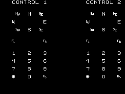
The controllers are also quite different. As well as the typical eight-direction joystick and two fire buttons, it added a 12-key keypad (0-9, * and #). This many keys is making my InputManager class look thoroughly idiotic, so that will certainly need a rewrite.
Apart from that, it's pretty simple. RAM is 1KB instead of 8KB; the sound generator uses the standard 15-bit wide shift register (instead of the 16-bit wide one used in the SMS); the video display processor interrupt output is connected to NMI rather than INT.
With those differences applied, it's easy to add the few lines of code to emulate the Multicolor video mode.
Smurf Paint 'n' Play Workshop
ColecoVision emulation has not been tested at all thoroughly, so chances are it doesn't work very well; Multicolor emulation has been tested with precisely one game!
You can download the latest build of Cogwheel from its website, featuring the new ColecoVision emulation.