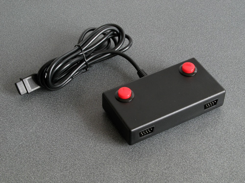
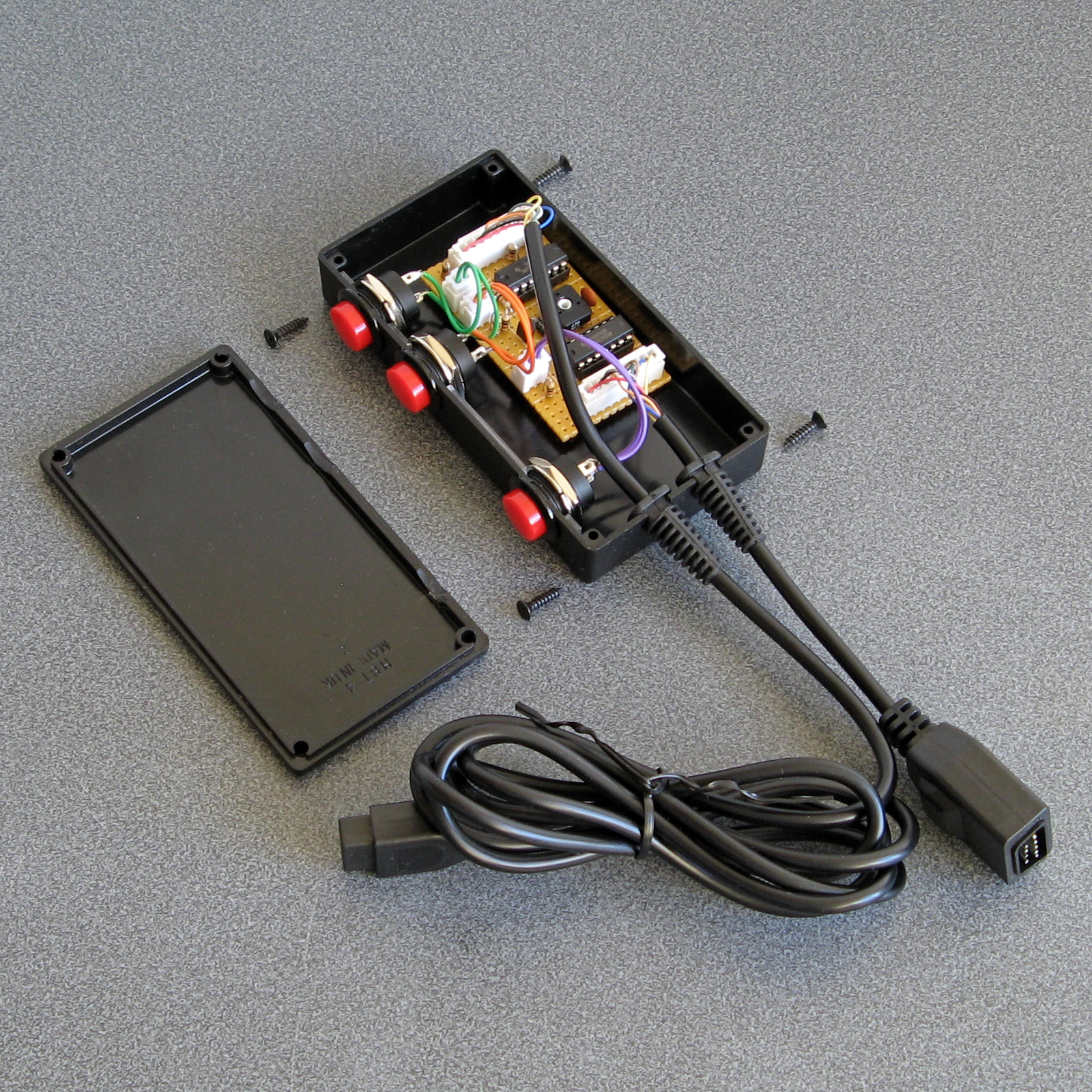
The completed Light Phaser to Justifier adaptor
Wednesday, 29th April 2020
Since my previous post I've had a chance to test the Sega Light Phaser to Konami Justifier adaptor circuit with Lethal Enforcers II: Gun Fighters and it seems to work well throughout the game so I thought it was a good time to put the project into a neat box.
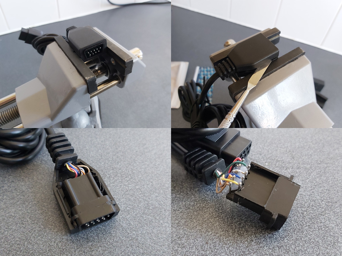
The Mega Drive uses common DE-9 connectors for its controller ports. You can easily find metal connectors with lugs for panel mounting however I wanted to use plastic connectors similar to the ones on the original console – not just for a consistent look, but to also protect the plastic connectors on the Sega Light Phasers from being scratched by the sharp edges of metal connectors. I'm using controller extension cables for the nice moulded connector and cable that plugs into the console, so thought I'd look at the controller socket end. Squeezing the bottom half of the connector splits the two halves apart and you can use a spudger or similar tool to pop the casing open and retrieve the connector – just what I needed!
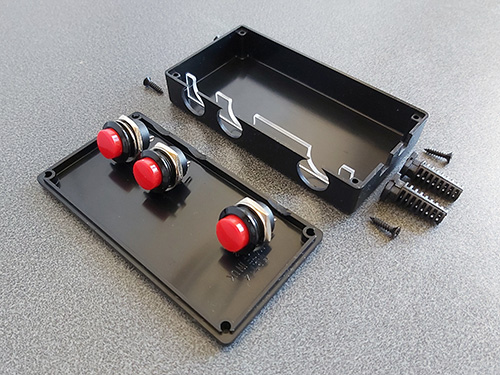
I nearly always put my projects in off-the-shelf enclosures, cutting and drilling holes in them where required. In this project's case the most awkward holes to cut will be for the controller connectors as they do not have an external lip to mask any poorly-cut holes. As such, I thought I'd start here:
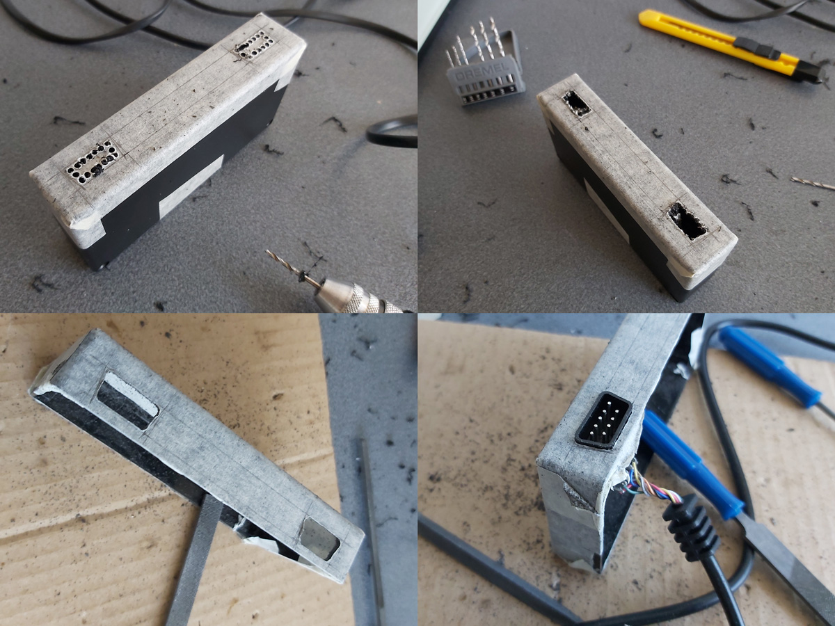
My process here is a bit tedious, but gets the job done – I cover the enclosure in masking tape, then mark out where the holes should appear. I use a drill to make several holes inside the shape I wish to cut out, then use a router bit or sharp knife to cut between the holes to open up the hole properly. A set of hand files is then used to bring the hole to its final shape and size, checking against the connector along the way to ensure an accurate fit.
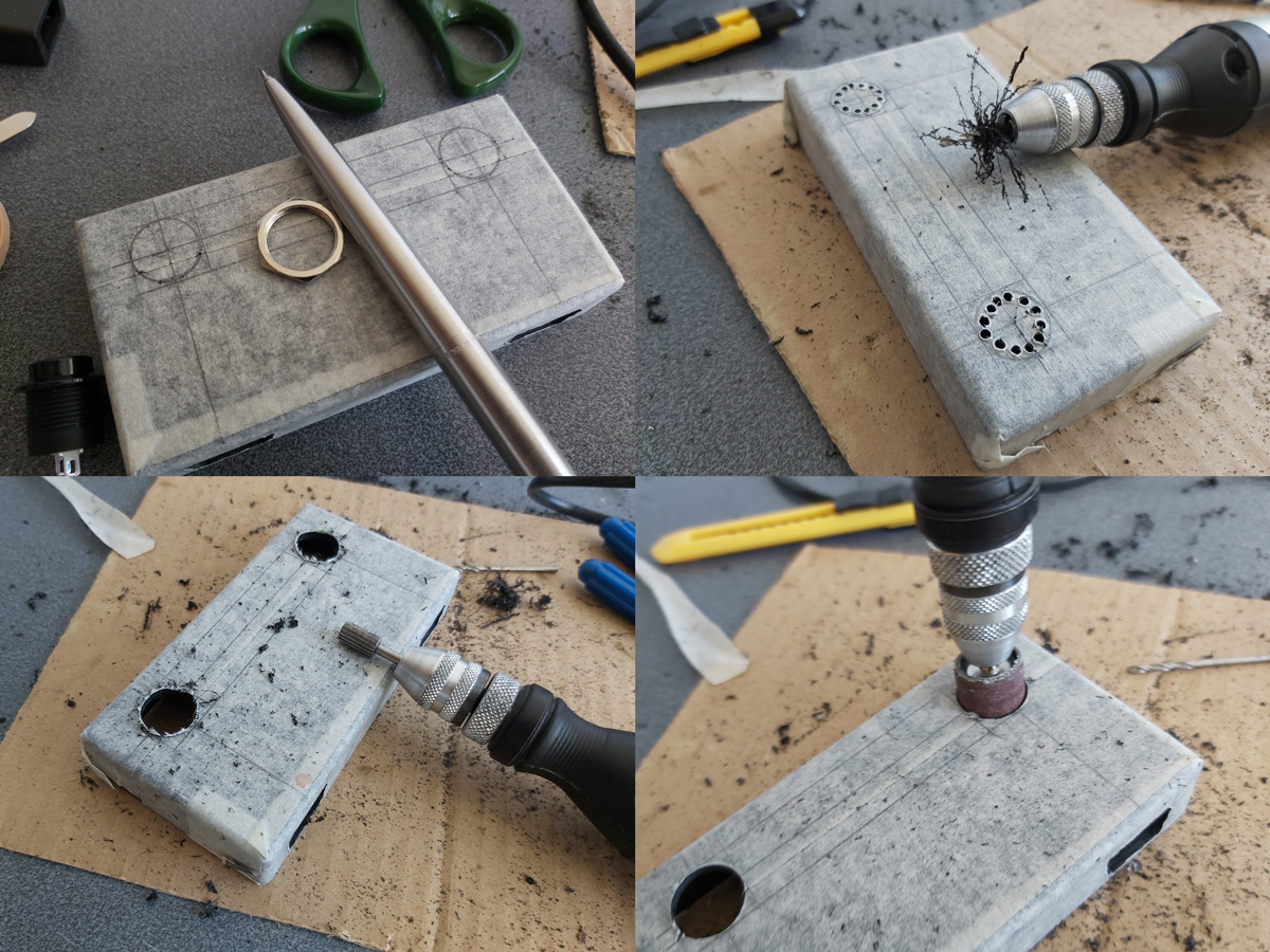
The circular holes for the buttons are cut in a similar fashion, except that as the buttons have outer lips that cover the borders of the hole the outer edges don't need to be quite as precise and a larger router bit and drum sander can speed up the job considerably rather than having to rely on careful hand filing.

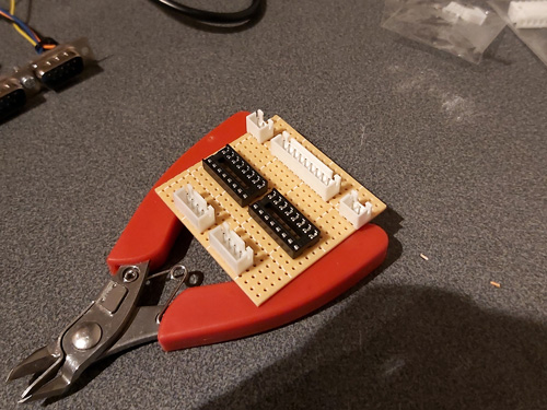
A rectangular notch was cut in the rear centre of the case for the cable to the console to exit through and the parts were then loosely installed for a test fit. A piece of pad board was cut to size by scoring it and snapping it over the edge of a table. I wanted it to be as large as possible to make it easier to fit all of the components and wires in, but could the case be closed with the cables and connectors in place too? To make sure it would I thought I'd start with the bulkiest of cables, the one that goes to the console.

I attached a nine-pin crimp connector to the end of the controller cable to plug into the pad board and experimented with the placement of the destination connector – I found that four rows down was about the closest it could go to the top edge of the board whilst still providing enough room for the cable coming in to bend neatly out of the way.
The various parts for the console output connector, light gun input connectors, start button connectors and multiplexer chip DIL sockets were placed on the pad board without soldering to get a rough idea of the final layout and component spacing, ensuring there was enough space around each part to install other components or wires. Once a rough idea was in mind, the main soldering work could begin!
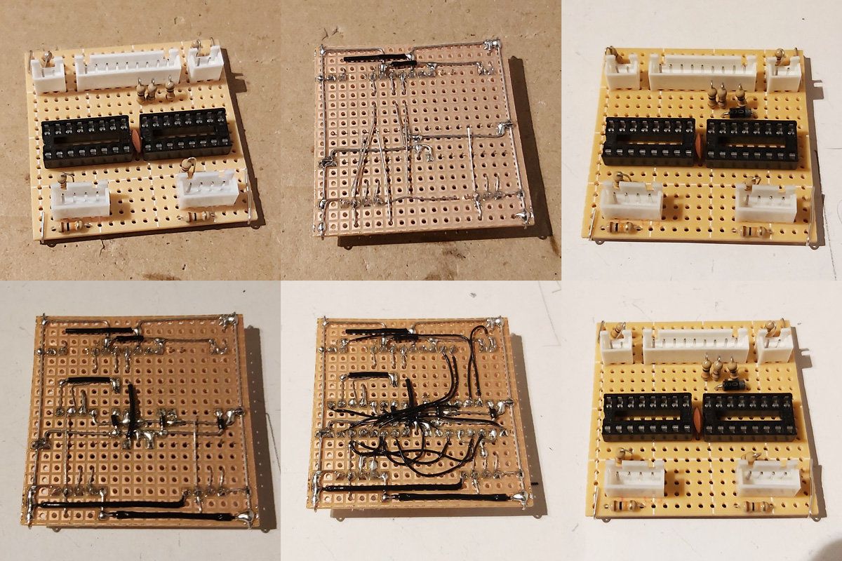
Not much appears to happen between the first and final stages, as most of the work takes place in the wiring on the bottom of the board. Connections that can be made in straight lines without crossing other connections are soldered first, followed by straight connections that cross other connections that can be insulated by slipping on a piece of insulation stripped from a reel of wire. When all of the easy connections are made in this way the outstanding connections are made by soldering lengths of thin wire wrap wire between points on the underside of the board. As each connection is made it is crossed off the circuit diagram – this allows me to check that the circuit diagram is correct, as if I can replicate the circuit from this diagram it's a pretty good indication that it's safe for other people to use to make their own versions of this project.
The DE-9 sockets used for the Light Phaser inputs have all nine pins soldered to the cable by default. We only care about four of them (VCC, GND, TL and TH) and as we don't have enough room for all nine connections to be soldered to the board four-pin connectors are used instead. The old wires are unsoldered and new wires and crimp connectors are attached in their place. This let me check that the circuit board was otherwise working fine, but I still need to figure out how to mount these connectors securely inside the enclosure. I was initially thinking of just holding them in place with hot glue, but this is not very elegant and makes future maintenance much harder! The DE-9 sockets do have a flat surface at the top that is only slightly more than 5mm from the top surface of the enclosure, and I do have some 5mm PCB standoffs that could be handy…
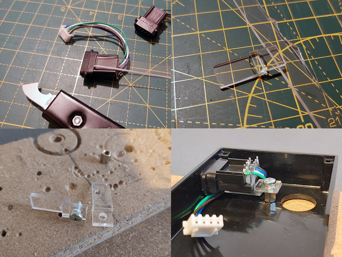
I cut a 9mm wide strip of acrylic from 2mm thick sheet which fits neatly into the top channel of the DE-9 connectors. I then cut it into short sections that could be glued together into Z-shaped brackets. The long section of the "Z" mounts to the DE-9 connector and the short section has a hole drilled through it so it can be secured to the PCB stand-off with a screw. The arrangement is then test fit inside the enclosure using double-sided sticky tape to check that a solid mount is possible – the screw to the PCB stand-off accounts for one part of that mount, and the tight fit of the connector inside the D-shaped hole in the enslosure accounts for the other part.
When it seems like a good fit is possible the Z-shaped brackets are glued to their DE-9 connectors. The DE-9 connectors are then installed in the enclosure with some glue on the bottom of the PCB stand-offs – when everything is lined up neatly this glue secures the stand-offs in the right position, albeit not very strongly.
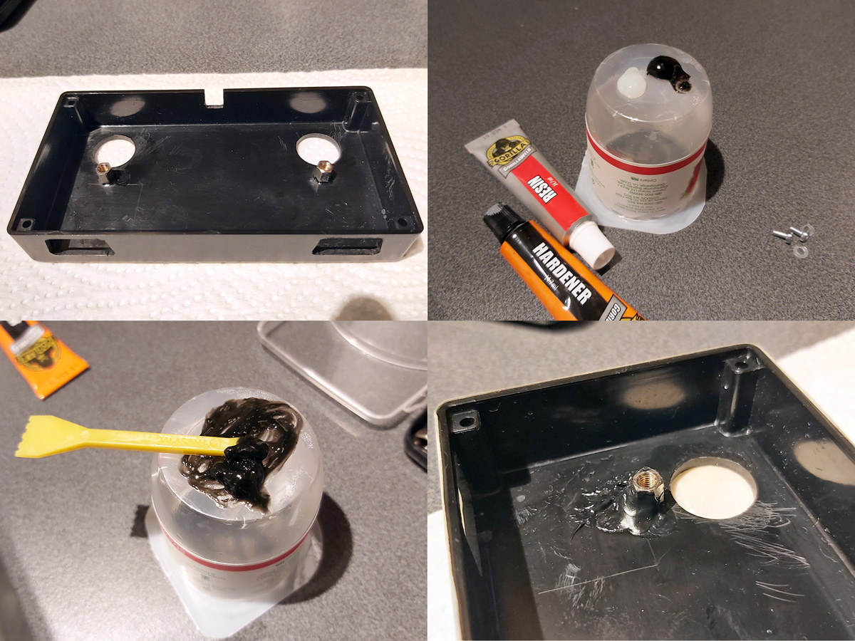
Once the glue had set the screws were removed and the DE-9 sockets were carefully removed. Two-part epoxy was then applied liberally around the PCB stand-offs to provide a bit of extra support. Unfortunately, the stand-offs are very close to the nuts used to secure the start buttons to the enclosure and as such not much epoxy could be placed on that side but hopefully the rest should provide enough support.

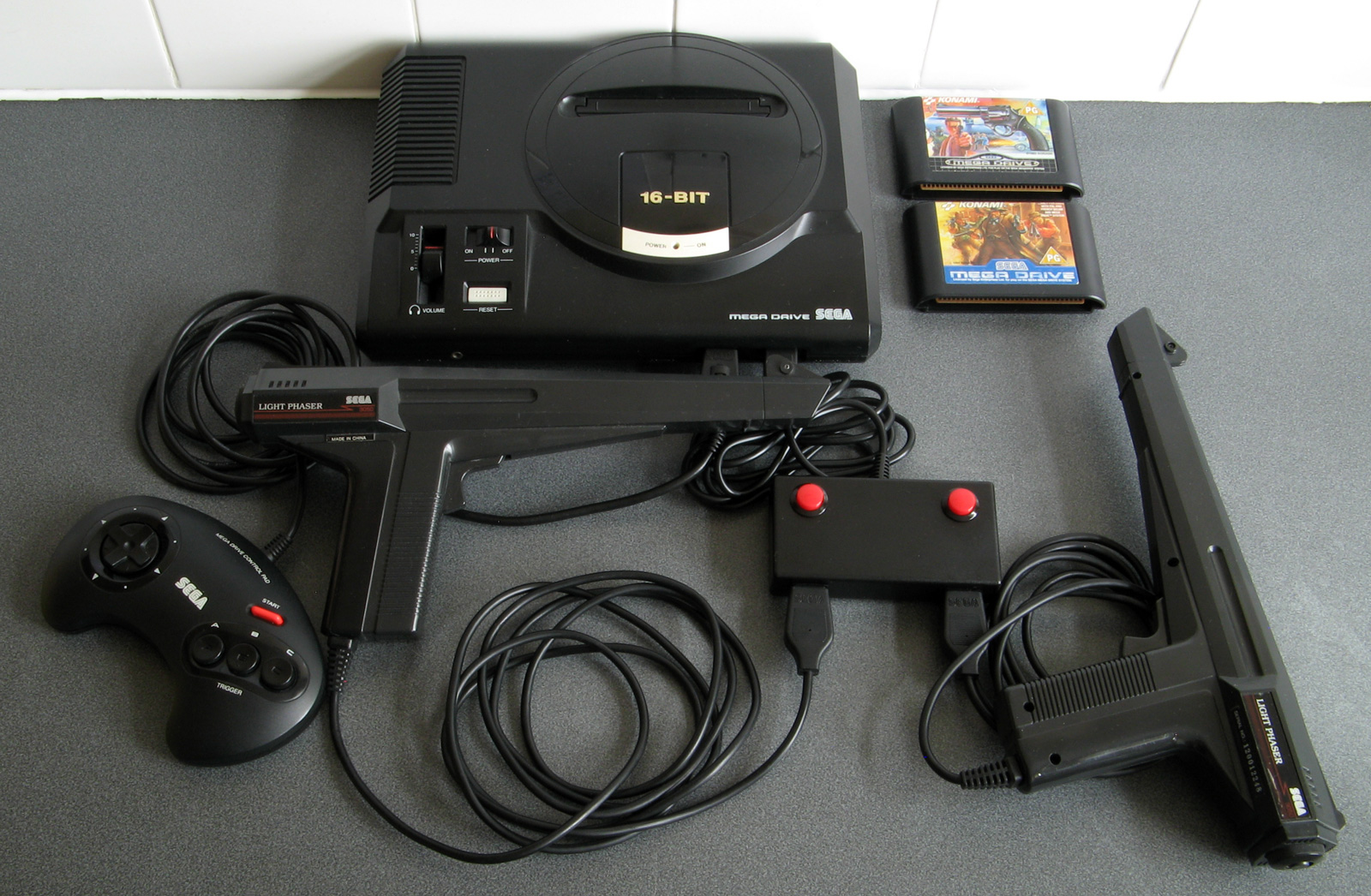
Whilst the epoxy was curing the final parts of the project could be assembled – a pair of start buttons had wires soldered to them with crimp connectors on the other end and a couple of rubber strips were cut to provide a bit of extra grip to the bottom of the adaptor. The various component parts of the project can be seen in the photo above.
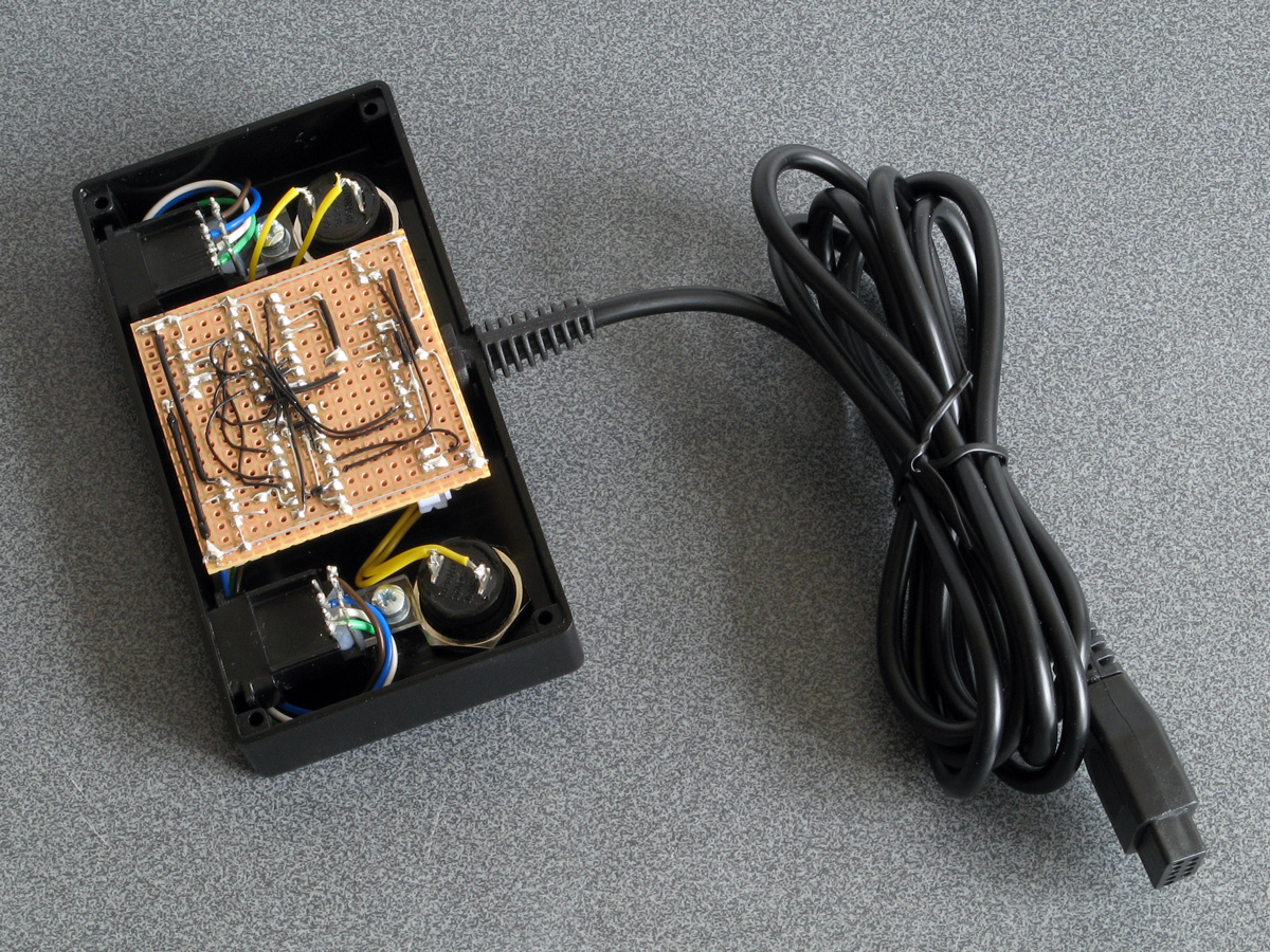
Everything does fit fairly neatly inside the enclosure, fortunately! After everything is assembled inside the bottom of the enclosure was screwed on and the rubber grip strips attached with double-sided sticky tape.
I still haven't been able to test this adaptor with any Mega CD games however it does work well in both Lethal Enforcers and Lethal Enforcers II: Gun Fighters on the stock Mega Drive so hopefully it will also work well in Mega CD games.
I'm pretty happy with how this project turned out. If you would like to assemble the adaptor yourself, you can find the schematic in the previous journal entry, and if you do build it I'd love to hear how you got on!
Adding some protective resistors to the Light Phaser to Mega Drive gun adaptors
Monday, 20th April 2020
Here's a quick update to the two Mega Drive light gun adaptor circuits, all to a few extra resistors in and around the adaptor and the console.
The real Sega Menacer receiver drives the TH line (used to indicate when the gun has seen light) directly from the output of a NOR gate with a 470Ω resistor in series. My circuit uses a transistor in the open-collector configuration with a 10KΩ resistor on the base input and a 1KΩ pull-up resistor, which is the same as the circuit used in the original Sega Light Phaser.
In a worst-case scenario the console could configure TH as an output, drive it high, and the Menacer adaptor could drive TH low at the same time. This would short the console's TH output to ground via the transistor, and might damage it (I'm not sure how these I/O ports are constructed internally). The TH output from a regular Sega Light Phaser would have the same problem, however that only pulses low briefly when it sees the light from the CRT whereas the TH output from the Menacer adaptor is latched and can stay low for a much longer time, increasing the risk. Resistors are cheap, so assuming the engineers at Sega know their hardware better than I do I thought it safer to add a 470Ω resistor on the TH output. This hasn't affected performance, as far as I can see. I also corrected the diagram to reference the BC548 as this is the transistor I tested with – the BC547 probably works too, however in the interest of accuracy I thought it best to stick with what I know works.
Sega Light Phaser to Sega Menacer adaptor
The Menacer circuit (as well as the original control pad) drives the DATA0~DATA3 lines directly so I haven't included any resistors there. I have, however, applied the same resistor changes to the Justifier adaptor:
Sega Light Phaser to Konami Justifier adaptor
As well as the 470Ω resistor on the TH input/output line I have added the 10KΩ resistors on the TL and TR input lines. I'm still not sure what these are for but as they are there in the Menacer adaptor and as Sega presumably know best I've included them here for completeness. As these are attached to inputs on the logic gates there should be very high impedance anyway, but it could be for protection in case the logic gates are improperly powered. What I do know is that the extra 10KΩ pull-ups on the TH inputs from the Light Phasers should protect against spurious TH outputs when either of the guns are unplugged.
I still haven't been able to test the circuit with any other games, but for now these two circuits seem to be holding up!
Simplifying the Light Phaser to Justifier adaptor to a two-chip solution
Saturday, 18th April 2020
In the previous post I mentioned I was dissatisfied with the optimisation of the Light Phaser to Justifier adaptor circuit. This was because I was using two quad two-input multiplexer chips (eight multiplexers total) but only using three multiplexers on each chip but also needed two inverter gates and so had to add a third chip to accommodate that requirement. It seemed like there must be a better solution, and after pondering this in the shower I think I found it.
One of the inverters is required for the transistor used to drive the TH line from the circuit. The TH line is bidirectional, and from our end of the circuit is either left floating (where it can rise high) or pulled directly to ground. To achieve this I was using an NPN transistor with the collector connected to TH, the emitter connected to ground and the base connected (via a resistor) to our logic signal. Unfortunately, such a transistor is switched on by a positive voltage and so a logic high at the input resulted in a logic low on TH, so to correct this an inverter was added.
A much simpler solution is to get rid of the inverter and transistor entirely and to replace it with a reverse-biased diode, replacing three components with one:
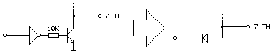
Current can only flow the diode if the voltage at the anode (right, connected to TH) is higher than the voltage at the cathode (left, connected to our logic signal). This means that if our logic signal is the same as the current state as TH then no current flows (and so we leave TH alone) and if our logic signal is high and TH is low then the diode is "backwards" and no current flows. The only way we can influence TH is if it is high and our logic signal is low, allowing current to flow through the diode, grounding TH – which is our desired outcome. One inverter is out of the way!
The other inverter is used to produce an inverted version of TH which is used when the console is retrieving the peripheral ID from the Justifier. We can use a multiplexer as an inverter by using the select pin as the input, tying the "0" input high and the "1" input low (that way when 0 is requested 1 is output and when 1 is requested 0 is output). The problem we have here is that all four multiplexers on a chip share a common selection pin, we need to invert TH, and neither of our two multiplexers is using TH as the select pin (one is using TR to select between the two guns and the other is using TL to globally enable or disable the guns).
The solution here is that we only need this inverted TH signal during the peripheral ID check which is carried out when the guns are globally disabled. When the guns are disabled we don't care about what the TR gun-selection multiplexer is doing, as whether the blue gun or pink gun is selected is irrelevant as the data never makes it to the console. We can therefore use the spare multiplexer on the TL-selected multiplexer chip to select between TR and TH, and use the output of this as the select pin into the multiplexer chip previously used to select between the two guns and use its spare multiplexer as the inverter.
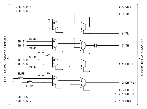
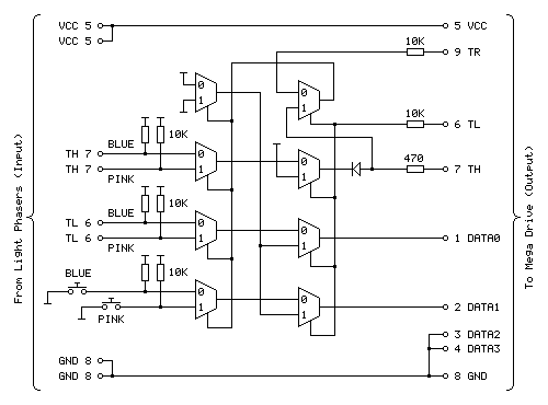
The revised circuit is shown above, the wiring is more complicated than the previous one however it takes advantage of all eight multiplexers on both chips and does away with the need to have an additional inverter logic chip and transistor driver circuit for TH.
The revised two-chip prototype is picture above, and has been tested successfully with Lethal Enforcers – performance doesn't seem to be any different from before, which seems to be a good sign!
Using Master System Light Phasers to play Konami Justifier games on the Mega Drive
Saturday, 18th April 2020
Following my adventures with building an adaptor that lets me use Sega Light Phaser guns in Sega Menacer games it seemed sensible to turn my attention to the other type of light gun for the Sega Mega Drive – the Konami Justifier.

These guns are unsurprisingly incompatible with the Sega Menacer and Sega Light Phaser and supported in even fewer games on the stock Mega Drive (only Lethal Enforcers and Lethal Enforcers II: Gun Fighters). However, these games are more in line with the type of light gun game that I like to play than what you'd find in the Menacer's library (even though the digitised sprites haven't aged particularly gracefully) and the guns are eye-wateringly expensive if you want to get a set of both for two-player games which makes the idea of a cheap adaptor to use the Master System's Light Phaser more appealing. And, of course, it's a fun challenge!
You may have noticed that the two guns in the photo at the top of the post are different colours, and unfortunately this is not purely cosmetic. The Justifier comes in distinct "player 1" and "player 2" variants, with the first gun plugging into the console and the second gun plugging into the bottom of the first gun using a modular connector in a daisy-chain configuration. This allowed Komani to sell console-specific blue player 1 guns and a generic pink player 2 gun that would work with the blue player 1 gun from any system. If you invited a friend over to play with you then you'd need to go out of your way to buy the specific player 2 gun (your friend's blue player 1 gun won't work), and as the blue gun was not sold separately you couldn't buy a game and "upgrade" to a light gun controller later, you'd need to buy one that came with a game and as a result both guns are now somewhat difficult to find and fairly expensive, especially the player 2 gun.
However, this arrangement should allow for a pretty neat solution where we can build a single adaptor that plugs into a controller port on the Mega Drive and provides two controller ports for the two Light Phaser guns rather than having to build two separator adaptors. Like the Menacer, the Justifier does have an extra button when compared to the Light Phaser however it's only one button this time (rather than three) and it's used as a Start button so both of these could be put on the adaptor unit itself between the two players.
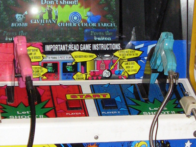
A Point Blank arcade machine with two Start buttons on the control panel between the two guns.
Without buying a pair of Justifier guns, how can it be studied so an adaptor can be built? In the case of the Menacer the receiver units can be bought cheaply and studied to figure out how they interface with the console and the patent document covers how it should work in high-level detail too. I have been unable to find such information for the Justifier. Fortunately Eke-Eke, the author of the Genesis Plus GX emulator, came to the rescue with the document gen_lightgun.pdf which goes into some detail about how the Justifier interfaces with the Mega Drive.
The key information to take into account here is that DATA0 is mapped to the trigger, DATA1 is mapped to the start button, TH is used for the light sensor, TR is used to select which of the two guns to query and TL is used as a general gun enable/disable line. As both guns share the same data lines for their triggers, start buttons and light sensors we can use multiplexers to select between the two guns.
The Mega Drive also needs to be able to detect when the Justifier is plugged in, and it does this by checking the state of the four DATA lines, once when TH is high and once when TH is low, then combining the bit values read in both states to form a single four-bit peripheral ID. The process was explained in more detail in an earlier post, however for the sake of simplicity to correctly return the device ID of %0001 we need to make sure that when TH is high all four data lines are low and when TH is low DATA2 and DATA3 should still be low and one or both of DATA0 and DATA1 should be high.
As DATA2 and DATA3 are always low and aren't used anywhere else they can just be tied low at all times and that should work. DATA0 and DATA1 should pass through the trigger/start button status (active low signals, so normally high) when the game is reading the button state but it looks like they should be forced low when TH is high. According to Eke-Eke's documentation: "I'm not sure why Justifier returns such values, maybe setting TH=1 will force input lines to 0".
My first attempt, therefore, was to use a NOR gate outputting to each of the two data lines with one input to each coming from the TH line and the other input coming from the inverted trigger/start button status. This way if TH was high both data lines would be forced low, otherwise it would output the inverted form of the input (and as the input to the NOR gate was already inverted, the final signal would be corrected – two wrongs do make a right in electronics!) This would not work if both trigger and start button were pressed, unfortunately, but maybe that wouldn't be a problem?
Happily, this worked in the menu for Lethal Enforcers, with the adaptor plugged in I was able to select the option to start a one- or two-player gun game! However, the game was completely unresponsive to the buttons. When writing an emulator you can make certain assumptions about how the hardware works, as long as the right values are in the right places when the software reads them. You also have the advantage of being privy to the internal state of the hardware that external devices might not be able to see! One important note in Eke-Eke's documentation is "this means the Justifier should return the following byte values when TH is set as output" – we can't directly tell whether a pin is set to an output or an input from outside the console, we can only see what its current signal level is. During normal gameplay TH is an active-low signal from the light gun's light sensor, and as a result TH is normally high which blocks the buttons from working. I had thought that maybe the game software would drive the TH pin low during its button-reading routine to allow the data to pass through but evidently the gun doesn't work this way.
Another issue is that whilst I can use a logic analyser to see what state the pins are in over a period of time, I can't tell at what point the console is reading those pins itself and making decisions based on what it sees. I could disassemble the game code to try to see how that's working, but I couldn't figure out any meaningful output from the disassembly tools I tried and couldn't find an appropriate debugging emulator so went back to trial and error.
The solution, I think, is in the TL pin being used to enable or disable the guns. I think that we should only mess around with forcing DATA0 and DATA1 high or low (based on the state of TH) when the guns are disabled, otherwise we let the button and light sensor state pass through. We can achieve this with two stages of multiplexers, one to select between the two guns (selected by TR) and another to globally enable/disable the guns (selected by TL). If we invert TH we can use this to drive the DATA0 and DATA1 lines when the guns are disabled, meaning that we also fix the problem where the gun wouldn't be detected if both buttons were held.
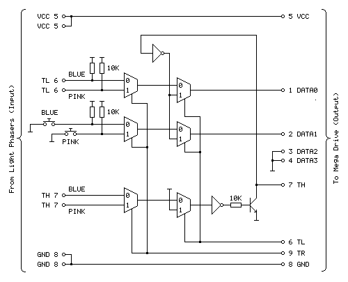
The above diagram shows the circuit I'm currently using to test with and it appears to work fairly well with Lethal Enforcers, being detected as a valid gun during startup and working in-game with both guns seemingly being handled correctly.
The first column of three multiplexers selects between the blue (player 1) and pink (player 2) gun inputs via the TR input. The top multiplexer handles the trigger (TL), the middle multiplexer handles the two Start buttons and the bottom multiplexer handles the light sensor inputs (TH). The second column of three multiplexers selects between the guns being enabled and guns being disabled via the TL input. When the guns are disabled (TL is high) DATA0 and DATA1 are driven by the inverse of TH to help provide the valid %0001 peripheral ID, allowing the adaptor to be detected as a Justifier.
The TH pin is a bit more challenging as it needs to be both an input and an output. At the moment when the guns are disabled it is driven high by tying the other input to the multiplexer high. The TH output is driven by a transistor; when the transistor is switched on it connects TH to ground (making it low) and when it is switched off it is left to float (normally floating high, but otherwise under the control of the console). As the transistor is switched on by a positive voltage this effectively acts as an inverter, hence the signal from the multiplexer to the transistor also needs to be inverted.
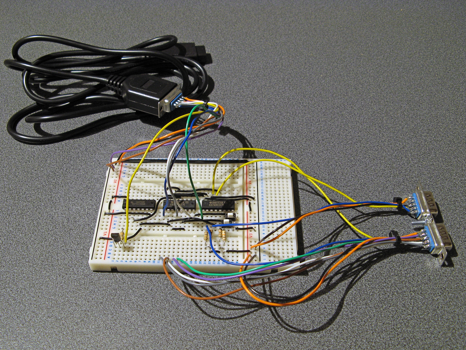
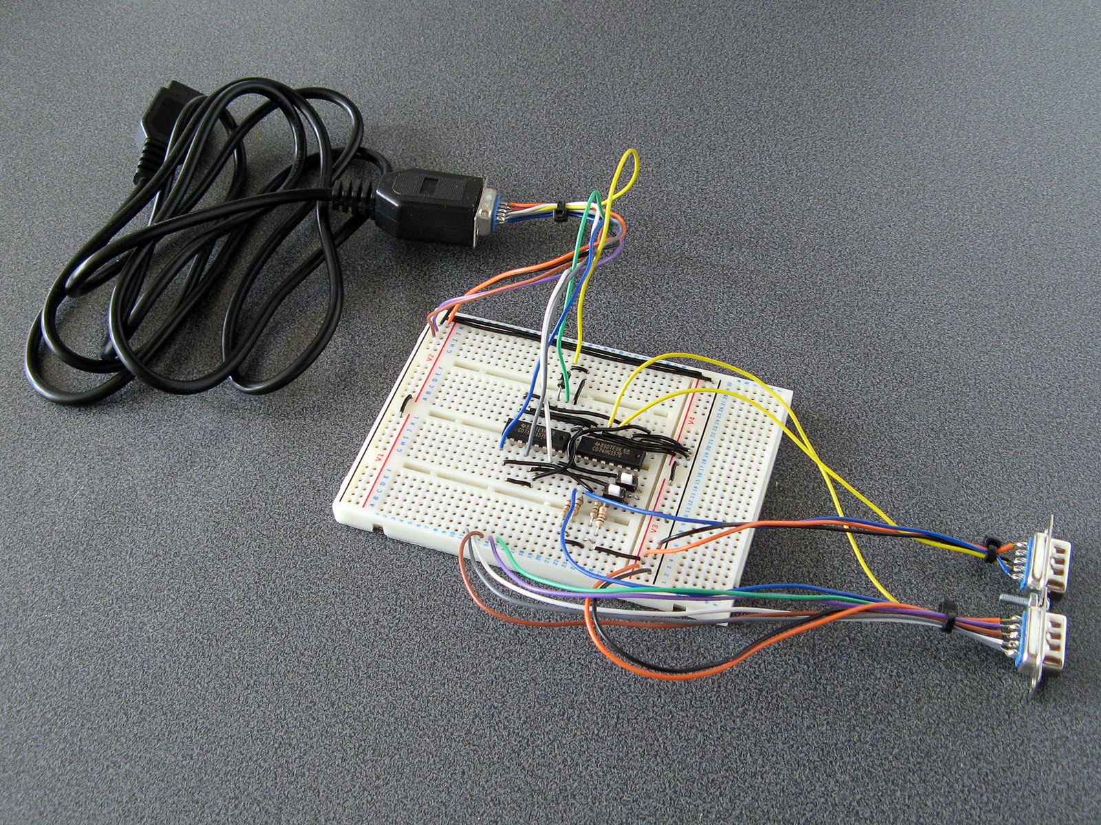
The prototype adaptor assembled on a solderless breadboard.
I'm not entirely happy with the way the circuit has been implemented, in particular the use of two multiplexer chips where only three of the four multiplexers are used and the need for an additional chip for the inverter gates. Multiplexer chips normally have a global enable/disable pin in addition to their data selector, which makes me wonder if such a pin could be useful. The 74HCT157 chips I'm using drive the outputs low when disabled which would not be very useful in this particular use case, however other chips are available that make the outputs high-impedence when disabled which may be more useful and allow for a circuit design that uses fewer parts.
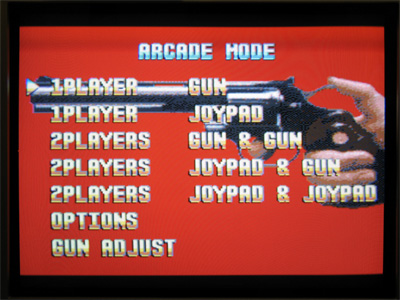
There is also a slight issue of reliability and accuracy. When playing the game shots are generally fairly accurate and always register however they sometimes are offset horizontally. Eke-Eke's document points out that Lethal Enforcers does not use the console's horizontal counter latch so the inaccuracy may be a software issue – interestingly it seems Lethal Enforcers II does use the horizontal counter latch so when I can test with this cartridge it will be interesting to see whether accuracy is affected. More weirdly, the game does provide a "gun adjust" menu option where you can calibrate the game to compensate for any horizontal or vertical offset in the gun hardware however this does not seem to detect all shots and sometimes the accuracy is miles out! This also seems to be affected quite heavily by proximity to the screen, normally bringing the gun closer to the screen yields more accurate results however here it seems to make things worse. I'm not sure why this is and will continue to test the circuit to see if performance can be improved.
The completed Light Phaser to Menacer adaptor
Friday, 10th April 2020
In the last post I was having difficulty with the overall logic for handling the light sensor signal from the Sega Light Phaser and passing that along to the Mega Drive as if it was coming from the Menacer receiver. This involves latching the signal (instead of passing it along directly) and allowing the console to reset it once handled via the TR line. The signal needs to be delayed as well to simulate the delay from the overhead of the Menacer's wireless communications; without this delay the aiming is offset to the left. The signal is also gated using the TL line; I'm not entirely sure why this is done (some form of external interrupt inhibition?) but it's part of the original receiver so I thought it best to implement this for the sake of compatibility.
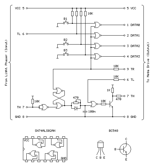
My main problem was that the CMOS NOR chip I had to hand was not triggering reliably with the signal from the light gun and the RC circuit used to delay that signal; I'd swapped it for a TTL NAND chip which then did work however the logic inputs to the latch were inverted (a simple NOR latch has active-high inputs and a simple NAND latch has active-low inputs) and to fix this would have required a lot of additional logic gates. I ordered an SN74ALS02AN TTL NOR chip and found that this worked very well, so have settled on the following circuit:
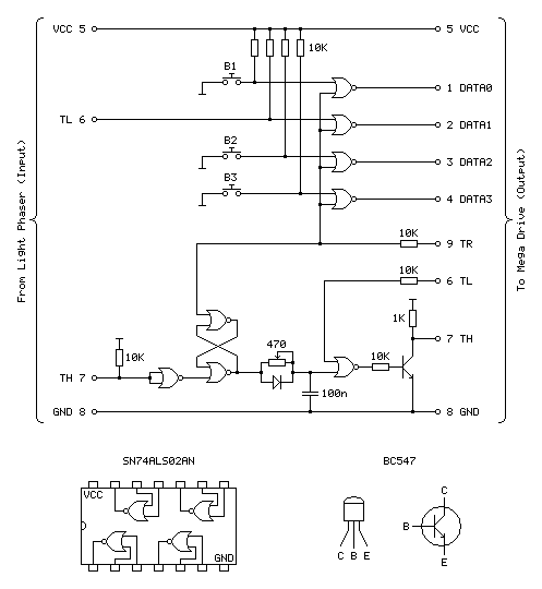
Update (20/04/2020): Please see this post for an updated diagram with a protective 470Ω resistor on the TH output
The four NOR gates towards the top of the circuit diagram are used to gate and invert the inputs from the four input buttons (one main trigger on the Light Phaser and three secondary function buttons on the adaptor itself). This is unchanged from the previous circuit and still works well.
The most important aspect of the circuit at the bottom of the diagram between the two TH pins is the latch made of two crossed-over NOR gates with the output from one going to the input of the other and vice-versa. The two inputs to this latch are normally low (TR from the console is driven directly and normally low, TH from the Light Phaser is normally high but inverted by a NOR gate with its legs tied together). When the reset pin TR goes high the output of the top gate must go low, as a NOR gate will always output low if either (or both) of its inputs are high:
| Inputs | Output | |
|---|---|---|
| A | B | Q = A+B |
| 0 | 0 | 1 |
| 0 | 1 | 0 |
| 1 | 0 | 0 |
| 1 | 1 | 0 |
If we assume that the other input to the lower NOR gate is also in its default low state then the two low inputs will result in a high output. This high input travels back to the top NOR gate's other input. This means that even when the TR pin goes back low again there is still a high input on that top NOR gate and so it maintains its low output.
When the Light Phaser sees light its TH output goes low, the NOR gate with its legs tied together inverts this to go high and the bottom input to the lower NOR gate in the latch goes high. This makes its output go low, which travels to the top NOR gate, making both inputs low (assuming TR is still low) and making the top NOR gate output a high which comes back down to the lower NOR gate so that even when the Light Phaser stops seeing light and the other input to the bottom NOR goes back to low there is still a high on the other pin, keeping the overall output low.
Effectively, what this means is that when the Light Phaser sees light the output of the latch goes low, and to return this back to a high the console needs to pulse the TR pin high.
The output of the latch goes to a delay circuit consisting of a resistor, capacitor and diode. This delay is required because the real Menacer introduces a delay between when it sees light and when it triggers the console's TH pin, and games are programmed to compensate for this. Without replicating this delay the aim is offset considerably to the left.
The logic gates are digital devices however still adhere to analogue rules and will treat certain voltages as high or low digital signals when they pass a certain threshold. The delay is implemented by slowing the rise or fall of the logic signal by charging a capacitor via a resistor, so whilst the logic signal at the output of the latch changes very quickly it will take the capacitor a while to charge or discharge via that resistor to a voltage level that is interpreted as a change of state by the following logic gate. The diode is there because we want the signal to be delayed when the gun sees light (when the logic level goes from high to low) but want it to change quickly when the latch is reset (going from low back to high again). When going from low to high there is a higher voltage to the left of the diode than there is across the capacitor to its right and so current can flow quickly through the diode, bypassing the slow resistor and charging up the capacitor quickly. When going from high to low the current can't flow backwards through the diode and so the capacitor has to discharge slowly through the resistor, providing the desired delay.
After this delay comes another NOR gate with its other input coming from the console's TL pin. I'm not entirely sure what this is for, as mentioned above, but it does at least allow us to buffer the signal from the RC delay circuit. The real receiver circuit then uses a final NOR gate with its inputs tied together to invert the latched signal before passing it to the console via a 470Ω resistor, but as I am already using an extra NOR gate to invert the input from the Light Phaser and have therefore used all four gates on one chip I instead use a transistor with a 1K pullup to invert the signal. The Light Phaser uses such a transistor circuit with the same 1K pullup resistor on its TH output so I thought it safe to use it here as it would be electrically compatible. The real receiver also includes 10K series resistors on its inputs from the TR and TL lines – I'm not entirely sure why but in case there was a good reason I thought I should use them here also!
With the circuit appearing to work well I thought it was time to put it in an enclosure. I found a box that was a comfortable size to hold in one hand – it's about the same overall size of a Master System control pad other than being quite a bit fatter. This allowed me to put the three push buttons down the side of the box so they can all be pressed easily when gripping the box in one hand. The lid of the box has a lip that would interefere with the ability to tighten the nuts for the buttons and so I cut a small piece of acrylic that is slightly thicker than the lip and short enough that the box can be closed with it in place.
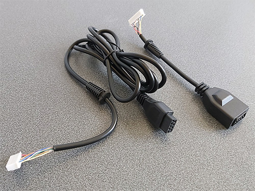
Of course, we need something to plug the Light Phaser into and a cable to plug the adaptor into the console with. A good source for these connectors is an inexpensive extension cable, so I bought one and cut it in two so I could use it for this project. After cutting the cable in two I installed strain reliefs and crimp connectors, and definitely remember to do that in that order! Interestingly I've bought a few of these cables recently from different suppliers (and with different moulding designs for the console plug and controller socket) and they've always been about half the length advertised but sold in packs of two.
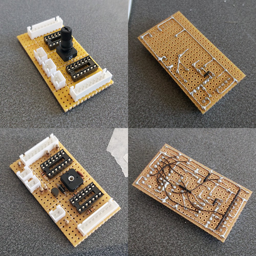
I normally use pad board to solder my final circuits together. I start by roughly placing the components on the board where I think they should end up going, and when I've got the main parts in place I flip the board over and start soldering them down, using bare pieces of wire to make connections between components. I lay the bare pieces of wire as straight as possible and try to avoid crossing them over; where necessary I'll add a piece of insulation to a wire where it needs to cross another. Once as much of the board is placed in that fashion I'll solder thin wires between the points that can't have direct connections. It may not be the prettiest job (and making corrections afterwards is a bit of a pain) but it's worked well for me and I've found it allows for more compact layouts than stripboard.
Some crimp connectors were then added to the three push buttons and the whole circuit was installed in the box. Before the lid was screwed down the delay to correct the horizontal aim was calibrated using the 470Ω variable resistor. To adjust it the variable resistor was first set to its smallest resistance value and the tip of the light gun was touched to the centre of the screen. The aiming reticle is quite far to the left by default so the resistance of the variable resistor was then gradually increased to move the aiming reticle in the game right until it sits under the tip of the gun. The aim was then checked at the extreme left and right sides of the screen and if there were any dead zones the variable resistor was adjusted to move the aiming reticle away from the edge of the screen until it had a good range of motion across the entire width of the screen.
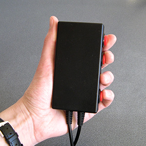
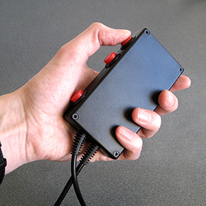
The two different grip styles for the adaptor buttons
The adaptor can be gripped in two different ways – in the regular position you have direct access to all three extra buttons with your fingers, and in the reversed position you have access to a single button at a time with your thumb. None of the games I've played on the Mega Drive use more than two extra buttons (and usually one of those is the bottom "Pause" button) but it's always good to have options!
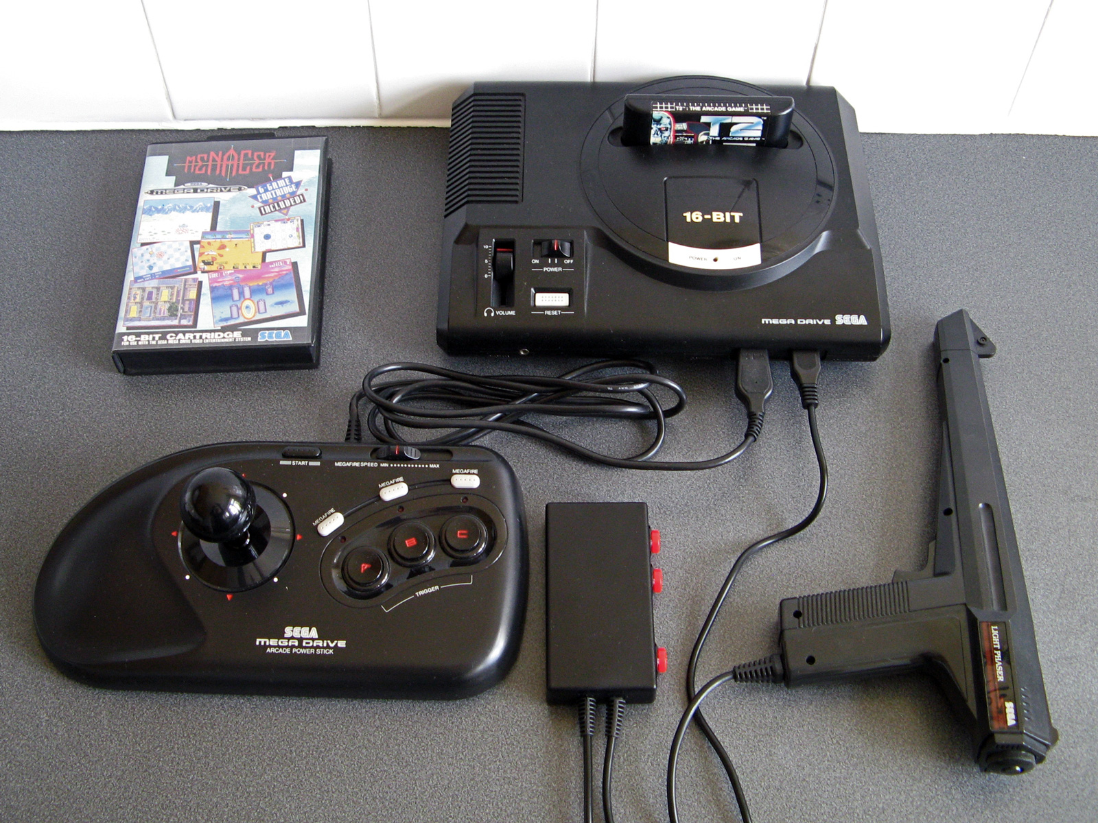
I have tested the adaptor with the three Mega Drive games that support the Menacer — the six-in-one pack-in cartridge, T2: The Arcade Game and Body Count and am happy to report that it works with all three. I am not going to be able to test it with any Mega CD games as I do not have a Mega CD or a compatible flash cartridge, I'm afraid to say, but hopefully it will work just as well with those games.
The red and black theme was chosen to match the other accessories and I think it fits in rather well, even if it is a bit boxy-looking. If you are reading this and build the circuit yourself I'd love to hear how you get on!