Arcs, segments and sectors in BBC BASIC for the Sega Master System
Tuesday, 12th October 2021
More musing on tape phases
I bought a few more Acorn-format BBC BASIC cassettes to test my adaptation of BBC BASIC to the Sega Master System with, and have found a few interesting oddities since my last post. In that post I made the assertion that the phase of the recorded signals on the tapes is at 180°, i.e. each wave cycle goes negative before it goes positive (whereas a 0° phase would go positive before it goes negative). This matched the documentation I'd read, the output of tools like PlayUEF and my own tests with commercially-recorded tapes. With these new tapes I've found things are not quite so straightforward, though:
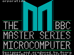
- The "Welcome" tape for the BBC Master Series is recorded at 0°. OK, maybe that's a BBC Master weirdness?
- One copy of the "Welcome" tape for the BBC Micro is recorded at the usual 180°, hooray, we're back to normal!
- Another copy of the "Welcome" tape for the BBC Micro is recorded at 0°. It's also a different colour, but otherwise has identical programs on it, maybe the difference comes from different duplication plants?
- Side A of Acornsoft's "Graphs and Charts" is recorded at 180°, Side B of the same tape is recorded at 0°. Flipping the tape flips the phase, I give up!
I am able to load the programs by changing the "phase" switch on my cassette recorder to "reverse", but not all cassette recorders have such a switch. There is a jumper setting in the tape interface circuit that the cassette loader software can check to control whether it starts timing the length of wave cycles on a falling (180°, default) or rising (0°) edge and so it can compensate for the reversed phase, but I'd rather see if I can find a way to automatically detect the phase and properly recover data without needing to rewind the tape, push a switch or type in a command, then trying again.
A "1" bit is represented by two 2400Hz cycles and a "0" bit by a single 1200Hz cycle. Each byte has at least one "1" bit before it and always starts with a "0" start bit. In theory, then, a "0" bit with the correct phase should be represented by a wave cycle that's 2× the length of a preceding 2400Hz cycle, but if the phase is incorrect it'll only be 1.5× the length. At the moment the threshold to detect the difference between a 2400Hz and 1200Hz cycle is placed at 1.5×, maybe for the start bit it needs to be at 1.3× to detect the "0" bit instead, and if after that the wave is over 1.6× it's treated as a "normal" 180° tape and loaded as normal, but if it's between 1.3× and 1.6× it's treated as a "reverse" 0° tape and an extra rising edge is checked for before loading the tape with reverse phase.
I'm not sure if that'll work and my quick initial tests didn't work very reliably so I'll need to do a bit more experimentation I think. I did encounter another oddity with formats beyond the reversed phase, though, and that's with Acornsoft's "Graphs and Charts". The tokenised BASIC programs on the tape would crash the loader or generate "Bad program" errors, and when I copied the tape to my PC and looked at the files there I could see that BBC BASIC for Windows refused to open them too. The problem is that instead of the usual <CR><FF> terminator on each program, they all end with <CR><80> instead. My loader tries to convert Acorn BBC BASIC format programs to the Z80 BBC BASIC format automatically during the load, but if it misses the terminator when stepping through the program it will either see the line as being zero bytes long (due to memory being cleared to 0) and loop infinitely when attempting to jump to the next line, or read a line length from uninitialised memory that causes it to advance to a line that doesn't start with the appropriate byte and so assume the program is not in Acorn format, skipping the conversion process and leaving a "Bad" program in memory.
I made my loader more robust by appending a suitable dummy terminator to the loaded program; if it already was a valid program with a proper terminator then it makes no difference, but it otherwise prevents the convertor from dropping off the end of the program and allows me to load the programs from the "Graphs and Charts" tape.
Drawing arcs, segments and sectors in BBC BASIC


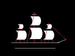
I hadn't implemented all of the PLOTting routines that BBC BASIC can provide for drawing graphics on the screen, and a few of the programs on the BBC Master Series "Welcome" tape take advantage of the more advanced routines to draw circular arcs, segments and sectors. Attempting to run these programs produced results like the picture of the clown above with several parts of its face missing.
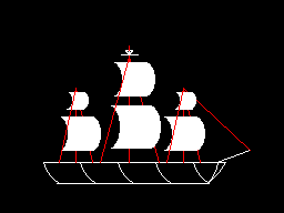
I had been putting this off as I hadn't been able to think of a good way to implement drawing these shapes. After a bit more research online I came across a paper by C. Bond entitled An Incremental Method for Drawing Circular Arcs Using Properties of Oriented Lines which turned out to be ideal.
The linked paper does a very good job of describing the technique so I would recommend reading it, but crucially it provides a solution that can be implemented easily in Z80 assembly with a few integer multiplications and additions. I was able to incorporate this into the existing circle tracing and filling code without too much effort, just an extra step in the "plot pixel" or "fill horizontal span" routines to clip against the lines that bound the arc, segment or sector.


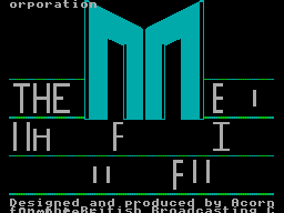
As you can no doubt see from the "Welcome" screen at the end there are still parts missing from the final image. This is because the program only draws each required letter once and then uses the block copying PLOT routines to duplicate the letter if it's needed again instead of rendering it again from scratch – hence the second "B" from "BBC" is missing, and "MASTER" becomes "MAS R" as the program is expecting to copy the "T" and "E" from "THE" in the line above.
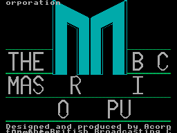
Disabling this optimisation within the BASIC program and forcing each letter to be drawn instead of copied does improve the results, though it still doesn't entirely fit on the screen due to the much lower resolution!
Tape cycle frequencies and phases, plus VDrive3 support for BBC BASIC on the Sega Master System
Wednesday, 6th October 2021
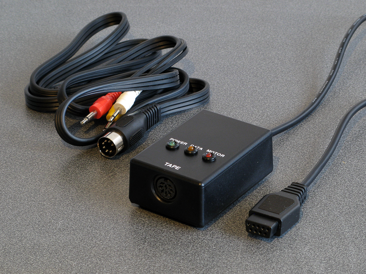
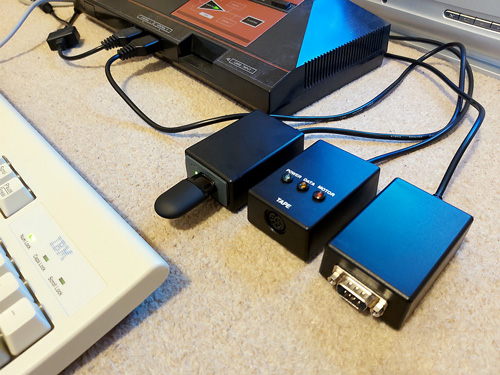
I have now moved the tape interface circuit described in the previous entry from its breadboard prototype to a neat enclosure where I am happy to report it mostly works as well as it did before.
I have spotted two issues, though. The first affects my small cassette recorder but not the large one, and is related to reading files from tape via the file IO routines (such as OPENIN then BGET# to retrieve a single byte, not from LOAD). Files are stored on tape in 256 byte blocks, and when the file is opened a whole 256 byte block is read from the tape and copied to the Master System's RAM. When the BASIC program requests a byte from the tape it is read from this local copy of the block instead, and when the read pointer reaches the end of the 256 byte block the next block is fetched from the tape and the local copy updated with this new data. The motor control comes in handy here, with the file system library stopping and starting the tape playback as desired.
The problem I was having was that the first block would read fine, but when the time came to read the second block the tape started playing but the file system library never seemed to be able to detect any data – it would just work its way along to the end of the tape, never displaying any errors, but never reading any meaningful data either.
The issue ended up being some code I'd added somewhat recently to automatically calibrate the threshold between a 1200Hz ("zero" bit) and a 2400Hz ("one" bit) tone. The code reads bits by counting the length of each wave cycle and comparing this to a threshold value - if it's longer, it's the 1200Hz "zero" bit tone, if it's shorter, it's the 2400Hz "one" bit tone. Before and after each file, and between each block, is a section of 2400Hz "carrier" tone. By detecting a large number of wave cycles that were all around the same length (say, within four length units of each other) you could assume that you were receiving the 2400Hz carrier tone and use that to calculate a suitable threshold for loading in data later.
The main bug was that I was comparing the length of the wave cycle just received with the length of the previous wave cycle rather than the length of the first wave cycle. This becomes a problem when you start a tape that was paused in the middle of a carrier tone (e.g. between blocks) as the tape will take some time to come up to speed, during which time the period of each wave cycle will gradually decrease. As the reference length we're checking the current wave length against is changing over time it means we end up compensating for the tape's speed increasing and so end up accepting the slower (longer) wave cycle lengths as part of the calculation of the threshold between "zero" and "one" bit wave cycle lengths.
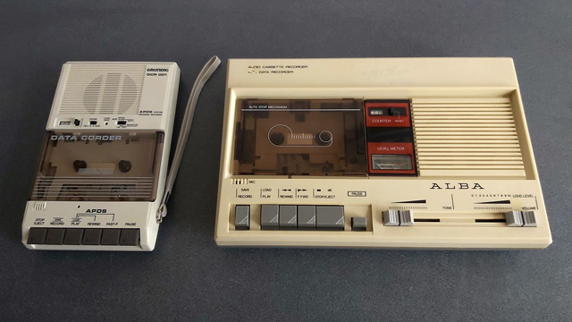
As the wave cycle length threshold is now longer than it should be, all incoming wave cycles get interpreted as short ones and so it looks like we're just getting a stream of "one" bits - which looks like the carrier, so the code never starts trying to decode any blocks. My larger tape recorder comes up to speed much more quickly than the small one, or at least doesn't audibly ramp up in speed, and so isn't affected by this problem.
Fortunately the fix is very easy, just check the length of wave cycles against the first wave received rather than the previous one. This way if the timings drift over time (as they would during the period that the tape is coming up to speed) then they'll eventually go out of the permitted range. Changing this fixed the issue.
You may wonder why I'm calculating the threshold at runtime instead of just using a hard-coded value if the expected frequencies are a fixed 1200Hz and 2400Hz. My main intention was to be able to handle tapes that were running at the wrong speed due to a miscalibrated cassette recorder, but this does also open up the possibility to load from tapes at higher rates. Without any further adjustment my code can already load from audio generated at 2320 baud, i.e. with the two frequencies at 2320Hz and 4640Hz, without any further adjustment. This is a slightly annoying figure as 2400 baud would be the obvious target (being double the intended rate!) but at this speed the current code fails to latch on to the signal so I slowed the "tape" speed down until I found a value that worked. It's perhaps worth mentioning that the audio in this case was coming from PlayUEF running on my phone rather than an analogue cassette tape with the BAUD (or LOW) parameter used to adjust the speed, I'm not sure that a 93% boost in loading speed would be achievable from a tape!
I mentioned above that there were two issues. The slow speed-up issue affected the small cassette recorder, but the large cassette recorder had a new issue that only became apparerent after moving the circuit to its final enclosure. The Master System should be able to start and stop the cassette remotely, handled by a reed relay that is then plugged into the cassette recorder's "remote" socket. The Master System was able to start both tape recorders without any issues, but was unable to stop the large one – the "motor" status light would switch off, but the tape would continue playing. Tapping the relay sharply would be the only way to get it to switch off.
I tried plugging in a 2.5mm TS plug into the side of the large tape recorder and used the very scientific approach of shorting its connections with a screwdriver to simulate the relay switching "on" and was surprised to see quite large sparks. I measured the DC current through the remote control switch when the cassette was running and it was only around 70mA at its highest – well below the 1A rating of the relay – however I reckon there is a very large inrush current when the motor kicks in that is sufficient to weld the reed switch contacts together, causing it to get stuck.
Why didn't this affect the circuit on the breadboard? In that setup I was using a 3.5mm TS extension cable connected to a 3.5mm male-to-male adaptor cable which was then connected to a 3.5mm to a 2.5mm adaptor cable. My assumption is that all of the extra contact resistances were helping to limit the inrush current, preventing the contacts from welding together.
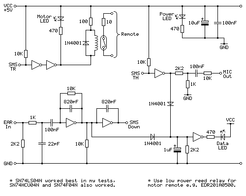
It's very likely not the best sort of snubber circuit for this application but for the time being I've put a 10Ω resistor in series with the relay contacts, which limits the inrush current enough for the relay not to get stuck:
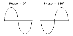
One matter that I've also been testing is the phase of the audio signal. As far as I can tell Acorn's tape format assumes a 180° phase; that is to say that each wave cycle starts at 180° and runs to 180°+360°=540° for a complete cycle rather than starting at 0° and running to 360°. The result of this is that instead of the signal starting at an amplitude of 0, then going positive before negative (as you'd expect for a typical sine wave) the signal goes negative first:
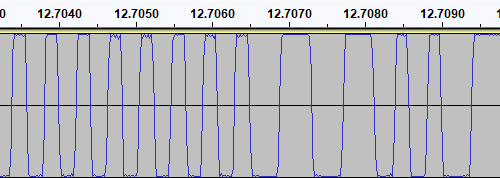
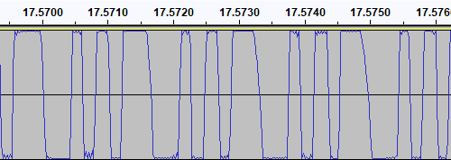
I have confirmed this by looking at the output of tools like PlayUEF as well as looking at the signals coming directly off commercially pre-recorded tapes with BBC Micro software on them, after first confirming that my sound card doesn't invert the signal by briefly connecting its input to a positive DC power supply and seeing that the received signal goes positive when that happens. Here's an example of a commercially-released tape, where you can see that after the high-frequency cycles in the first longer wave (a "zero" bit, acting as the start bit, starting at around 12.7065) starts low then goes high:
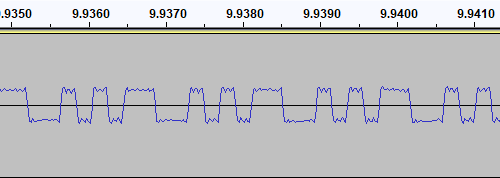
I then generated a test tone that alternates between 0 and 1 bits, i.e. one complete 1200Hz cycle then two complete 2400Hz cycles with the appropriate 180° phase:
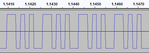
This pattern should make it easy to spot the phase of recordings. I first tried running the test tone straight back into my PC to ensure that the phase was not being reversed by the PC, and got the same signal back in compared to to what I played out, as you'd expect. I then tried recording the signal to tape with my Grundig recorder, and found something interesting when playing it back:
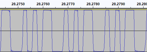
The phase there is very clearly reversed – the signal I played into the tape recorder goes low before it goes high, whereas the signal I've recovered goes high before it goes low. I repeated the test with the Alba tape recorder:
This shows the same thing – the phase on the tape is at 0° even though the test signal was at 180°. I also have a Sony digital voice recorder (an ICD-BX140) that I've been using as well as a tape recorder, so I tried the test with that too:
Apart from the much lower recording level this once again shows the same thing – the signal phase is inverted when recorded.
I had previously encountered an issue where I had tried to make a tape from a UEF image by playing the audio generated by PlayUEF into a tape recorder. Attempting to load the data directly from PlayUEF worked fine, but the tape recording of the same signal wouldn't load. My Grundig tape recorder has a phase reversal switch, and setting it to "reverse" would allow me to load the tape created by recording the output of PlayUEF. However, in that reverse setting, I lost the ability to load from my commercially-recorded tapes. I think the above tests indicate why this is the case – the recorders all invert the signal when creating the tape recording. I find it particularly interesting that the Sony digital voice recorder does the same thing!
I did check to see if the phase switch on the Grundig tape recorder had any influence on the recording, but it doesn't – whether it's set to "normal" or "reverse" the recording to tape still ends up inverted. The phase switch only appears to affect playback.
PlayUEF does have an option to set the output phase to 0° instead of its default 180°. By doing that and recording its output to tape I was able to load the programs directly from either of my tape recorders.
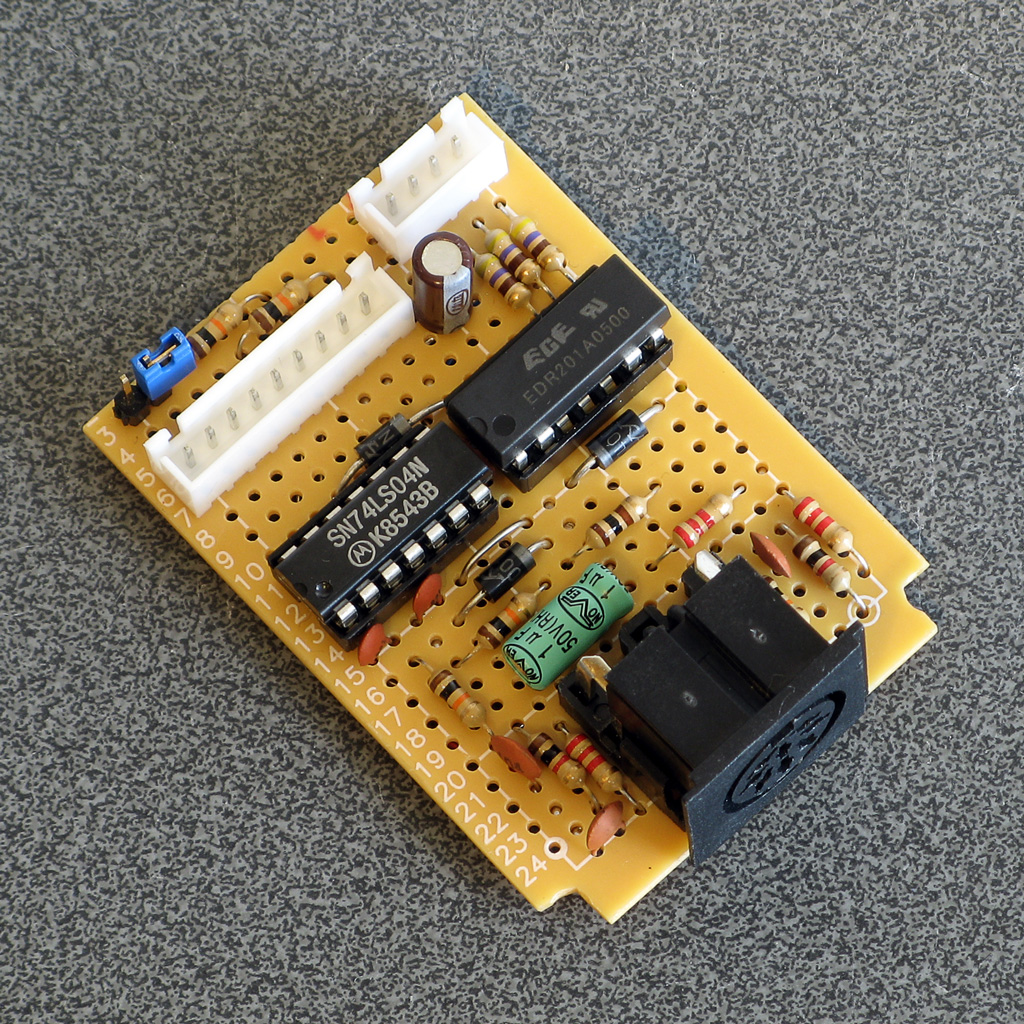
Of course, it would be nice if the loader was able to handle either phase, and in practice I've found it does sometimes handle the "incorrect" phase quite well but it does seem to be more a lot more error prone – some programs load without any problem, others report problems with some blocks and others fail to be detected at all! I think I'll see if there's a way to reliably detect the phase and switch to the appropriate handler, but for the time being I've added a crude workaround – pulling pin 1 of the controller port (the d-pad "Up" input) to ground tells the loader to assume the phase is inverted. As I hope this won't be necessary in future I've left this as a jumper in my current tape interface circuit (visible below in the top left corner) rather than add a switch!
A lot of the work has been focused on the tape loader, but tapes are not the most practical storage media these days. Finding a working tape recorder is a challenge in its own right, and a lot of the old tapes are tricky to work with as they've become sticky with age. In an attempt to be a bit more modern I've started integrating support for the VDrive3 to BBC BASIC. This is an inexpensive module that lets you access files on a USB mass storage device via simple commands sent over a serial interface. I'd previously used the VMusic2 device in another project and that uses the same firmware commands so I already had a little experience with it (the VMusic is pretty much a VDrive with an MP3 decoder bolted on top). I already had some serial routines written so it was a reasonably easy job to plumb in some code to handle LOADing and SAVEing programs, and from a hardware perspective all you need is a cable to connect the module directly to the Master System's controller port – the VDrive3 uses 3.3V signalling levels but its I/O lines are 5V tolerant.
One notable advantage of the VDrive3 over the tape interface is that it allows for proper random-access of files rather than just sequential access. I've been working on implementing all of the required BASIC statements to support this (OPENIN, OPENOUT, OPENUP, BGET#, BPUT#, PTR#, EXT#, EOF#, CLOSE# etc). For a bit of fun I wrote a BASIC program that loads an image file from disk (or tape) and displays it on screen. I needed to add user-defined character support to the new reduced-resolution MODE 2 to handle this (something that was not implemented before due to a lack of VRAM) but with that in place it's working pretty well.
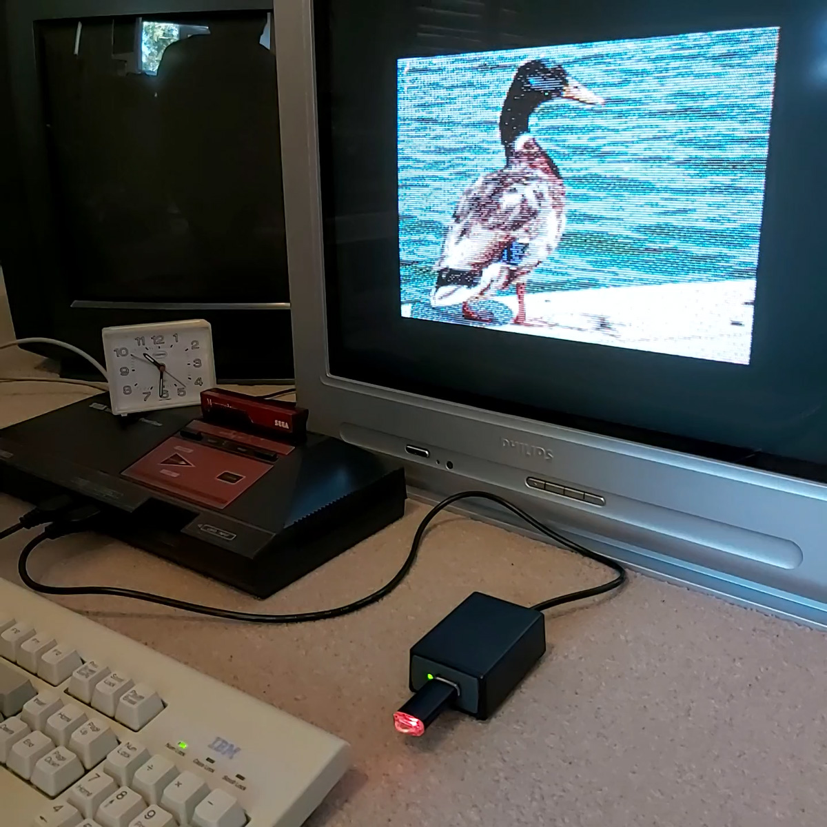
It's not fast, taking 2m45s to load from from tape and 1m19s from a USB flash drive, but it's a fun diversion!