Combining a Z80 and an ATmega644P to boot CP/M
Monday, 14th June 2010
I've been working on a new Z80 computer over the last few days. I would say that I had been working on the existing Z80 computer were it not for the fact that this a completely new design.
The previous computer had two 32KB RAM chips to provide a total of 64KB RAM. To run a user program you need to get it into RAM somehow, so I also included a 128KB ROM chip which occupied the lower 16KB of the Z80's address space to provide the fixed operating system that could be used to load programs. By adding memory banking hardware I could select one of eight 16KB pages of ROM. The next 16KB was one of two banks of RAM from one RAM chip, and the final 32KB was mapped directly to the other RAM chip.
This is all fairly complicated, and not very flexible. Programs written for CP/M tend to be loaded into memory starting at address $0100, which is impossible with my old design as that section of memory is taken up by ROM.
Giving another device access to the buses
The Z80 accesses memory and other hardware devices using three buses; an eight-bit data bus which shuttles bytes of data between the various chips, a sixteen-bit address bus which addresses a location in memory or a particular I/O device, and a control bus which contains numerous lines that specify the type of operation (for example, if /MREQ and /WR go low together it indicates that a byte is being written to memory, or if /IORQ and /RD go low together it indicates that a byte is being read from an I/O device).
There is also a pin named /BUSREQ that can be used to request access to these buses. The Z80 will periodically check this pin and if it is held low it will put the data, address and control buses into a high-impedance state and drive /BUSACK low to acknowledge this. This effectively removes the Z80 from the circuit, and another device can now drive the buses.
;if(img.style.backgroundImage){img.style.backgroundImage='url('+img.src+')';img.src=imgs[img.src.indexOf(imgs[1])<0?1:2]}else{img.style.backgroundImage='url('+img.src+')';img.src=imgs[2];};void(0);)
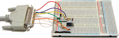
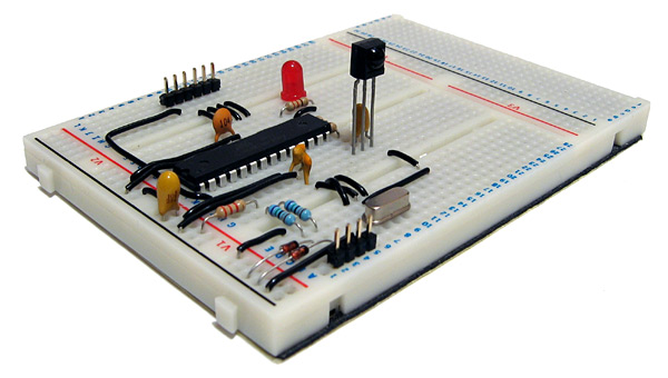
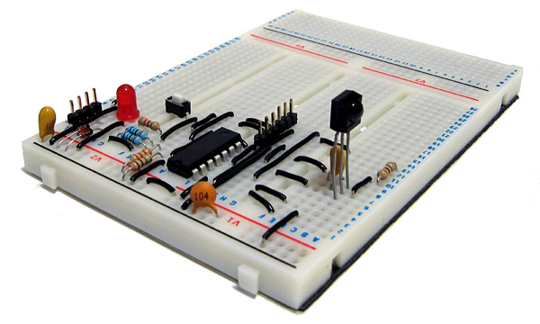
This is the feature which I have based the new design around — the current prototype is pictured above. It features a Z80 and 128KB of SRAM (only 64KB is currently addressable) on the upper board. On the lower board is an ATmega644P microcontroller, which is used to start the computer.
When the circuit is reset, the ATmega644P requests access to the buses from the Z80. When access has been granted, it proceeds to copy the CP/M BIOS from the 512KB flash memory IC to a specific location in RAM (currently $F200). It then writes the Z80 jump instruction jp $F200 to the start of memory, returns control of the buses to the Z80 and pulses its /RESET pin. The CP/M BIOS then runs directly on the Z80.
As the ATmega644P doesn't have enough pins to drive all of the buses directly, I've added sixteen GPIO pins by using two MCP23S08 8-bit I/O expander chips. These are used to drive or sample the Z80 address bus; the data and control buses are driven or sampled directly by the GPIO ports on the ATmega644P.
Using a slow to respond microcontroller for I/O
The Z80 is most useful if it can talk to the outside world somehow, which is usually achieved by reading from or writing to I/O devices. In my previous design I built these out of latches and lots of glue logic. As I've added a powerful microcontroller to the computer which features a number of useful on-board peripherals, it would seem sensible to use that instead.
One problem with this idea is that the Z80 expects to read or write to an I/O device in a mere four clock cycles. The AVR has a delay between an interrupt occurring (such as a pin state changing) and executing interrupt service routine of at least five clock cycles. Even though the AVR is running at twice the clock speed of the Z80 this still doesn't provide much time to sample the address bus and perform some useful action before returning a value to the Z80. Fortunately, the Z80 has another useful pin, /WAIT, specifically to address this concern. By pulling this pin low the Z80 can be stalled, allowing the I/O device plenty of time to respond. I have included a 7474 D-type flip-flop as an SR latch to control the /WAIT pin. When the Z80's /IORQ pin goes low the flip-flop is reset, which pulls the /WAIT pin low. When the AVR notices that the /IORQ line has gone low it samples the address bus, performs the requisite task then sets the flip-flop, which drives the /WAIT pin high again and the Z80 continues executing the program.
The 7474 is a dual D-type flip-flop, so I have used the second flip-flop to halve the AVR's 20MHz clock signal to provide the 10MHz clock for the Z80.
CP/M interacts with the host computer by calling numbered BIOS functions. I have implemented a number of these BIOS functions by outputting a value to a port number that matches the BIOS function number. For example, CONOUT is function number four and is used to send the character in register C to the console.
CONOUT:
    ld a,c
    out (4),a
    ret
The AVR detects a write to port 4 and sends the incoming byte to one of its UARTs. I have connected this UART to a simple transistor inverter (pictured in the top right of the above photograph) and plugged the output from that into one of my PC's serial ports, so by running a terminal emulator I can see the output of CP/M on the screen. I have implemented only a handful of other functions (WBOOT outputs a value to port 1 to indicate that I should load the BDOS and CCP into RAM from the flash memory and READ can be used to copy 128 byte floppy disk sectors from flash memory to Z80 RAM) so the results are not exactly impressive:
Loading BIOS...OK
Loading BDOS...OK
Loading CCP...OK

A>
As I haven't implemented console input yet there's no way to type at the prompt, but that it gets that far is encouraging.
I haven't implemented writing to the flash memory due to a mistake I made when reading its datasheet. When writing to flash memory the value you write is ANDed with the data that's already there (you can only set a 1 bit to a 0 bit, but not vice-versa) – this is referred to as programming. If you want to write a 1 bit you have to erase the memory before writing to it (this is unsurprisingly referred to as erasing). Flash memory can be split into pages (small regions, in this case 256 bytes) and sectors (large regions, in this case 64KB). You can often program any number of bytes (up to a page at a time, aligned to page boundaries) but can only erase in larger blocks — pages, sectors, or the entire memory (bulk erase). I thought that the flash memory ICs I bought supported page erasing, but they only support sector erasing. CP/M transfers data between floppy disks and RAM in 128 byte floppy disk sectors, so to write an updated sector I would need to read 64KB from the flash memory, update a 128 byte region within it, erase an entire flash sector, then program the 64KB back to it. This would be very slow and quickly wear out the flash memory, so I am looking for some replacement flash memory ICs which do support page erase.
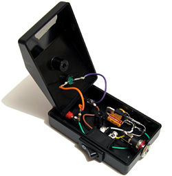
To copy the system files and a sample disk image to the flash memory I cobbled together the above parallel port programmer which is driven by an application cobbled together in C#. It's rather slow but gets the job done — unlike my AVR programmer. After finally managing to get CP/M to boot in a satisfactory manner I made a few tweaks to the AVR program and hit the "Build and Program" button in the editor. The code built, but rather than program the AVR my computer switched off. No error message, not even a blue screen, just a sudden and surprising power down. Since then I've only managed to talk to the AVR once; every other time has resulted in either a power down or blue screen. I had hoped to add some keyboard handling routines to the project to at least be able to interact with CP/M, but after fiddling around for an hour and a half without managing to get anything working again I gave up. I wish I knew why it suddenly stopped working, after hours of reliable service — maybe it's a hint that it's time to buy a proper USB debugger rather than the cheap and cheerful home-made serial port programmer I've been using!
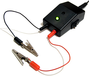
One equally cheap but useful addition to my tools is the above 5V power supply (yes, it's just a 7805 regulator in a box). Every project I have built needs a 5V supply from somewhere, which usually comes from a 7.5V wall wart power supply unit regulated to 5V with a 7805. This takes up valuable breadboard space and the weight of the cable from the power supply tends to drag the breadboard around the smooth surface of my desk, so having a dedicated box with an on-off switch, indicator LED, reverse voltage protection and an easy way to connect to the circuit via 2mm sockets is very handy indeed.
I now need to find a way to program AVRs without my PC switching itself off before I can make any more progress on the project...
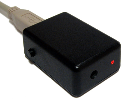
USB remote control receiver for PowerDVD
Monday, 7th June 2010
I enjoy watching films and mainly do so sitting at my desktop PC. This has taught me that cheap office chairs are not the most comfortable things to sit on for extended periods of time, especially when the next room contains a comfortable bean bag and a good place to stick a screen. A gap between the two rooms allows me to pass cables from one to the other, and after purchasing a 10m DVI-D cable and a USB extension lead on eBay I had both picture and sound sorted out (I use a USB sound "card"). This left me with one final problem: how to control the PC through a wall.
One possibility would be to extend the lead on my keyboard, but its media buttons light up (bothersome in a darkened room) and some of the keyboard shortcuts in PowerDVD (such as Ctrl+P for the popup menu when watching Blu-ray discs) are tricky to hit in the dark. Given my fondness for infra-red remote controls building a remote control receiver would seem like both an interesting and useful way to spend a weekend.
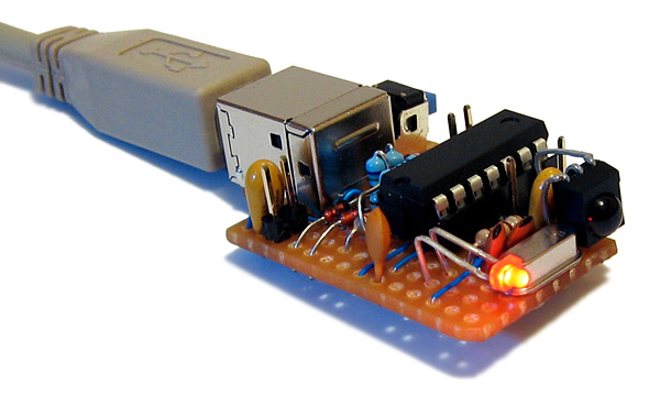
Rather than build something that relied on some Windows software to translate received remote control signals into keystrokes I decided to use the free V-USB library to construct something that showed up in Windows as a standard USB keyboard. One of the sample V-USB projects is a USB keyboard, which made getting started much easier! The above photograph shows the initial prototype, based around an ATmega168. The tall three-legged component sticking up out of the board is a TSOP2438, which is an infra-red receiver and demodulator. This is tuned to the 38kHz carrier employed by most remote controls and outputs a logic low or logic high depending on the presence or absence of such a signal. The ATmega168 is programmed to time the incoming signal and passes this timing information to a collection of routines that attempt to decode it. I have currently two decoders, one for the NEC protocol and another for SIRCS — information about some common protocols can be found on this website.
The choice of these two protocols is down to the remote controls I have around me. The one that offered me the most useful buttons was the PlayStation 2 DVD remote control (SIRCS), though this is missing some useful controls, such as volume and the red, green, yellow and blue buttons. To remedy this I went and bought a cheap universal remote control from Clas Ohlson. After hunting through several of the modes I settled on the Clas Ohlson DVD one (0815) as most of the buttons work in this mode (the only unshifted one that doesn't is the record button, and I can live without it). In this mode the remote control uses the NEC protocol.
To turn the receiver into something more conveniently sized I decided to switch from the 28-pin ATmega168 to the 14-pin ATtiny84, shown in the above photograph. The compiled program was already small enough to fit into the reduced memory, and the only modification I had to make was to amend two timing routines to share the same timer peripheral as the ATtiny84 only has two timers, not the three I'd been using on the ATmega168.
I also opted to add a switch to the design. One problem with supporting both Blu-ray and DVD is that the way you navigate menus is quite different between the two; Blu-ray discs use a simple popup menu (Ctrl+P) which appears on top of the film, whereas DVDs seem to offer a number of different menu commands — the two most common ones being "Title menu" (no shortcut) and "Root menu" (J). PowerDVD also lets you choose from a list of DVD menus in a context menu with one shortcut (L). I set the button on the receiver to switch between "Blu-ray" and "DVD" modes; in Blu-ray mode, the menu button sends Ctrl+P and in DVD mode the menu button sends L.
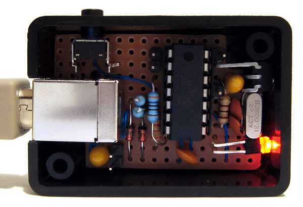
I bought an enclosure that is, in retrospect, a little too small. The above photograph shows the receiver assembled on stripboard with a fairly cramped layout. Fortunately there was sufficient room to include pin headers on the board, which will allow me to plug in a programmer to modify the software should I need to in the future. The LED on the front serves as simple user feedback — it flashes whenever it receives a valid command and sends a keystroke back to the PC. When the mode is toggled between Blu-ray and DVD menus it flashes to indicate the new mode — a long flash followed by a single short one for Blu-ray, a long flash followed by two short ones for DVD.
Overall, I'm quite happy with the way it turned out. It works well enough for my needs, though as those needs only extend as far as PowerDVD and a particular remote control it's rather basic and much more could be done with the hardware. I have uploaded the source code and a schematic for the project to my website as it currently stands for those who are interested.
Superprobe
Saturday, 10th April 2010
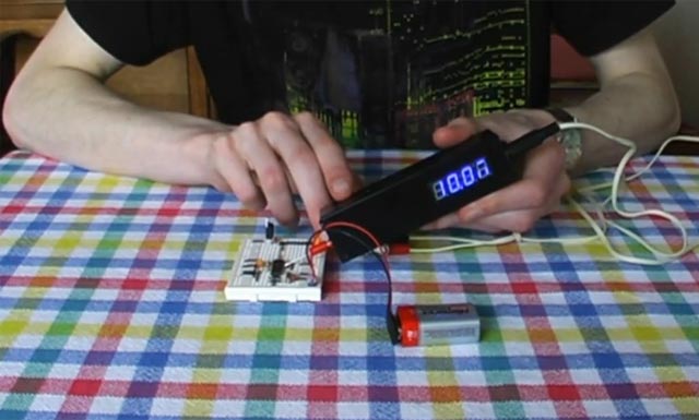
I have recently been working on building my own Superprobe. This is a cheap and simple tool based around a single PIC 16F870, a four-digit display and a handful of other parts. Hardware details and software can be found on the Superprobe section of the Mondo Technology website.
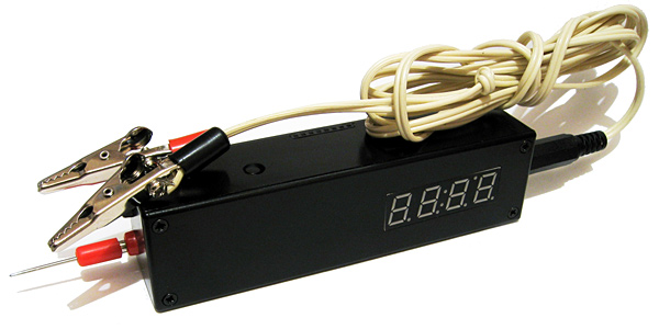
As the name suggests, at its simplest the Superprobe can be used as a logic probe, displaying an L, H or - if it touches a point in the circuit that is in a low, high or floating state. What makes it so "super" is that by using the two input buttons you can switch it to a different mode. The supplied software provides seventeen different modes, including a logic pulser, frequency counter, voltmeter, capacitance meter, signal generator and serial ASCII data output.
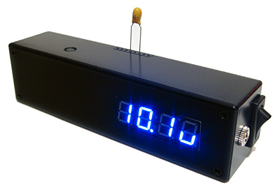
Measuring a 10µF capacitor.
Having such a wide range of functions for such a modest part count made this a very attractive project to build. Unfortunately, I couldn't find a 16F870 so used the pin-compatible 16F876A instead; porting the code from the older microcontroller mainly involved changing the list p=16f870 directive. I did notice that the probe didn't seem to save its settings when powering down as it should, so I copied the EEPROM reading and writing code from the 16F876A datasheet into the source to replace the existing code which seemed to fix it.
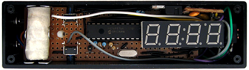
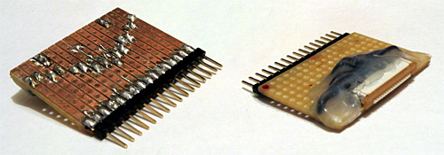
The insides of the Superprobe.
As I couldn't find a suitable low drop-out 5V regulator I opted to use a conventional L7805 regulator. This means that the input voltage has to be at least two volts higher than the output; I normally power circuits from a 7.5V or 9V supply anyway so this isn't too much of a problem. Finding a suitable battery to go inside the case was more of a challenge; there's insufficient room for the typical 9V PP3, sadly. A bit of hunting for "7.5V battery" led me to a suitable battery with a variety of names and a rather high price. Aided by a ruler and the dimensions on the above website it seems that the A175 is exactly the same size as five LR44/AG13 cells stacked on top of eachother (coincidence? I think not). A reputable high street shop noted for the quality of its goods sold a card of forty button cells (including ten AG13 cells), so five of those and a bit of masking tape provided me with a passable imitation. Sparing no expense, the battery holder is constructed from paper clips.
The 16F876A has more program space and SRAM than the 16F870, making developing software in C more viable. Not all of of the original software's features were especially useful to me, and I was likely to want to add new modes myself in the future, so set about reimplementing the functions that I did find handy in C. The result is quite a bit easier to modify; for example, the above photograph demonstrating the measurement of a capacitor shows a value with an SI prefix (10.1u for a 10µF capacitor). All one needs to do to display such a number on the display is call display_print_float(10.1e-6f); – the code does the rest for you. Sadly, this does inflate the size of the code significantly and my current version of the code only squeezes 11 functions into a much larger chip (compared to the 17 on the original).
Measuring a 2.2KΩ resistor.
One of the new modes is a resistance meter. This works by pulling the probe tip high using a known resistance (5KΩ, 10KΩ or 100KΩ) and combining this with the resistor to be measured between the probe tip and ground to form a voltage divider. The output of the voltage divider is measured, and from that the resistance of the resistor being tested can be determined. The ability to use multiplication, division and floating point arithmetic makes this easy to program in C; much more so than it would have been in assembly, at least!
I have recorded a video demonstrating the Superprobe. The code for my variation on the theme can be downloaded here, and can be compiled with the free ("lite") edition of the HI-TECH C compiler.
Controlling a PG320240H-P9 with a dsPIC33FJ128GP802
Sunday, 21st March 2010
In a previous entry I mentioned that I had purchased a PG320240H-P9 graphical LCD. This is a 320×240 white-on-blue pixel display, and it does not have an on-board controller or RAM. To display something on it you need to constantly refresh it with picture data; in this instance, sending four pixels at a time, starting from the top left and working from left to right, top to bottom — a bit like the scanning pattern of a CRT monitor.
Connecting a circuit to the LCD is made slightly more tricky by its use of a 16-pin 1mm flexible flat cable. To get around this I soldered together an adaptor using a suitable FCC connector, pin strip, piece of stripboard and a fairly excessive quantity of hot melt adhesive. Even more tricky was the lack of a suitable datasheet for the LCD. After some digging I located this one for the PG320240WRM-HNNIS1 — it's slightly different, but contains timing diagrams and specifications that seem to work with the LCD I bought. One thing I still haven't worked out is the contrast adjustment; a 5K variable resistor between 0V and the relevant pin seems to have had the best results thus far. A helpful webpage, Graphical LCD controller for ST8024+ST8016 based displays, has a plain English description of how to drive the LCD, though as far as I'm aware the M pin should have its logic level toggled every frame, giving you a "glass" frequency of half of the refresh rate, not 200Hz-400Hz. The lack of a proper datasheet makes these things a little complicated!
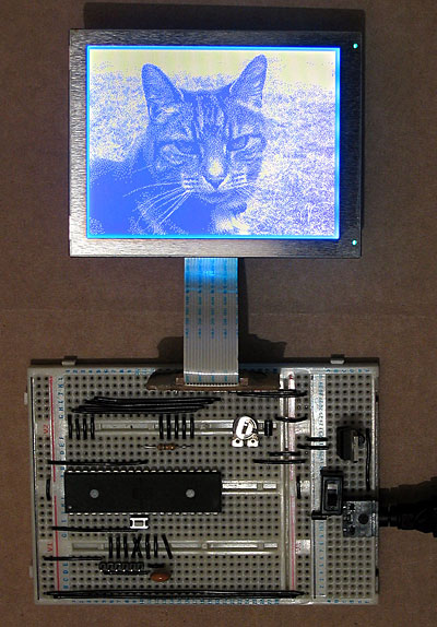
My first attempt to drive the LCD involved an ATmega644P, a microcontroller with 64KB of flash ROM and 4KB of RAM. The above photo shows it displaying a picture of a cat, which was stored in ROM and output using the following code:
#include <stdint.h>
#include <avr/io.h>
#include <avr/pgmspace.h>

#define LCD_FLM   (6)
#define LCD_M     (5)
#define LCD_C1    (4)
#define LCD_C2    (3)
#define LCD_D_OFF (2)

#define LCD_CONTROL_PORT (PORTC)
#define LCD_CONTROL_PIN  (PINC)
#define LCD_CONTROL_DDR  (DDRC)

#define LCD_DATA_PORT    (PORTA)
#define LCD_DATA_PIN     (PINA)
#define LCD_DATA_DDR     (DDRA)

#include "cat.h"

int main(void) {

    // Make control pins outputs.
    LCD_CONTROL_DDR |= _BV(LCD_FLM) | _BV(LCD_M) | _BV(LCD_C1) | _BV(LCD_C2) | _BV(LCD_D_OFF);

    // Make data pins outputs.
    LCD_DATA_DDR |= 0b1111;

    // Enable the LCD.
    LCD_CONTROL_PORT |= _BV(LCD_D_OFF);

    for(;;) {

        // Toggle the M pin to provide the LCD AC voltage.
        LCD_CONTROL_PIN |= _BV(LCD_M);

        const uint8_t* picture_ptr = cat_picture;

        // Scan 240 rows in the image.
        for (uint8_t row = 0; row < 240; ++row) {

            // Begin the line.
            LCD_CONTROL_PIN |= _BV(LCD_C1);
            LCD_CONTROL_PIN |= _BV(LCD_C1);

            if (row < 2) LCD_CONTROL_PIN |= _BV(LCD_FLM);

            // Send 40 eight-bit words.
            for (uint8_t column = 0; column < 40; ++column) {
                LCD_DATA_PORT = pgm_read_byte(picture_ptr) >> 4;
                LCD_CONTROL_PIN |= _BV(LCD_C2);
                LCD_CONTROL_PIN |= _BV(LCD_C2);
                LCD_DATA_PORT = pgm_read_byte(picture_ptr);
                LCD_CONTROL_PIN |= _BV(LCD_C2);
                LCD_CONTROL_PIN |= _BV(LCD_C2);
                ++picture_ptr;
            }
        }
    }

}
A 320×240 display has 76,800 pixels, and if you store each pixel as a single bit (so eight pixels per byte) you need 9600 bytes to store a complete frame, which clearly won't fit in the 4KB offered by the ATmega644P. Rather than upgrade to an AVR with more memory, I jumped to the dsPIC33FJ128GP802, a 16-bit microcontroller with 16KB of RAM. As well as quadrupling the RAM from the ATmega644P it also doubles the program memory (128KB from 64KB) and speed (40 MIPS from 20 MIPS). When working with AVRs I'd been using a slow home-made serial programmer, and rather than continue with this sorry state of affairs (lack of debugging capabilities is never fun, especially when it takes over a minute to program the microcontroller) I treated myself to a PICkit 3 Debug Express.
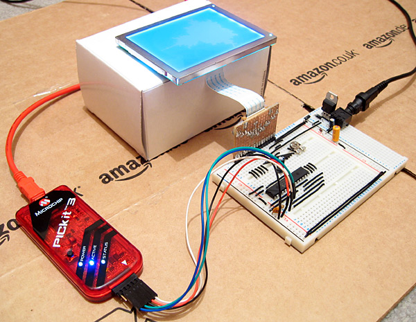
The above photo shows the LCD connected to the microcontroller as well as the PICkit 3. The dsPIC33FJ128GP802 requires a voltage supply from 3.0V to 3.6V, not the 5V I am used to, so to power it I have put two IN4001 rectifier diodes in series with the 5V regulator output. Each diode incurs a voltage drop of 0.7V, producing 3.6V for the rest of the circuit. The LCD is powered from the main 5V supply, but it seems happy with the 3.6V logic "high" from the dsPIC.
The LCD is connected to the dsPIC as follows:
- FLM to RB15
- M to RB14
- C1 to RB13
- C2 to RB12
- /D_OFF to RB11
- D0~D3 to RA0~RA3
A 10K resistor is included between /D_OFF and ground. This is very important, as it holds the /D_OFF line low when RB11 is floating (e.g. during reset), forcing the display off — if the display is powered, but is not being actively refreshed, the LCD panel can become overloaded and damaged.
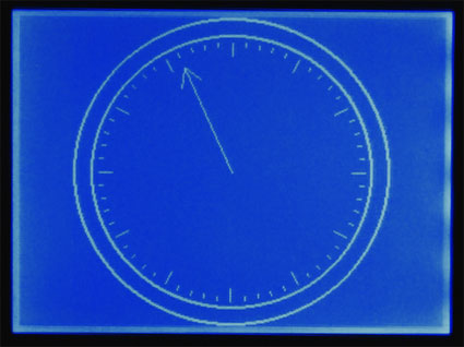
I have knocked together a simple demo that shows a few different graphics on the LCD. The LCD is constantly refreshed by an interrupt service routine that runs in the background, leaving some CPU time to the user program. As there is only enough RAM for a single frame buffer, animation has to be quite simple to avoid flickering, but I've still managed to include my favourite spinning cube.
The project can be downloaded here. I'm still getting to grips with the dsPIC series; the code is likely to be pretty awful, and I still have a problem where the dsPIC resets itself every couple of minutes (I'm not really sure if this is a software or hardware issue). Still, it's a start, and I hope that I can use this LCD as the display for my Z80 computer project.
Update: Having seen this post, the chap who originally suggested that I investigate the dsPIC33FJ128GP802 sent me an email with some advice, chiefly about my poor power supply, missing decoupling capacitors and use of an electrolytic capacitor on the VCAP pin. I have since replaced the two rectifier diode affair with a proper 3.3V regulator for the power supply, added a decoupling capacitor across AVDD/AVSS and moved the decoupling capacitor between VDD/VSS closer to the microcontroller. I have also ordered some tantalum capacitors to replace the electrolytic one. A bit of debugging found that the watchdog timer is responsible for the spurious resets; I have disabled it in the code for the time being, which has stopped the resets.
Adding more stereoscopic modes to Quake II's OpenGL renderer
Thursday, 11th March 2010
Quake II's OpenGL renderer supports stereoscopic rendering providing you own a video card that has the requisite hardware and driver support ("quad-buffered" OpenGL rather than a single front and back buffer you have two front buffers and two back buffers, one for each eye). Not owning such a video card I decided to have a go at adding some other stereoscopic rendering modes that worked with regular hardware.
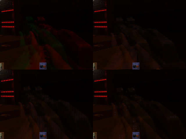
The four new stereoscopic rendering modes
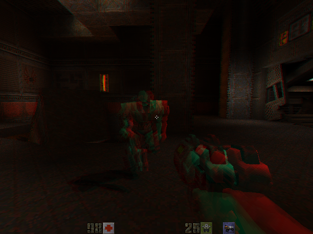
The ability to enable or disable drawing with a particular colour component in OpenGL makes implementing an anaglyph mode very simple temporarily switch off red when drawing the view from one eye and temporarily switch off blue and green when drawing the view from the other to produce a final image that can be used with red/cyan 3D glasses. A new string console variable cl_stereo_anaglyph_colors can be amended to set the colour of your particular glasses, e.g. mg for magenta/green.
By drawing a mask to the stencil buffer before rendering one can easily add "interleaved" modes; there's the standard row interleaved format, but I've also added column and pixel interleaved formats.
It looks like the stereoscopic OpenGL code was started but not finished in Quake II; there were a number of odd bugs, such as the viewport position being changed instead of the camera position when drawing the left and right eye views (producing two views that were offset in 2D, not 3D). A snippet of code hints towards why this may be:
#if 0 // commented out until H3D pays us the money they owe us
    GL_DrawStereoPattern();
#endif
H3D manufactured a VGA adaptor for 3D glasses which relied on a special pattern being displayed on the screen to enable it and switch it to the correct mode rather than let the user do so. H3D went bust toward the end of 1998, so I guess id software never got their money and that function has been commented out ever since.
The new binaries can be downloaded from the Stereo Quake page, and the source can be found on Google Code.