ATmega644P CHIP-8/SCHIP interpreter
Sunday, 7th March 2010
In an attempt to solve the screen resolution problem issue I've bought a very cheap 320×240 pixel graphical LCD – a PG320240H-P9 on eBay for $24. Part of the reason for its cheapness may be down to its the lack of a controller; you need to constantly refresh the LCD with pixel data yourself (easier to use modules have integrated controllers that refresh the display for you from some on-board RAM). If I manage to get it working I'll have a 128×64 pixel graphical LCD going spare – finding a use for it could make an interesting project.
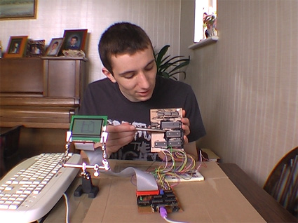
I have a bit of a soft spot for the CHIP-8 programming language, having previously written an few implementations. The CHIP-8 environment requires just under 3.5KB of RAM, and my recent investment in an ATmega644P boasting 4KB of RAM provided me with a microcontroller that was up to the task.
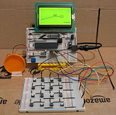
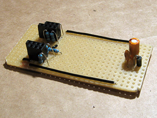
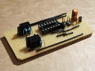
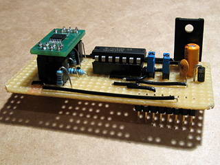
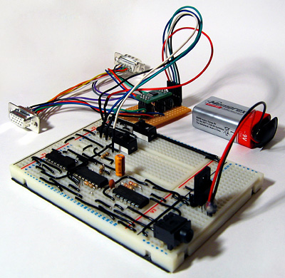
Beyond the ATmega644P and LCD the hardware is pretty simple; a potentiometer is provided to adjust the speed of the interpreter when it's running, from 1/8th speed up to 8× speed. Sound is output using a piezo transducer, which I've taped to the hard plastic lid from a tube of chocolates to amplify it. Games rely on a 4×4 hex keypad for input, and as I do not have a 4×4 keypad – hex or otherwise – I assembled my own on another breadboard. I don't even have sixteen switches of the same type, hence the mixture in the above photo. A schematic of the hardware can be downloaded in PDF format.
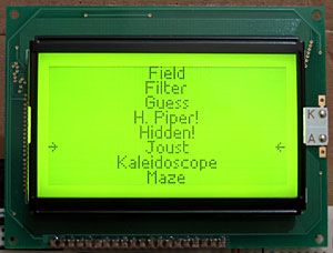
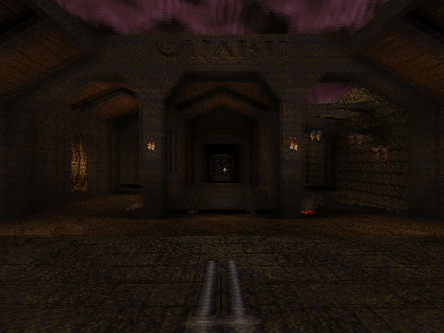
When you reset the circuit a list of all of the programs stored on the microcontroller is shown on the LCD. The 64KB of flash memory on the ATmega644P is enough to store the code for the interpreter and all of the CHIP-8 and SCHIP games available on the Internet. For a change I've decided to have a go at designing a variable width font rather than use one of my existing fixed-width fonts; I don't think it looks too shabby.
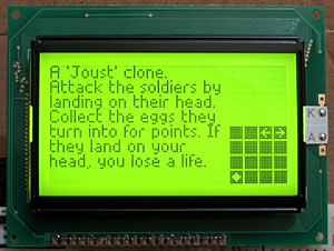
When a game has been selected a (gramatically incorrect) summary of the game is shown. To the right of the screen is a 4×4 grid informing the player which key does what; arrows for directional controls, a diamond for "fire" or confirmation actions and a tick/cross for yes/no input. There doesn't seem to be any particular convention for keypad input in CHIP-8/SCHIP games, which makes this feature invaluable!
Thinking about CP/M
Wednesday, 24th February 2010
It's been some time since I worked on my Z80 computer project, but the recent electronics projects I've completed have got me thinking about it again.
I did record a video to demonstrate the basic parts of the computer and some of its flaws a few months ago, which can be seen above. However, I'm now thinking of a more radical redesign than fixing the I/O board's shortcomings.
One of the reasons for my lack of motivation is that even if I did get something working I wouldn't have much software to run on it; it would be a lot of work to write software that only ran on that one particular machine. BBC BASIC helps somewhat, but an even better solution would be to model the device on an existing machine and run its operating system on it.
Fortunately, there was a popular operating system for the 8080 (and, by extension, the Z80) – CP/M. This is a very simple operating system that inspired DOS. Crucially, it is not hardware-specific, the source code is available and there is a wide range of software available for it, including BBC BASIC.
CP/M is made up of three main components. At the highest level is the Console Command Processor, or CCP. This provides the command-line interface, a handful of built-in commands and handles loading and executing external programs. It achieves this with the aid of the Basic Disk Operating System, or BDOS, which exposes a number of useful routines for a variety of tasks, such as outputting text to the display, searching for files on the disk or reading console input.
Both of the above components are machine-independent – they simply need to be copied to the correct address in RAM when the computer starts. Relocating them to a particular address requires setting a single value in their respective source files and reassembling them, which is nice and easy. It's the third component – the Basic I/O System, or BIOS – that requires a bit more work. This is the only part that is tailored to a particular machine's hardware, and my current implementation is listed below.
CCP    = $DC00
BDOS   = $E406
BIOS   = $F200

IOBYTE = $0003
CDISK  = $0004

DMAAD  = $0008
CTRACK = $000A
CSEC   = $000C

.org BIOS

	jp BOOT    ; COLD START
WBOOTE
	jp WBOOT   ; WARM START
	jp CONST   ; CONSOLE STATUS
	jp CONIN   ; CONSOLE CHARACTER IN
	jp CONOUT  ; CONSOLE CHARACTER OUT
	jp LIST    ; LIST CHARACTER OUT
	jp PUNCH   ; PUNCH CHARACTER OUT
	jp READER  ; READER CHARACTER OUT
	jp HOME    ; MOVE HEAD TO HOME POSITION
	jp SELDSK  ; SELECT DISK
	jp SETTRK  ; SET TRACK NUMBER
	jp SETSEC  ; SET SECTOR NUMBER
	jp SETDMA  ; SET DMA ADDRESS
	jp READ    ; READ DISK
	jp WRITE   ; WRITE DISK
	jp LISTST  ; RETURN LIST STATUS
	jp SECTRAN ; SECTOR TRANSLATE

DISKPARAM
	.dw $0000  ; No sector translation.
	.dw $0000  ; Scratch
	.dw $0000  ; Scratch
	.dw $0000  ; Scratch
	.dw DIRBUF ; Address of a 128-byte scratch pad area for directory operations within BDOS. All DPHs address the same scratch pad area.
	.dw DPBLK  ; Address of a disk parameter block for this drive. Drives with identical disk characteristics address the same disk parameter block.
	.dw CHK00  ; Address of a scratch pad area used for software check for changed disks. This address is different for each DPH.
	.dw ALL00  ; Address of a scratch pad area used by the BDOS to keep disk storage allocation information. This address is different for each DPH.

DIRBUF
	.fill 128

DPBLK           ; DISK PARAMETER BLOCK, COMMON TO ALL DISKS
	.DW 26      ; SECTORS PER TRACK
	.DB 3       ; BLOCK SHIFT FACTOR
	.DB 7       ; BLOCK MASK
	.DB 0       ; NULL MASK
	.DW 242     ; DISK SIZE-1
	.DW 63      ; DIRECTORY MAX
	.DB 192     ; ALLOC 0
	.DB 0       ; ALLOC 1
	.DW 16      ; CHECK SIZE
	.DW 2       ; TRACK OFFSET

CHK00
	.fill 16

ALL00
	.fill 31

; =========================================================================== ;
; BOOT                                                                        ;
; =========================================================================== ;
; The BOOT entry point gets control from the cold start loader and is         ;
; responsible for basic system initialization, including sending a sign-on    ;
; message, which can be omitted in the first version.                         ;
; If the IOBYTE function is implemented, it must be set at this point.        ;
; The various system parameters that are set by the WBOOT entry point must be ;
; initialized, and control is transferred to the CCP at 3400 + b for further  ;
; processing. Note that register C must be set to zero to select drive A.     ;
; =========================================================================== ;
BOOT
	xor a
	ld (IOBYTE),a
	ld (CDISK),a
	jp GOCPM

; =========================================================================== ;
; WBOOT                                                                       ;
; =========================================================================== ;
; The WBOOT entry point gets control when a warm start occurs.                ;
; A warm start is performed whenever a user program branches to location      ;
; 0000H, or when the CPU is reset from the front panel. The CP/M system must  ;
; be loaded from the first two tracks of drive A up to, but not including,    ;
; the BIOS, or CBIOS, if the user has completed the patch. System parameters  ;
; must be initialized as follows:                                             ;
;                                                                             ;
; location 0,1,2                                                              ;
;     Set to JMP WBOOT for warm starts (000H: JMP 4A03H + b)                  ;
;                                                                             ;
; location 3                                                                  ;
;     Set initial value of IOBYTE, if implemented in the CBIOS                ;
;                                                                             ;
; location 4                                                                  ;
;     High nibble = current user number, low nibble = current drive           ;
;                                                                             ;
; location 5,6,7                                                              ;
;     Set to JMP BDOS, which is the primary entry point to CP/M for transient ;
;     programs. (0005H: JMP 3C06H + b)                                        ;
;                                                                             ;
; Refer to Section 6.9 for complete details of page zero use. Upon completion ;
; of the initialization, the WBOOT program must branch to the CCP at 3400H+b  ;
; to restart the system.                                                      ;
; Upon entry to the CCP, register C is set to thedrive;to select after system ;
; initialization. The WBOOT routine should read location 4 in memory, verify  ;
; that is a legal drive, and pass it to the CCP in register C.                ;
; =========================================================================== ;
WBOOT

GOCPM
	ld a,$C3      ; C3 IS A JMP INSTRUCTION
	ld ($0000),a  ; FOR JMP TO WBOOT
	ld hl,WBOOTE  ; WBOOT ENTRY POINT
	ld ($0001),hl ; SET ADDRESS FIELD FOR JMP AT 0

	ld ($0005),a  ; FOR JMP TO BDOS
	ld hl,BDOS    ; BDOS ENTRY POINT
	ld ($0006),hl ; ADDRESS FIELD OF JUMP AT 5 TO BDOS

	ld bc,$0080   ; DEFAULT DMA ADDRESS IS 80H
	call SETDMA

	ei            ; ENABLE THE INTERRUPT SYSTEM
	ld a,(CDISK)  ; GET CURRENT DISK NUMBER
	ld c,a        ; SEND TO THE CCP
	jp CCP        ; GO TO CP/M FOR FURTHER PROCESSING

; =========================================================================== ;
; CONST                                                                       ;
; =========================================================================== ;
; You should sample the status of the currently assigned console device and   ;
; return 0FFH in register A if a character is ready to read and 00H in        ;
; register A if no console characters are ready.                              ;
; =========================================================================== ;
CONST
	out (2),a \ ret

; =========================================================================== ;
; CONIN                                                                       ;
; =========================================================================== ;
; The next console character is read into register A, and the parity bit is   ;
; set, high-order bit, to zero. If no console character is ready, wait until  ;
; a character is typed before returning.                                      ;
; =========================================================================== ;
CONIN
	out (3),a \ ret

; =========================================================================== ;
; CONOUT                                                                      ;
; =========================================================================== ;
; The character is sent from register C to the console output device.         ;
; The character is in ASCII, with high-order parity bit set to zero. You      ;
; might want to include a time-out on a line-feed or carriage return, if the  ;
; console device requires some time interval at the end of the line (such as  ;
; a TI Silent 700 terminal). You can filter out control characters that cause ;
; the console device to react in a strange way (CTRL-Z causes the Lear-       ;
; Siegler terminal to clear the screen, for example).                         ;
; =========================================================================== ;
CONOUT
	out (4),a \ ret

; =========================================================================== ;
; LIST                                                                        ;
; =========================================================================== ;
; The character is sent from register C to the currently assigned listing     ;
; device. The character is in ASCII with zero parity bit.                     ;
; =========================================================================== ;
LIST
	out (5),a \ ret

; =========================================================================== ;
; PUNCH                                                                       ;
; =========================================================================== ;
; The character is sent from register C to the currently assigned punch       ;
; device. The character is in ASCII with zero parity.                         ;
; =========================================================================== ;
PUNCH
	out (6),a \ ret

; =========================================================================== ;
; READER                                                                      ;
; =========================================================================== ;
; The next character is read from the currently assigned reader device into   ;
; register A with zero parity (high-order bit must be zero); an end-of-file   ;
; condition is reported by returning an ASCII CTRL-Z(1AH).                    ;
; =========================================================================== ;
READER
	out (7),a \ ret

; =========================================================================== ;
; HOME                                                                        ;
; =========================================================================== ;
; The disk head of the currently selected disk (initially disk A) is moved to ;
; the track 00 position. If the controller allows access to the track 0 flag  ;
; from the drive, the head is stepped until the track 0 flag is detected. If  ;
; the controller does not support this feature, the HOME call is translated   ;
; into a call to SETTRK with a parameter of 0.                                ;
; =========================================================================== ;
HOME
	ld bc,0
	jp SETTRK

; =========================================================================== ;
; SELDSK                                                                      ;
; =========================================================================== ;
; The disk drive given by register C is selected for further operations,      ;
; where register C contains 0 for drive A, 1 for drive B, and so on up to 15  ;
; for drive P (the standard CP/M distribution version supports four drives).  ;
; On each disk select, SELDSK must return in HL the base address of a 16-byte ;
; area, called the Disk Parameter Header, described in Section 6.10.          ;
; For standard floppy disk drives, the contents of the header and associated  ;
; tables do not change; thus, the program segment included in the sample      ;
; CBIOS performs this operation automatically.                                ;
;                                                                             ;
; If there is an attempt to select a nonexistent drive, SELDSK returns        ;
; HL = 0000H as an error indicator. Although SELDSK must return the header    ;
; address on each call, it is advisable to postpone the physical disk select  ;
; operation until an I/O function (seek, read, or write) is actually          ;
; performed, because disk selects often occur without ultimately performing   ;
; any disk I/O, and many controllers unload the head of the current disk      ;
; before selecting the new drive. This causes an excessive amount of noise    ;
; and disk wear. The least significant bit of register E is zero if this is   ;
; the first occurrence of the drive select since the last cold or warm start. ;
; =========================================================================== ;
SELDSK
	ld hl,DISKPARAM
	ld a,c
	or a
	ret z
	ld hl,$0000 ; Only disc 0 is supported.
	ret

; =========================================================================== ;
; SETTRK                                                                      ;
; =========================================================================== ;
; Register BC contains the track number for subsequent disk accesses on the   ;
; currently selected drive. The sector number in BC is the same as the number ;
; returned from the SECTRAN entry point. You can choose to seek the selected  ;
; track at this time or delay the seek until the next read or write actually  ;
; occurs. Register BC can take on values in the range 0-76 corresponding to   ;
; valid track numbers for standard floppy disk drives and 0-65535 for         ;
; nonstandard disk subsystems.                                                ;
; =========================================================================== ;
SETTRK
	ld (CTRACK),bc
	ret

; =========================================================================== ;
; SETSEC                                                                      ;
; =========================================================================== ;
; Register BC contains the sector number, 1 through 26, for subsequent disk   ;
; accesses on the currently selected drive. The sector number in BC is the    ;
; same as the number returned from the SECTRAN entry point. You can choose to ;
; send this information to the controller at this point or delay sector       ;
; selection until a read or write operation occurs.                           ;
; =========================================================================== ;
SETSEC
	ld (CSEC),bc
	ret

; =========================================================================== ;
; SETDMA                                                                      ;
; =========================================================================== ;
; Register BC contains the DMA (Disk Memory Access) address for subsequent    ;
; read or write operations. For example, if B = 00H and C = 80H when SETDMA   ;
; is called, all subsequent read operations read their data into 80H through  ;
; 0FFH and all subsequent write operations get their data from 80H through    ;
; 0FFH, until the next call to SETDMA occurs. The initial DMA address is      ;
; assumed to be 80H. The controller need not actually support Direct Memory   ;
; Access. If, for example, all data transfers are through I/O ports, the      ;
; CBIOS that is constructed uses the 128 byte area starting at the selected   ;
; DMA address for the memory buffer during the subsequent read or write       ;
; operations.                                                                 ;
; =========================================================================== ;
SETDMA
	ld (DMAAD),bc
	ret

; =========================================================================== ;
; READ                                                                        ;
; =========================================================================== ;
; Assuming the drive has been selected, the track has been set, and the DMA   ;
; address has been specified, the READ subroutine attempts to read one sector ;
; based upon these parameters and returns the following error codes in        ;
; register A:                                                                 ;
;                                                                             ;
;     0 - no errors occurred                                                  ;
;     1 - nonrecoverable error condition occurred                             ;
;                                                                             ;
; Currently, CP/M responds only to a zero or nonzero value as the return      ;
; code. That is, if the value in register A is 0, CP/M assumes that the disk  ;
; operation was completed properly. If an error occurs the CBIOS should       ;
; attempt at least 10 retries to see if the error is recoverable. When an     ;
; error is reported the BDOS prints the message BDOS ERR ON x: BAD SECTOR.    ;
; The operator then has the option of pressing a carriage return to ignore    ;
; the error, or CTRL-C to abort.                                              ;
; =========================================================================== ;
READ
	out (13),a \ ret

; =========================================================================== ;
; WRITE                                                                       ;
; =========================================================================== ;
; Data is written from the currently selected DMA address to the currently    ;
; selected drive, track, and sector. For floppy disks, the data should be     ;
; marked as nondeleted data to maintain compatibility with other CP/M         ;
; systems. The error codes given in the READ command are returned in register ;
; A, with error recovery attempts as described above.                         ;
; =========================================================================== ;
WRITE
	out (14),a \ ret

; =========================================================================== ;
; LISTST                                                                      ;
; =========================================================================== ;
; You return the ready status of the list device used by the DESPOOL program  ;
; to improve console response during its operation. The value 00 is returned  ;
; in A if the list device is not ready to accept a character and 0FFH if a    ;
; character can be sent to the printer. A 00 value should be returned if LIST ;
; status is not implemented.                                                  ;
; =========================================================================== ;
LISTST
	out (15),a \ ret

; =========================================================================== ;
; SECTRAN                                                                     ;
; =========================================================================== ;
; Logical-to-physical sector translation is performed to improve the overall  ;
; response of CP/M. Standard CP/M systems are shipped with a skew factor of   ;
; 6, where six physical sectors are skipped between each logical read         ;
; operation. This skew factor allows enough time between sectors for most     ;
; programs to load their buffers without missing the next sector. In          ;
; particular computer systems that use fast processors, memory, and disk      ;
; subsystems, the skew factor might be changed to improve overall response.   ;
; However, the user should maintain a single-density IBM-compatible version   ;
; of CP/M for information transfer into and out of the computer system, using ;
; a skew factor of 6.                                                         ;
;                                                                             ;
; In general, SECTRAN receives a logical sector number relative to zero in BC ;
; and a translate table address in DE. The sector number is used as an index  ;
; into the translate table, with the resulting physical sector number in HL.  ;
; For standard systems, the table and indexing code is provided in the CBIOS  ;
; and need not be changed.                                                    ;
; =========================================================================== ;
SECTRAN
	ld h,b
	ld l,c
	ret
Quite a number of the above routines simply output the value of the accumulator to a port. This is because I'm running CP/M in a Z80 emulator that I've knocked together, and am handling writes to particular ports by implementing the machine-specific operations (such as console input or output) in C#. The floppy disk file system is also emulated in C#; when the program starts, it pulls all the files from a specified directory into an in-memory disk image. Writing to any sector deletes all of the files in this directory then extracts the files from the in-memory virtual disk image back into it. This is not especially efficient, but it works rather well.
To turn this into a working bit of hardware, I intend to replace the C# part with a microcontroller to handle keyboard input, text output and interfacing to an SD card for file storage. It would also be responsible for booting the system by copying the OS to Z80 memory from the SD card. I'm not sure the best way to connect the microcontroller to the Z80, though; disk operations use DMA, which is easy enough, but for lighter tasks such as querying whether console input is available or outputting a character to the display it would be nice to be able to go via I/O ports. A couple of I/O registers may be sufficient as per the current design; a proper Z80 PIO would be even better if I can get my hands on one.
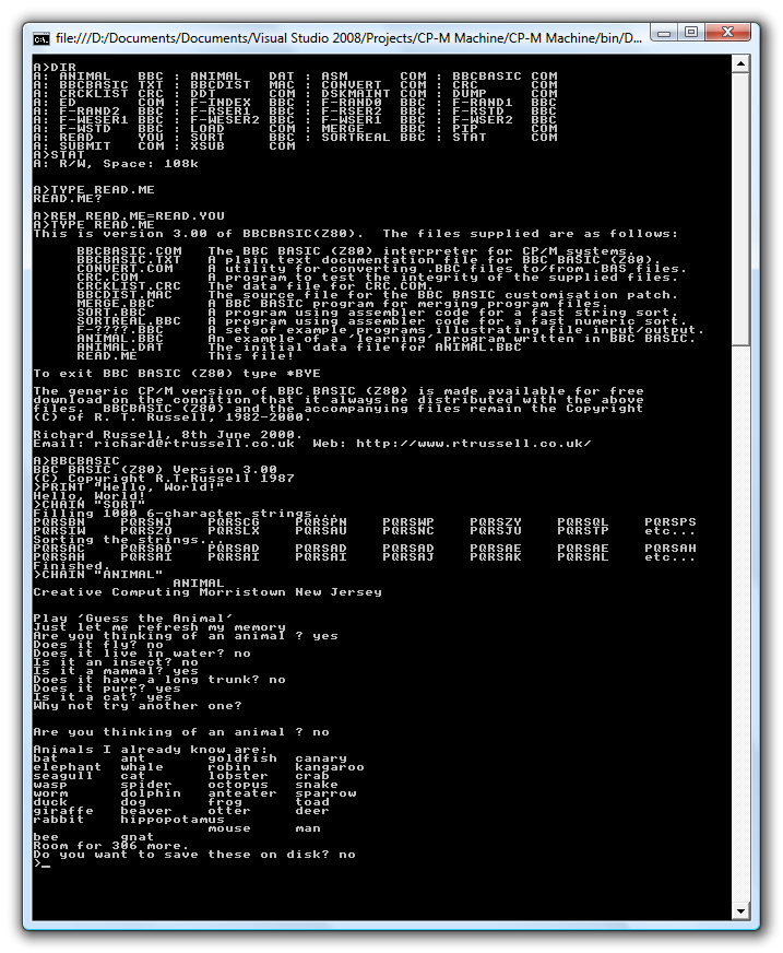
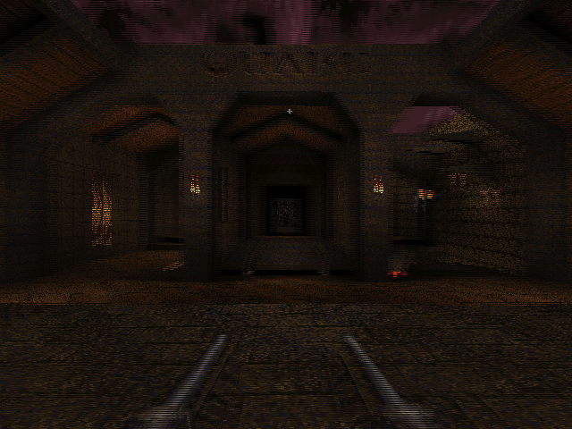
Of more concern is a suitable display; the above screenshot is from an 80-character wide display. Assuming a character was four pixels wide (which is about as narrow as they can be made whilst still being legible) imposes a minimum resolution of 320 pixels horizontally – my current LCD is only 128 pixels wide (not even half way there), and larger ones are really rather expensive!
Building a VGA line blanker and 3D glasses driver
Monday, 15th February 2010
Assembling a circuit on breadboard is a good way to experiment with electronics, but the result is not something you could really use – it's bulky, fragile and awkward to set up. It's far nicer to solder the components of the circuit together to form a more permanent device and put it in a enclosure to make it robust. This is not something I'm especially good at, but something I thought I'd try with the VGA line blanker and LCD shutter glasses controller I've been experimenting with recently.
In the past I've struggled along with a hand drill and the nail file on a Swiss Army knife, but have more recently acquired a high-speed rotary tool and an assortment of attachments which make things much easier. I took some photos when building this project, which I've documented below; I'm not sure my techniques are very efficient, but I do get there in the end. I'd be very glad to hear any advice anyone has!
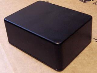
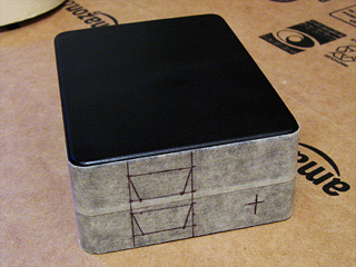
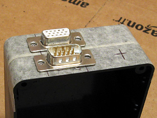
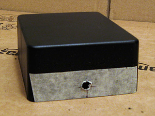
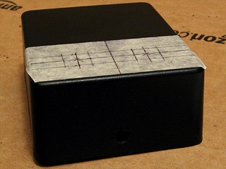
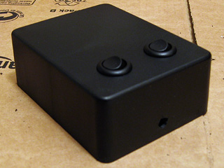
I started with a plain project box. Having planned roughly where I was going to put the VGA ports and DC power socket, I covered one side of the box in masking tape and drew on where I was going to put the holes.
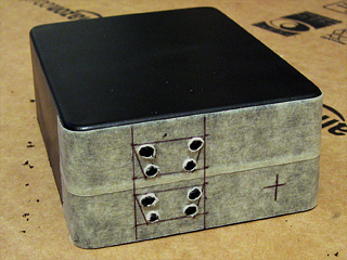
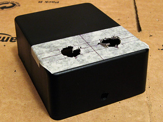
To cut straight-edged holes, such as those required for a D-subminiature connector, I drill a hole in each corner and use a small cylindrical burr to cut between the holes. This leaves a very rough edge, but is a good start.
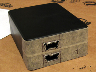
I then widen the hole using a large cylindrical burr and a needle file until the part I'm attempting to mount fits snugly.
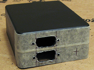
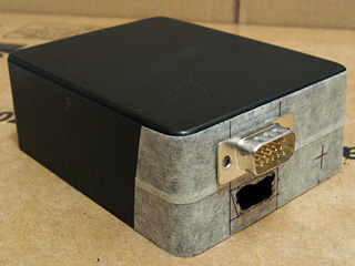
When I had both VGA connectors in place, I marked and drilled the holes for the jack posts that the VGA leads will screw into. Neither hole is especially neatly cut, but the D-subminiature connector overlaps the hole sufficiently to hide any shoddy workmanship.
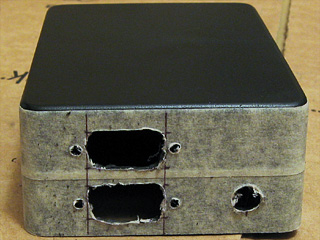
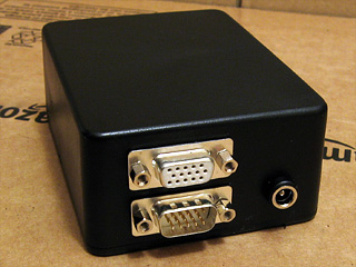
The last part of the back is the DC power socket. As I don't have a drill bit large enough to cut the hole on its own, I drill it as large as I can then widen it using the cylindrical burrs mentioned before. With all of the holes cut, I inserted the components to see how they look and identified one problem – I'd underestimated how fat the connectors on the end of VGA leads are. Fortunately, I have a slim VGA cable that fits, but a regular sized one does not – in future I'll need to remember to put the VGA connectors further apart!
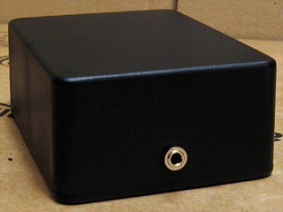
With that mistake fresh in my mind, I thought I'd move onto something a bit more difficult to get wrong – the 3.5mm stereo jack on the front of the box to plug the glasses into. This is just another round hole, cut in the same way as the DC power socket.
The two control switches on the top of the box require much larger holes. These were cut in the same way as before – a small hole is gradually widened by using a cylindrical burr. This is a very tedious job, not helped by having to keep stopping to clean the melted plastic that adheres to the burr.
Finally, the switches were installed. I was originally going to use latching push buttons, but had previously used those nice round rocker switches as the power switch on the AVR TV Game project so opted to use them instead.
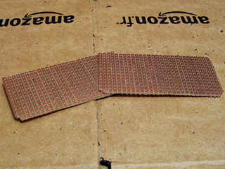
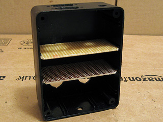
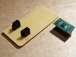
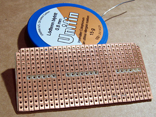
The final bit of physical work was to cut some stripboard down to size to fit inside the enclosure. These were cut by first scoring along the tracks where the cut was to be made, then snapping the board over the edge of a table. This results in a clean break, but to ensure a snug fit the boards were tidied up with a sanding drum. The lid (or, in my case, base) of the enclosure has a raised edge that fits inside the box, so the sanding drum was also used to remove two of the corners of the stripboard pieces to allow the base to fit.
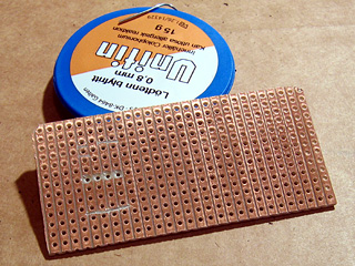
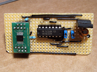
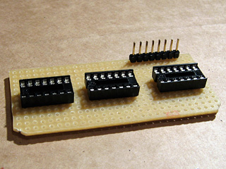
The next stage was to move onto the electronics, and I started with the circuit board that was to host the video amplifier IC, voltage regulator and Schmitt trigger on vsync/hsync. The video amplifier is attached to a TSSOP14 adaptor that has a D-shaped pin configuration, with two rows of four pins and two rows of three pins. Having cut through the tracks in the stripboard to mount the amplifier, I needed to find some suitable pin sockets.

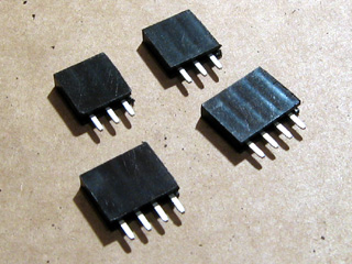
As I don't have any pin sockets with just three pins in them (only two, four and eight) I cut two eight-way pin sockets in two with a pair of wire cutters then tidied up the ragged edges with a sanding drum and needle file.
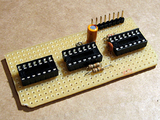
With the pin sockets soldered in place you can see the D shape I mentioned above. I don't generally plan stripboard circuits very thoroughly, preferring to start by placing large components in approximately the right location with respect to where the external connectors are and how they need to relate to other components. Once those are in place I add smaller components (such as discrete resistors or capacitors) before finishing by adding the wire links to connect all of the parts together. This does lead to situations where I wish that I'd placed a component one hole along to give myself more space or to avoid having to insert so many wire links, but it generally works.
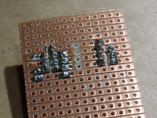
With the video amplifier in position, I added the resistors that are required on its inputs and outputs. To keep the circuit reasonably compact I cut through stripboard tracks between the holes using a conical HSS burr with a small tip – this is an especially useful tool when you need to deal with double-row pin sockets
I then added the support circuitry for the voltage regulator (smoothing capacitors and a rectifier diode to protect the circuit if the polarity of the power supply is incorrect) and a socket for the Schmitt trigger IC. I find the easiest way to keep components in place on any sort of through-hole board is to tape them down firmly with masking tape before soldering – bending the legs out makes the parts much harder to remove if you make a mistake. Blu-Tack is easier to use but has a habit of melting when soldering and leaving an unpleasant blue residue on your circuit, so I'd advise against it! To make this part of the circuit slightly more future-proof a pair of jumpers are used to connect the sync lines (vsync and hsync) from the VGA input and VGA output together. These could be removed if I decided to change the logic board to override these signals – for example, as part of a sync-doubler, which injects a vsync pulse half way down the screen.
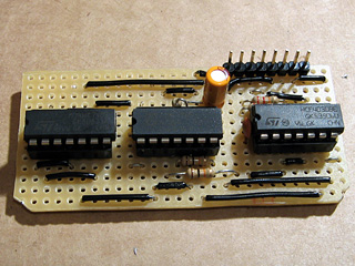
I finally added the bulkiest components; the 5V regulator and the pin header to connect the upper and lower boards together. Soldering pin headers to the underside of a board is a fiddly job, but is required in this instance to connect the bottom of the upper board to the top of the lower board.
With the upper board completed it was time to put it into the enclosure and solder the VGA connectors and DC power socket to it. This is the part I least enjoy.
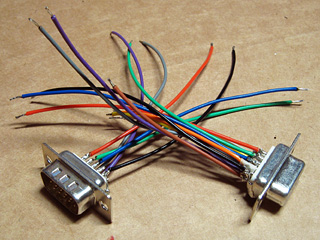
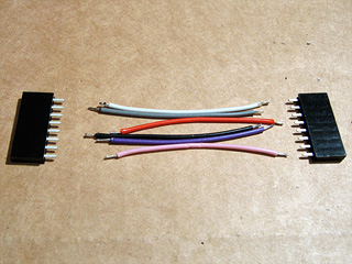
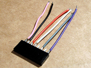
I started by soldering some stranded wire to the VGA connectors. Most of the wires are the same length, as they are required to carry signals to and from the circuit, but some wires are shorter and only connected to one of the VGA connectors. These are the white, yellow, orange and brown wires in the above photo, and these are attached to pins used to exchange information between the PC and the monitor (e.g. supported resolutions and refresh rates). As we're not interested in these, they're connected straight through from one connector to the other.
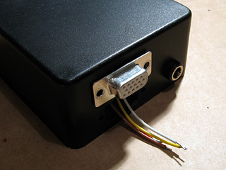
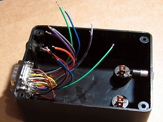
I inserted the VGA connector with these identification pins into the top hole, passed the shorter identification wires through the other and soldered them to the second VGA connector. This leaves the red, green, blue, vsync, hsync and ground pins loose inside, ready to be connected to the upper circuit board.
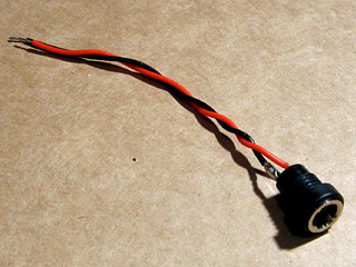
The DC power socket also needs to be connected to the circuit board, but at only two wires that's a much simpler job.
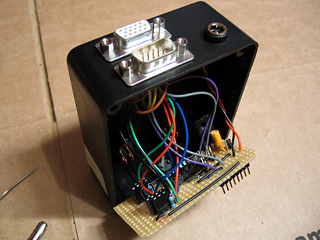
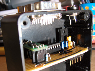
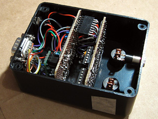
All of the loose leads are soldered onto the circuit board and stripboard is slotted into place inside the enclosure. The wires could be shorter, but that would have made soldering them a bit harder.
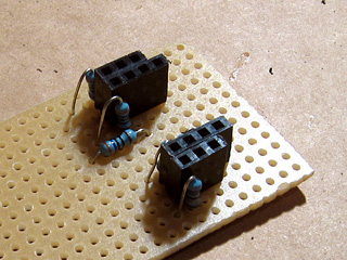
The lower circuit board will host the main logic for the project – it receives the vsync and hsync signals, and uses these to control whether the video signal should be blanked or not, and which shutter on the glasses should be closed and which should be open. It also contains the oscillator that generates the AC voltage that drives the glasses. I arranged the three logic ICs roughly next to eachother according to their layout on the breadboard version of the circuit and cut the stripboard tracks as appropriate.
I started by adding the sockets for the ICs and pin header to connect this circuit board to the video amplifier one, then added the discrete components. As before, I taped the components down before soldering them in place to make the task easier. Being able to copy the circuit directly from the breadboard version also made the task much easier.
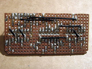
The last step for this part of the project was, as before, adding the wire links. Rather than run long wires around ICs I found it more practical to solder a few wires onto the underside of the stripboard.
The two circuit boards needed to be connected together somehow. Without the facilities to make a proper ribbon cable, I just soldered some lengths of stranded wire (rather messily) between two pin sockets. As I'm not outputting anything to vsync or hsync (I'm feeding the input sync signals straight back to the output via the jumpers previously discussed), I didn't need to connect anything to these pins – hence the apparently missing wires in the photos.
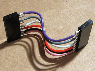
The cable to connect the two boards together needed to be bent to fit – it's getting snug, but everything's in there without having to be forced, which is a good sign.
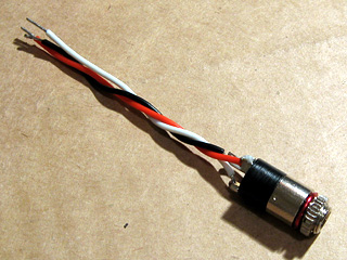
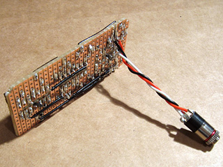
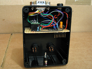
The next job was to attach the 3.5mm stereo jack that the LCD shutter glasses are plugged into. This is pushed through the hole in the enclosure from the inside and screwed on from the outside, so it can be soldered directly to the circuit board without having to thread it through the hole first. The small red "washer" is a length of enamelled wire that has been bent around the thread of the jack socket and is used as a spacer – without it, quite a lot of the thread protrudes from the front of the box, looking rather untidy.
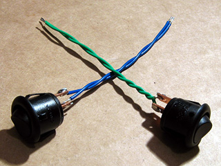
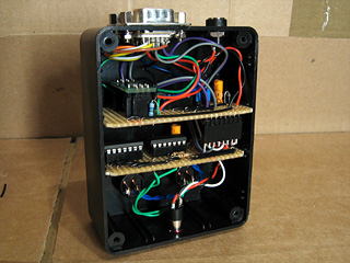
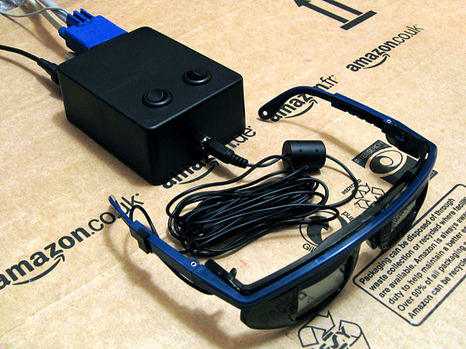
Last of all are the two control switches. These are soldered to the track side of the stripboard like the stereo jack, but must be snapped through their holes in the enclosure first, which is why they were left until last. Everything is slotted into place, the base of the enclosure is screwed on, and the project is pretty much complete.
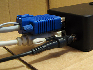
The VGA cables don't fit especially well – the D-subminiature sockets are a bit too close to eachother. If I use a thin VGA extension cable and wiggle the leads I can just about get both to screw in.
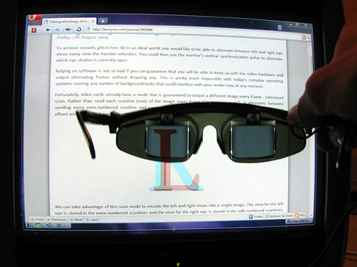
The demonstration pattern from some previous ramblings of mine is quite useful for testing 3D glasses, and by holding the left eye of the shutter glasses to the screen you can see that only the "L" part of the image is let through.
Adding a stereoscopic renderer to Quake II
Sunday, 7th February 2010
Having tweaked the stereoscopic rendering code in Quake, I decided to have a go at Quake II. This doesn't natively support row-interleaved stereoscopic rendering, but I thought that the shared code base of Quake and Quake II should make extending Quake II relatively simple.
Quake II does have two console variables dedicated to stereoscopic rendering already, cl_stereo (enable/disable stereoscopic rendering) and cl_stereo_separation (controls the displacement of the camera between eyes; the same as LCD_X in Quake). These variables only seem to be used in the OpenGL renderer, though I haven't been able to get them to do anything meaningful – I have a hunch that you need a video card that supports stereoscopic rendering; these do exist, and have a socket on them for 3D glasses, but I'm having to make do with my DIY hardware. Furthermore, I've always found the OpenGL rendering in Quake and Quake II incredibly ugly, with blurry low-resolution textures (this is the reason I opted to emulate the software renderer when writing my own implementation of the Quake engine).
It turns out that Quake II does indeed render each frame twice with the camera offset when cl_stereo is switched on, but the software renderer doesn't do anything to blend the two views together. Using the same tricks as Quake – halving the height of the viewport, doubling the apparent stride of the render surface, shunting the address of the buffer down one scanline for one eye – seems to have done the trick, though finding out when exactly to carry out these steps hasn't been all that smooth. The particle rendering code still crashes with an access violation if called twice during a frame, but only in release mode. Fortunately, the entire software renderer has been written in C and assembly, so I've reverted to the C-based particle renderer instead of the assembly one for the time being as that doesn't appear to be affected by the same bug.
A slightly more bothersome problem is the use of 8-bit DirectDraw modes for full-screen rendering. Unfortunately, Windows seems to like interfering with the palette resulting in rather hideous colours. Typing vid_restart a few times into the console may eventually fix the issue, but it's far from an ideal solution. An alternative may be to rewrite the code to output 32-bit colour; this would also allow for coloured lighting. Unfortunately, I don't think I'd be especially good at rewriting the reams of x86 assembly required to implement such a fix, and the C software renderer I previously mentioned results in a slightly choppy framerate at high resolutions.
An alternative would be to learn how to use Direct3D from C and rewrite the renderer entirely, taking advantage of hardware acceleration but this would seem like an equally daunting task. If anyone has any suggestions or recommendations I'd be interested to hear them!
Replacement binaries for Quake and Quake II can be downloaded from the project page; source code is available on Google Code.
3D glasses, a VGA line-blanker and fixing Quake
Wednesday, 3rd February 2010
Some time ago, I posted about using interlaced video to display 3D images. Whilst the idea works very nicely in theory, it's quite tricky to get modern video cards to generate interlaced video at a variety of resolutions and refresh rates. My card limits me to 1920×1080 at i30 or 1920×1080 at i25, and only lets me use this mode on my LCD when I really need it on a CRT. Even if you can coax the video card to switch to a particular mode, this is quite a fragile state of affairs as full-screen games will switch to a different (and likely progressively scanned) mode.
3D glasses adaptor with line blanker prototype
An alternative is to build an external bit of hardware that simulates an interlaced video mode from a progressive one. The easiest way of doing that is to switch off the RGB signals on alternate scanlines, blanking odd scanlines in one frame and even scanlines in the next. This type of circuit is appropriately named a line blanker, and my current implementation is shown above. It sits between the PC and the monitor, and uses a pair of flip-flops which toggle state on vsync or hsync signals from the PC. The output from the vsync flip-flop is used to control which eye is open and which is shut on the LCD glasses, and is also combined with the hsync flip-flop to switch the RGB signal lines on or off on alternate lines using a THS7375 video amplifier. Unfortunately, this amplifier is only available as TSSOP, which isn't much fun to solder if you don't have the proper equipment; I made a stab at it with a regular iron, the smallest tip I could find, lots of no-clean flux and some solder braid. I have been informed that solder paste makes things considerably easier, so will have to try that next time.
My cheap LCD glasses lack any form of internal circuitry, merely offering two LCD panels wired directly to a 3.5mm stereo jack, and so I'm using the 4030 exclusive-OR gate oscillator circuit to drive them.
The adaptor provides one switch to swap the left and right eyes in case they are reversed, and another is provided to disable the line blanking circuit (useful for genuine interlaced video modes or alternate frame 3D). You can download a schematic of the circuit here as a PDF.
I've been using these glasses to play Quake in 3D, which is good fun but an experience that was sadly marred by a number of bugs and quirks in Quake's 3D mode.
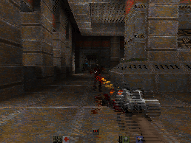
WinQuake, demonstrating the crosshair bug and excessive stereo separation of the weapon
The most obvious problems in the above screenshot are the migratory crosshair (appearing 25% of the way down the screen instead of vertically centred) and the excessive stereo separation of the player's weapon.
If the console variable LCD_X is non-zero, Quake halves the viewport height then doubles what it thinks is the stride of the graphics buffer. This causes it to skip every other scanline when rendering. Instead of rendering once, as normal, it translates the camera in one direction, renders, then offsets the start of the graphics buffer by one scanline, translates the camera in the other direction then renders again. This results in the two views (one for each eye) being interleaved into a single image.
The crosshair is added after the 3D view is rendered (in fact, Quake just prints a '+' sign in the middle of the screen using its text routines), which explains its incorrect position – Quake doesn't take the previously halved height of the display into consideration, causing the crosshair to be drawn with a vertical position of half of half the height of the screen. That's pretty easy to fix – if LCD_X is non-zero, multiply all previously halved heights and Y offsets by two before rendering the crosshair to compensate.
WinQuake, demonstrating the DirectDraw corruption bug
A slightly more serious bug is illustrated above. When using the DirectDraw renderer (the default in full-screen mode), the display is corrupted. This can be fixed by passing -dibonly to the engine, but it would be nice to fix it.
After a bit of digging, it appeared that the vid structure, which stores fields such as the address of the graphics buffer and its stride, was being modified between calls to the renderer. It seemed to be reverting to the actual properties of the graphics buffer (i.e. it pointed to the top of the buffer and stored the correct stride of the image, not the doubled one). Further digging identified VID_LockBuffer() as the culprit; this does nothing if you're using the dib rendering mode, but locks the buffer and updates the vid structure in other access modes. Fortunately, you can call this function as many times as you like (as long as you call VID_UnlockBuffer() a corresponding number of times) – it only locks the surface and updates vid the first time you call it. By surrounding the entire 3D rendering routine in a VID_LockBuffer()…VID_UnlockBuffer() pair, vid is left well alone, and Quake renders correctly in full-screen once again.
The final issue was the extreme stereo separation of the player weapon, caused by its proximity to the camera – it does make the game quite uncomfortable to play. The game moves the camera and weapon to the player's position, then applies some simple transformations to implement view/weapon bobbing, before rendering anything. Applying the same camera offset and rotation to the player weapon as the camera when generating the two 3D views put the weapon slap bang in the middle of the screen, as it would appear in regular "2D" Quake. This gives it the impression of a carboard cutout, and can put it behind/"inside" walls and floors when you walk up to them; I've added a console variable, LCD_VIEWMODEL_SCALE, that can be used to interpolate between the default 3D WinQuake view (value: 1) and the cardboard cutout view (value: 0).
WinQuake with the 3D fixes applied
You can download the replacement WinQuake from here – you can just overwrite any existing executable. (You will also need the VC++ 2008 SP1 runtimes, if you do not already have them). Source code is included, and should build in VC++ 2008 SP1 (MASM only appears to be included in SP1, which is required to compile Quake's extensive collection of assembly source files).
If you don't have a copy of Quake, I recorded its looping demos in 3D and uploaded them to YouTube. This was before I made the above fixes, so there's no crosshair or player weapon model in the videos – if you have access to YouTube-compatible 3D glasses or crossable eyes, click here. 