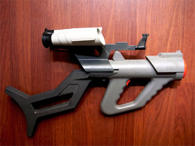
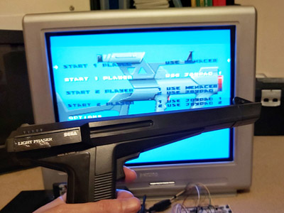
The completed Light Phaser to Menacer adaptor
Friday, 10th April 2020
In the last post I was having difficulty with the overall logic for handling the light sensor signal from the Sega Light Phaser and passing that along to the Mega Drive as if it was coming from the Menacer receiver. This involves latching the signal (instead of passing it along directly) and allowing the console to reset it once handled via the TR line. The signal needs to be delayed as well to simulate the delay from the overhead of the Menacer's wireless communications; without this delay the aiming is offset to the left. The signal is also gated using the TL line; I'm not entirely sure why this is done (some form of external interrupt inhibition?) but it's part of the original receiver so I thought it best to implement this for the sake of compatibility.
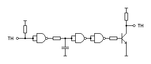
My main problem was that the CMOS NOR chip I had to hand was not triggering reliably with the signal from the light gun and the RC circuit used to delay that signal; I'd swapped it for a TTL NAND chip which then did work however the logic inputs to the latch were inverted (a simple NOR latch has active-high inputs and a simple NAND latch has active-low inputs) and to fix this would have required a lot of additional logic gates. I ordered an SN74ALS02AN TTL NOR chip and found that this worked very well, so have settled on the following circuit:
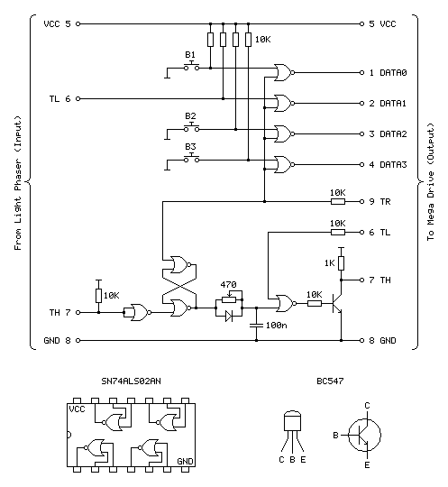
Update (20/04/2020): Please see this post for an updated diagram with a protective 470Ω resistor on the TH output
The four NOR gates towards the top of the circuit diagram are used to gate and invert the inputs from the four input buttons (one main trigger on the Light Phaser and three secondary function buttons on the adaptor itself). This is unchanged from the previous circuit and still works well.
The most important aspect of the circuit at the bottom of the diagram between the two TH pins is the latch made of two crossed-over NOR gates with the output from one going to the input of the other and vice-versa. The two inputs to this latch are normally low (TR from the console is driven directly and normally low, TH from the Light Phaser is normally high but inverted by a NOR gate with its legs tied together). When the reset pin TR goes high the output of the top gate must go low, as a NOR gate will always output low if either (or both) of its inputs are high:
| Inputs | Output | |
|---|---|---|
| A | B | Q = A+B |
| 0 | 0 | 1 |
| 0 | 1 | 0 |
| 1 | 0 | 0 |
| 1 | 1 | 0 |
If we assume that the other input to the lower NOR gate is also in its default low state then the two low inputs will result in a high output. This high input travels back to the top NOR gate's other input. This means that even when the TR pin goes back low again there is still a high input on that top NOR gate and so it maintains its low output.
When the Light Phaser sees light its TH output goes low, the NOR gate with its legs tied together inverts this to go high and the bottom input to the lower NOR gate in the latch goes high. This makes its output go low, which travels to the top NOR gate, making both inputs low (assuming TR is still low) and making the top NOR gate output a high which comes back down to the lower NOR gate so that even when the Light Phaser stops seeing light and the other input to the bottom NOR goes back to low there is still a high on the other pin, keeping the overall output low.
Effectively, what this means is that when the Light Phaser sees light the output of the latch goes low, and to return this back to a high the console needs to pulse the TR pin high.
The output of the latch goes to a delay circuit consisting of a resistor, capacitor and diode. This delay is required because the real Menacer introduces a delay between when it sees light and when it triggers the console's TH pin, and games are programmed to compensate for this. Without replicating this delay the aim is offset considerably to the left.
The logic gates are digital devices however still adhere to analogue rules and will treat certain voltages as high or low digital signals when they pass a certain threshold. The delay is implemented by slowing the rise or fall of the logic signal by charging a capacitor via a resistor, so whilst the logic signal at the output of the latch changes very quickly it will take the capacitor a while to charge or discharge via that resistor to a voltage level that is interpreted as a change of state by the following logic gate. The diode is there because we want the signal to be delayed when the gun sees light (when the logic level goes from high to low) but want it to change quickly when the latch is reset (going from low back to high again). When going from low to high there is a higher voltage to the left of the diode than there is across the capacitor to its right and so current can flow quickly through the diode, bypassing the slow resistor and charging up the capacitor quickly. When going from high to low the current can't flow backwards through the diode and so the capacitor has to discharge slowly through the resistor, providing the desired delay.
After this delay comes another NOR gate with its other input coming from the console's TL pin. I'm not entirely sure what this is for, as mentioned above, but it does at least allow us to buffer the signal from the RC delay circuit. The real receiver circuit then uses a final NOR gate with its inputs tied together to invert the latched signal before passing it to the console via a 470Ω resistor, but as I am already using an extra NOR gate to invert the input from the Light Phaser and have therefore used all four gates on one chip I instead use a transistor with a 1K pullup to invert the signal. The Light Phaser uses such a transistor circuit with the same 1K pullup resistor on its TH output so I thought it safe to use it here as it would be electrically compatible. The real receiver also includes 10K series resistors on its inputs from the TR and TL lines – I'm not entirely sure why but in case there was a good reason I thought I should use them here also!
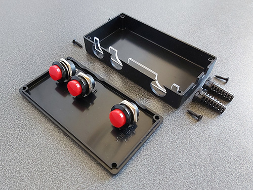
With the circuit appearing to work well I thought it was time to put it in an enclosure. I found a box that was a comfortable size to hold in one hand – it's about the same overall size of a Master System control pad other than being quite a bit fatter. This allowed me to put the three push buttons down the side of the box so they can all be pressed easily when gripping the box in one hand. The lid of the box has a lip that would interefere with the ability to tighten the nuts for the buttons and so I cut a small piece of acrylic that is slightly thicker than the lip and short enough that the box can be closed with it in place.
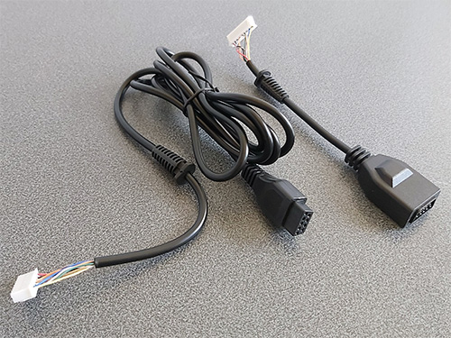
Of course, we need something to plug the Light Phaser into and a cable to plug the adaptor into the console with. A good source for these connectors is an inexpensive extension cable, so I bought one and cut it in two so I could use it for this project. After cutting the cable in two I installed strain reliefs and crimp connectors, and definitely remember to do that in that order! Interestingly I've bought a few of these cables recently from different suppliers (and with different moulding designs for the console plug and controller socket) and they've always been about half the length advertised but sold in packs of two.
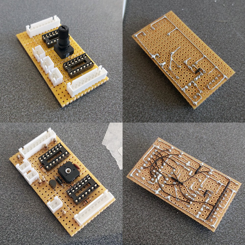
I normally use pad board to solder my final circuits together. I start by roughly placing the components on the board where I think they should end up going, and when I've got the main parts in place I flip the board over and start soldering them down, using bare pieces of wire to make connections between components. I lay the bare pieces of wire as straight as possible and try to avoid crossing them over; where necessary I'll add a piece of insulation to a wire where it needs to cross another. Once as much of the board is placed in that fashion I'll solder thin wires between the points that can't have direct connections. It may not be the prettiest job (and making corrections afterwards is a bit of a pain) but it's worked well for me and I've found it allows for more compact layouts than stripboard.
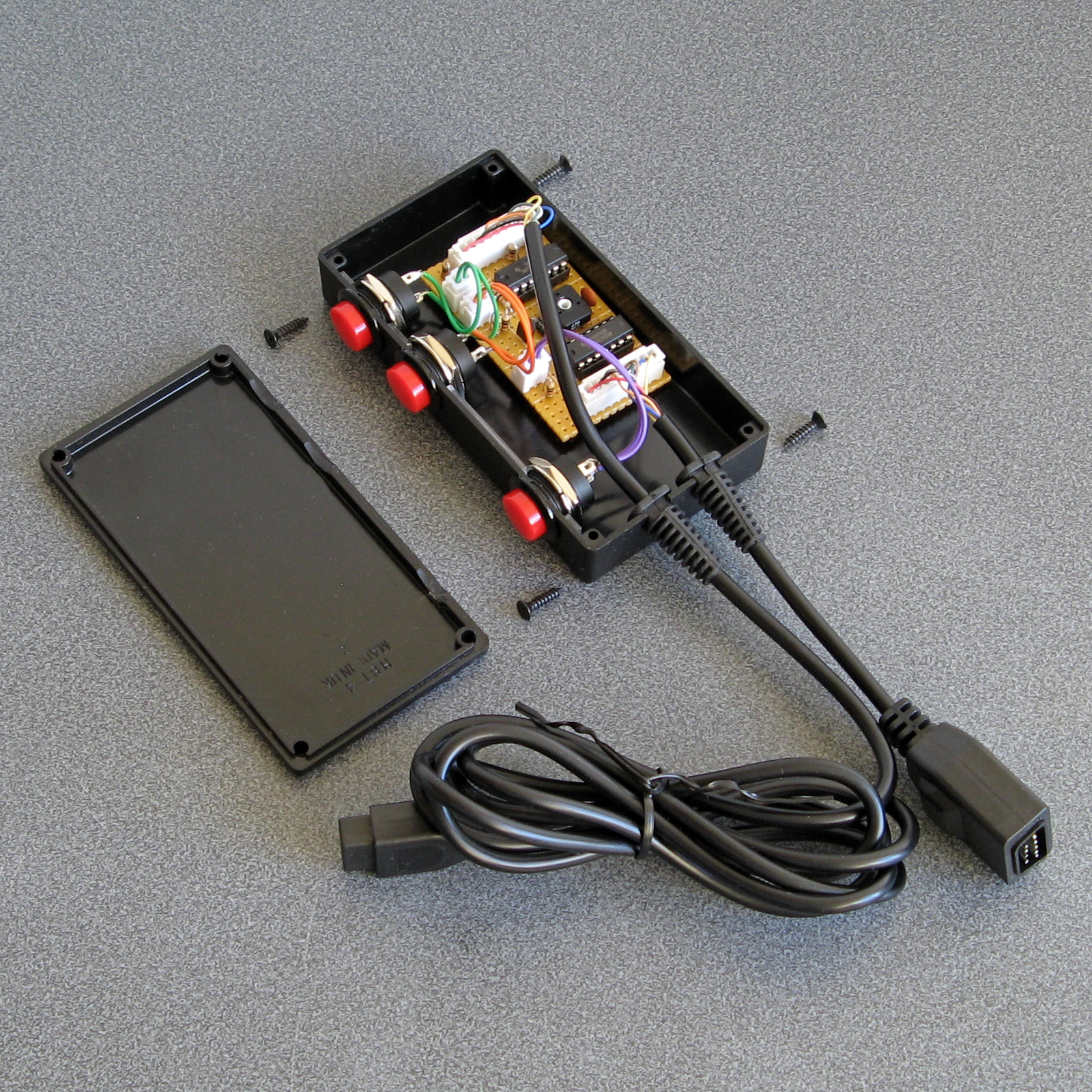
Some crimp connectors were then added to the three push buttons and the whole circuit was installed in the box. Before the lid was screwed down the delay to correct the horizontal aim was calibrated using the 470Ω variable resistor. To adjust it the variable resistor was first set to its smallest resistance value and the tip of the light gun was touched to the centre of the screen. The aiming reticle is quite far to the left by default so the resistance of the variable resistor was then gradually increased to move the aiming reticle in the game right until it sits under the tip of the gun. The aim was then checked at the extreme left and right sides of the screen and if there were any dead zones the variable resistor was adjusted to move the aiming reticle away from the edge of the screen until it had a good range of motion across the entire width of the screen.
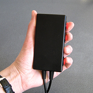
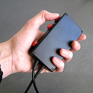
The two different grip styles for the adaptor buttons
The adaptor can be gripped in two different ways – in the regular position you have direct access to all three extra buttons with your fingers, and in the reversed position you have access to a single button at a time with your thumb. None of the games I've played on the Mega Drive use more than two extra buttons (and usually one of those is the bottom "Pause" button) but it's always good to have options!
I have tested the adaptor with the three Mega Drive games that support the Menacer — the six-in-one pack-in cartridge, T2: The Arcade Game and Body Count and am happy to report that it works with all three. I am not going to be able to test it with any Mega CD games as I do not have a Mega CD or a compatible flash cartridge, I'm afraid to say, but hopefully it will work just as well with those games.
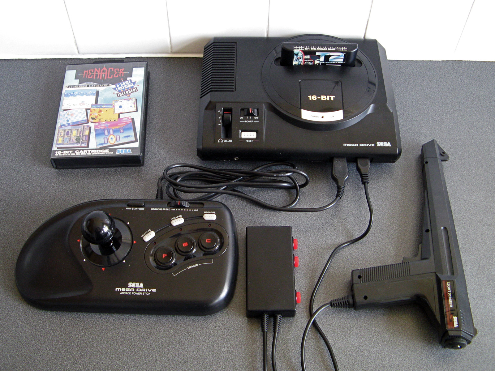
The red and black theme was chosen to match the other accessories and I think it fits in rather well, even if it is a bit boxy-looking. If you are reading this and build the circuit yourself I'd love to hear how you get on!
Fixing the Menacer detection but breaking the accuracy of the aim tracking
Thursday, 26th March 2020
Since the last post about my experiments with using a Sega Light Phaser to play Mega Drive games I've had some good results and some disappointing ones that I'm still trying to work through.
The easy problem to solve was the handling of the buttons and making sure that the gun continued to be detected as a Menacer whenever a button was pressed. The previous circuit used active-high buttons (including an inverter to convert the active-low trigger from the Light Phaser into active-high signal) gated using the console's TH line via an AND gate. This meant that each button output a 0 when not pressed and 1 when pressed when TH was high, or a 0 in all cases whether TH was low or high.
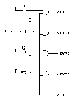
When looking at the patent for the Menacer it became apparent that the button data lines were coming from a four-bit counter that is reset by the console's TR pin going high. When looking at logic analyser traces from T2: The Arcade Game we can see that TR is held high during device detection at the main menu screen but goes low during gameplay, being periodically pulsed high when the game alternates between handling light detection (short pulse) and reading button presses (long pulse). Rather than active-high buttons with AND gates, active-low buttons with NOR gates would seem to work better, so I ordered some NOR gate chips and tried the following circuit:
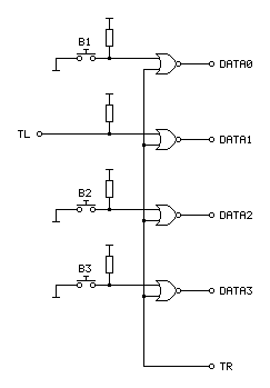
In the diagram above the TL on the left comes from the Light Phaser and the connections on the right go to the Mega Drive.
An OR gate will output a 1 if either of its inputs is a 1, to output a 0 both inputs have to be 0. A NOR gate inverts this output, so will output a 0 if either of the inputs is a 1 and will only output a 1 if both inputs are 0. When TR from the console is 1 it therefore forces the output to always be a 0, however if TR goes low to a 0 then the output is 0 if a button is released and 1 if a button is pressed – just what we needed.
Testing with T2: The Arcade Game I found that all of the buttons still worked during gameplay, and when pressing a button at the main menu the gun continued to be detected as a Menacer unlike the previous buggy implementation. All good so far!
I wanted to test with some other games, so ended up buying a copy of the six game cartridge that was originally bundled with the Menacer. I paid a little bit more and got a copy that came with the IR receiver, which is not much use without the gun however I thought it still might provider some interesting clues as to how to convert the signals from the Light Phaser to the Menacer protocol more correctly.
When the cartridge arrived I plopped it into my Mega Drive and was happy to see that the games mostly worked fine without any further tweaking. There was one fly in the ointment, however, an occasional message about the screen being too dark:
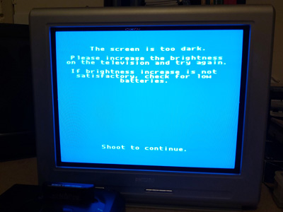
"The screen is too dark".
It would only do this occasionally when launching one of the six games and would then reset to the main intro and menu screen after shooting. Oddly, once a game was started I could quite happily move away from the TV to the other side of the room and the gun still worked reliably, so I'm not sure if this genuinely is an issue with the screen being too dark or if it's some problem with the way the gun is triggering the TH line on the console to indicate when it's seen light.
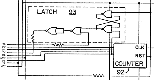
To try to get to the bottom of the issue I took apart the Menacer receiver and started sketching a circuit diagram based on the counter and NOR gate chips on the board. I then compared my scribbles to the circuit diagram in the patent, and found that the final implementation does appear to match the diagram in the patent pretty much exactly (I can't tell for certain as quite a lot of the circuitry is enclosed in a metal can, but all of the circuitry relating to the counter and NOR gate latch matches). This meant I was able to match up the console's pin connections to the diagram, which are unlabelled in the patent:
Pin connections for the Menacer receiver
It's not particularly clear due to how closely-packed the connections are in the diagram, however the important details are as follows:
- D0~D3 are connected to the counter directly, with D3 also going to set the latch at the top.
- TR resets the counter and the latch.
- TL appears to inhibit the output of the latch.
- TH only needs a 470Ω resistor between the output of the latch and the input to the console, not a common-emitter transistor driver.
I thought it would be neat if I could combine the function of the latch and the counter, so purchased a CD4017B decade counter chip as this has a handy clock inhibition input and wired it up as follows:
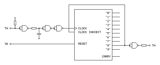
The clock input to this circuit comes from the TH output of the Light Phaser gun. This is an active-low signal so it needs to be inverted to properly clock the counter chip on the rising edge of the signal. It also needs to be delayed slightly for proper horizontal aiming (described in the previous post) so hence the additional RC circuit before the signal is fed to the counter chip.
With such a decade counter one of the 10 outputs labelled "0" to "9" is active at a time. After resetting the chip (by pulsing the reset pin high) "0" is high and "1" to "9" are low. When there is a rising edge at the clock input the chip counts up, so "0" goes low and "1" goes high, then "1" goes low and "2" goes high and so on and so forth. The "carry" output provides a rising edge clock signal when the counter overflows from "9" back to "0", allowing multiple chips to be chained together.
In the Menacer receiver the counter triggers the TH output latch on the fourth bit of a binary counter, i.e. when it reaches 8, so I've used the output of "8" as the output of the circuit. I've also fed this output back to the "clock inhibit" input of the counter chip. When this pin is low (which "8" will be when the counter is reset) it allows the counter to count up normally whenever the clock pin is pulsed. When the pin goes high (which "8" will be when we've seen eight pulses of light from the gun) it will inhibit the counter from counting any further, effectively locking it at "8". The only way out of this condition is to reset the chip, which the console does by pulsing the TR input line.
The only additional complication is that the console still expects an active low signal from the gun, so the final step is to invert the output from the counter.
Unfortunately, this does not work at all well. Games no longer seem to produce the "The screen is too dark" message, however aiming is extremely laggy and inaccurate. Checking the output of the counter with a logic probe seems to indicate erratic triggering. Using a different output from the counter (e.g. "4" or even "1") so that the counter "latches" sooner seems to improve things slightly but overall performance is still far worse in this arrangement. I'm not entirely sure why!
My next attempt was to simplify matters by using the exact latch circuit composed of NOR gates described in the patent, which worked just about as badly – the circuit still triggered eratically and accuracy was very poor. I have had issues with circuits not triggering properly before when using particular logic chips (it's why the circuit for my LCD Shutter Glasses adaptor has SN74LS14N Schmitt-trigger invertors on the logic inputs) so I thought I'd try replacing the CD4001B CMOS NOR gate chip I was using with the SN74ALS00AN TTL NAND gate chip I was using in previous experiments. The logic for a latch built from NAND gates is inverted to the logic of one built from NOR gates so it wasn't a straight swap but I don't have any other NOR gates in my parts bin. Somewhat surprisingly, with this new chip performance was greatly improved, though still not quite right.
For my next set of experiments I'm going to try replacing the CMOS NOR gate with the TTL NOR equivalent, though as that will involve waiting for parts to turn up in the post I thought I'd write a quick update on where I am so far. Fingers crossed this issue can be resolved easily and with a simple circuit!
Using a Master System Light Phaser in Mega Drive Menacer games
Wednesday, 18th March 2020
I'm a big fan of light gun games and have guns and games for most of the Sega systems – the Master System's Light Phaser, the Saturn's Virtua Gun and the Dreamcast's gun all get plenty of use.
One notable omission is the Sega Mega Drive and its Menacer light gun. This is a wireless gun with a range of bulky plastic accoutrements that represented Sega's efforts in the 16-bit generation; unfortunately only three games were released for it on the Mega Drive – a six-in-one collection of minigames that came bundled with the gun, a port of T2: The Arcade Game and the ferociously-expensive Body Count.
Ultimately the gun was a flop and they are not cheap to pick up second-hand (and are often missing most of the bits) so I haven't sought one out, however I did recently buy a cheap job lot of games which included a loose copy of T2: The Arcade Game.
I tried the game with the regular control pad and found it a disappointing experience (as most light games are when played with a pad!) so thought I'd see if I could get it to work with one of my Master System Light Phaser guns.
Of course, the game wouldn't detect that the gun was plugged in. Controllers on the Master System were generally very simple affairs, with one pin on the controller port per button (no multiplexing or serial data transfers here). On the regular control pad four data lines were used for the d-pad directions and two data lines (TL and TR) were used for the two buttons. These data lines were pulled high by the console and the control pad just contained switches that connected these data lines to ground when pressed for simple active-low logic.
The Light Phaser doesn't make use of the four d-pad data lines and only has one button so only uses one of those two data lines (TL) however it does make use of another pin on the controller (TH) for its light sensor. When this pin goes low the console latches the video chip's horizontal counter and the game software can read this and the free-running vertical counter to determine what point on the screen the console was outputting at the point the gun "saw" the light from the TV (and from this work out where the gun is aiming).
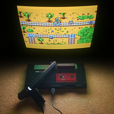
The Sega Light Phaser being used to play Rescue Mission on the Master System.
The Mega Drive is descended from the Master System's design and has very similar controller ports. The d-pad's four data lines are named DATA0 to DATA3, and by default the B and C buttons are mapped to the two TL and TR inputs like the two buttons on the Master System controller. However, the Mega Drive controller adds two extra buttons (A and Start). These two extra buttons share the TL and TR data lines and whether they are B and C or A and Start depends on the state of the TH line which is configured as an output from the console.
This use of the TH line to choose which buttons are mapped to which data lines is also used for controller identification. When TH is high the d-pad is mapped to the four data bits as normal. However, with a normal controller, when TH goes low data lines 2 and 3 (corresponding to left and right) go low also. This is normally impossible, as you can't physically press left and right simultaneously on a Master System controller, so a controller that ignores the state of the TH line won't be detected as a Mega Drive controller.
The device ID is encoded as a four-bit value according to the following logic:
| ID bit | TH state | Data bits |
|---|---|---|
| 3 | High | 3 OR 2 |
| 2 | High | 1 OR 0 |
| 1 | Low | 3 OR 2 |
| 0 | Low | 1 OR 0 |
For example, to read a regular controller's ID set TH to high and read the data lines. In this state the d-pad is mapped to the data lines. Bits 3 and 2 are mapped to to right and left. If neither is pressed both bits will be "1" as the inputs are active-low; 1 OR 1 is 1. If either left or right is pressed then one of the bits will be "0" but the other will be "1"; 0 OR 1 is also 1. The only way to get a zero is if both directions are pressed simultaneously which is not possible, so ID bit 3 will always be 1.
The same applies to ID bit 2, as this is uses data lines 1 and 0 which are mapped to the down and up buttons, so this will also always be a 1.
After setting TH low, we know that data lines 3 and 2 are forced to 0 so ID bit 1 is a 0.
Finally, ID bit 0 is based on data lines 1 and 0 which are still mapped to down and up and so will still be a 1. This all gives us a device ID of %1101, which is indeed the peripheral ID of a standard Mega Drive controller.
This is fine, but what does it mean for the Menacer? Well, that device has an ID of %0000. For this to happen we need to make sure that all four data lines are low whenever the console is reading the device ID. The easy way to do this is to take apart a Master System controller and to press all four d-pad buttons down simultaneously – doing so and starting the console with the T2 cartridge inserted makes the game think that a Menacer is plugged in!
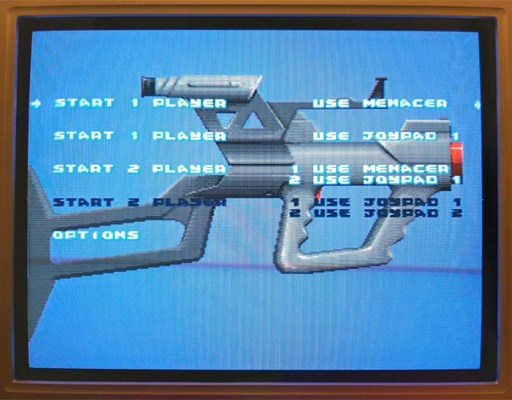
The Use Menacer options are white and selectable.
Somewhat unusually the Menacer's four buttons are mapped to the four data lines (instead of TL/TR) and are active high which means that if I start the game and let go of one of the Master System controller's buttons then it thinks I've pressed one of the Menacer's buttons (for example, releasing the "down" button makes DATA1 go high and the game thinks I'm pulling the trigger). Of course, I can't aim in this mode as there's no light gun input but it's good to see something is working!
I assumed that if TH is normally used for device identification I would start experimenting with using that to determine when the adaptor should output all zeroes. Considering the buttons need to be inverted to active-high logic too I thought it best to use an AND gate on each button so that if TH is high (normal state) the button input would pass through to the data line, but if TH is low (detection state) the data line would be forced low. I wired this up with an AND gate and four push buttons and the game still detected a Menacer and pressing a button in-game would now fire the weapon. Seeing that this worked, I removed one of the four push buttons that was previously used for the trigger button and used the TL data line from the Light Phaser instead via an inverter:
In the diagram above the TL on the left comes from the Light Phaser and the connections on the right go to the Mega Drive.
I assumed that the Menacer would also use the console's TH input for the light sensor from the gun (similar to the Light Phaser) so tried wiring up the Light Phaser's TH output to the Mega Drive's TH input. Moving the gun around the screen moved the aiming cursor around. Unfortunately, the aim was pretty far off:
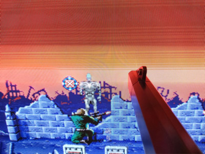
The blue cursor should be under the gun, which is touching the screen.
The game placed the aiming cursor a consistent distance left of where the gun really was aiming. I assumed this was due to the game expecting a delay between when the gun saw the light from the screen and it sending a pulse to the console – unlike a wired gun that can send the signal back to the console very quickly the wireless Menacer converts the detected light pulse into an IR pulse that then needs to be handled by the receiving unit plugged into the console. By the time the console sees this pulse it will have moved further along the current scanline (right), so the game software works backwards (left) to an earlier point on the scanline. As I'm using a wired gun that transmits the signal much more quickly this left offset causes the aim to be incorrect.
The solution to this is to introduce our own delay into the signal, which I did with a crude RC circuit:
As I'd previously used a NAND chip to invert the signal from the trigger button I used three more of its gates to implement the delay. The first gate buffers the signal as the gun's TH is a common emitter output, so either connected to ground or pulled high via a resistor. This buffered signal then charges or discharges a capacitor to ground via a resistor – this provides most of the delay, and in my testing a 220Ω resistor and 100nF capacitor provided better aim. The next two gates buffer the signal again before driving a transistor for a common emitter output – as the console is also driving the TH line as an output I didn't want to directly drive it from the adaptor circuit and so the transistor seemed safer and is how the Light Phaser works anyway.
This is a crude circuit and has its limitations (very short pulses could be dropped entirely rather than delayed, for example) but it does at least seem to greatly improve the aim:

The cursor now lines up with the point on the screen the gun is touching.
The game is now fairly playable, though there is one notable flaw with the circuit: pressing any button at the main menu screen causes the game to assume the gun has been disconnected, disabling the Menacer options:
The Use Menacer options are dark and no longer selectable.
Clearly using the TH signal alone to disable the buttons is insufficient, we must need to also output 0 when TH is high for full compatibility with the peripheral ID reading and the gun must use some other technique to enable or disable the button data.
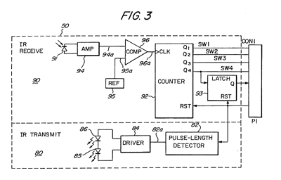
Fortunately, a copy of the Menacer patent can be downloaded from the Sega Retro website where it can be studied to see if it provides any more clues for how the Menacer works. It goes into some detail about how the gun communicates with the console, including this figure showing the gun:
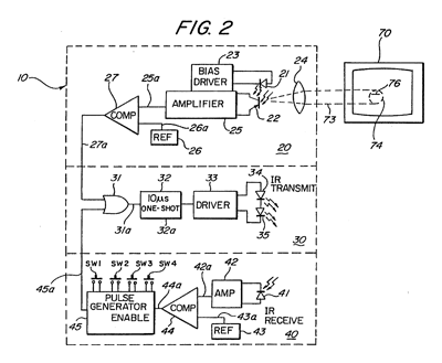
The centre portion of the image shows that infra-red signals from the gun are transmitted to the receiver in the form of 10µs pulses. The top portion of the image shows that these pulses can be generated by the gun's light sensor, so whenever the gun sees light it will send a 10µs IR pulse to the receiver. The bottom portion of the image shows the pulse generator used to encode the button presses; the button state is interpreted as a binary number and a corresponding number of IR pulses are sent: if SW1 is pressed then 1 pulse is sent, if SW2 is pressed then 2 pulses are sent, if SW3 is pressed then 4 pulses are sent and if SW4 is pressed then 8 pulses are sent. If multiple buttons are pressed then their values are added, so if SW1 (1) and SW3 (4) were pressed then five pulses would be sent up to a maximum of 15 pulses for all four buttons being pressed.
These button press pulses are only sent back to the console receiver after the gun receives an IR pulse from the receiver.
The receiver uses a counter chip to convert the IR pulses from the gun into button press or detected light pulses for the console. The duration of reset pulses are important here. The patent describes a standard counter reset pulse as being 2-3µs long and a main reset signal pulse as being about 10µs long. Any short reset pulse will reset the counter chip and latch. A long reset pulse will stil reset them, but also trigger a pulse of IR via the transmitter section at the bottom of the diagram. This IR pulse will cause the gun to send its button data back to the receiver, where the pulses will be counted by the counter chip and drive the DATA0 to DATA3 pins. After a certain delay to ensure that all button states have been sent the game software can read the button state and reset the counter, ready to read pulses from the light sensor in the gun. Bear in mind that the button state will have to be read before the active display starts, as the gun always sends an IR pulse when it sees light and this will cause the button presses to be miscounted.
Rather than pass every single detected pulse of light from the gun to the console it looks like the counter is used to detect eight pulses, after which it triggers a latch. This appears to be due to the assumption that when the gun is an expected distance away from the TV it will trigger on around 20 scanlines, and so by waiting for eight it will place the detected position roughly in the middle of those 20 lines.
All in all, this is a simple enough system but what does it mean for our convertor circuit? Will we need to add extra pulse length detectors and counters to make sure we send through the right sort of data?
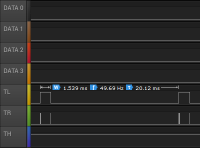
I captured the state of the controller port lines during gameplay and found the above logic traces. Each frame TL goes high briefly and is then low for the active part of the frame. Pin TR has very brief pulses, and these appear to be the reset pulses. If we zoom in, we can see these more clearly:
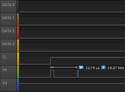
Here TR goes high for over 10µs and so must be the main reset pulse (used to read the button state) and the next pulse is around 3µs and so must be the regular counter reset pulse. The gap between these pulses is only 85µs, however – if the button IR pulses are 10µs long then this would not give us enough time to read them – even if there was no gap between them 15 pulses of 10µs would take 150µs. Either there is a delay of at least 85µs before the gun starts sending the button data or the timing is different in the real gun when compared to the patent information. There is a final 3µs reset pulse as TL falls and this pulse comes 1.435ms after the previous short reset pulse so that would provide plenty of time to receive the button press data before resetting the counter ready to detect light pulses.
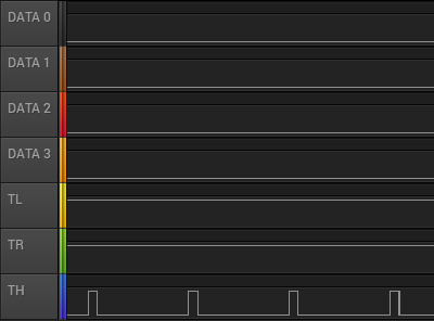
The next bit of the puzzle is what happens during the main menu when the Menacer is being detected. The traces are shown above. Both TL and TR are fixed high during this process. If we assume TR alone is used to reset the counters then holding this high would fix the data lines at %0000, identifying the controller as a Menacer. The TH line is also being pulsed here, possibly as the code is still checking to see if it could be some other type of controller.
If we force the output of the data lines to be 0 when TR is high (acting as a reset) then maybe this would work more reliably (and correctly) than when TH is low. I'll need to perform some further experiments, and also see whether the lack of the eight scanline delay before triggering the TH line to indicate detected light causes any other problems. I like the idea of a simple device that only uses logic chips to adapt the gun but if we need a more sophisticated circuit to time reset pulses and offset the vertical position maybe it would be better to switch to a microcontroller circuit. If that was the case, maybe the adaptor could also be programmed to work with games that use the Konami Justifier, another Mega Drive light gun that is incompatible with the Menacer.
If you'd like to see the circuit in action, I've uploaded a quick video on YouTube to accompany this post.
Repairing damaged plastic pegs
Friday, 4th October 2019
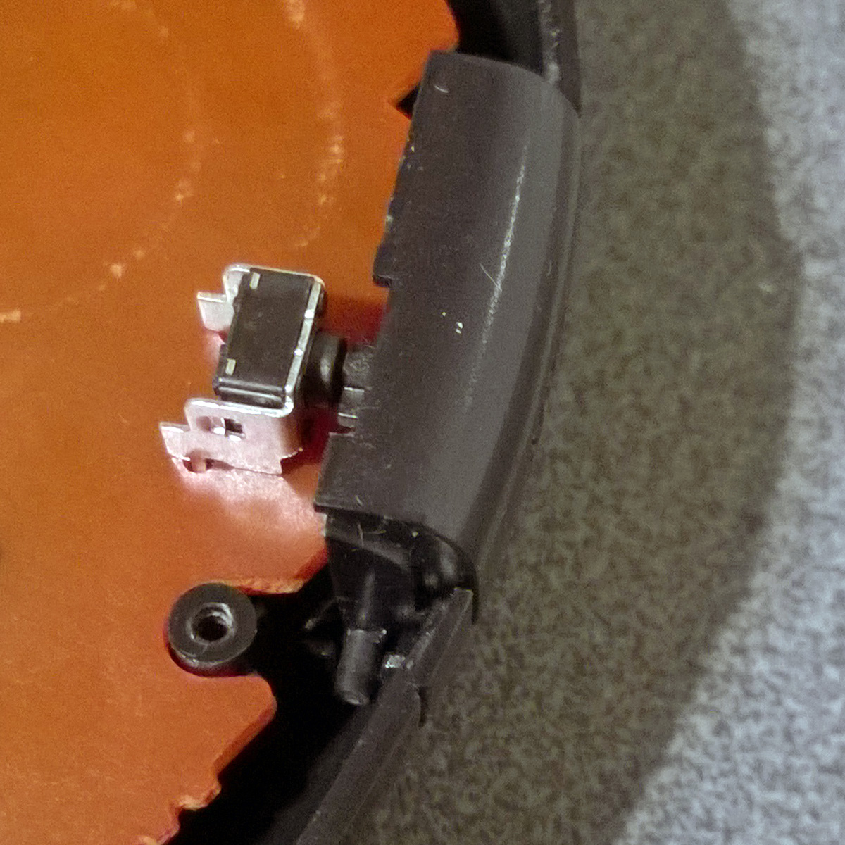
It's not uncommon for parts of old electronic devices to have damaged plastic pegs, like the one in this photo:
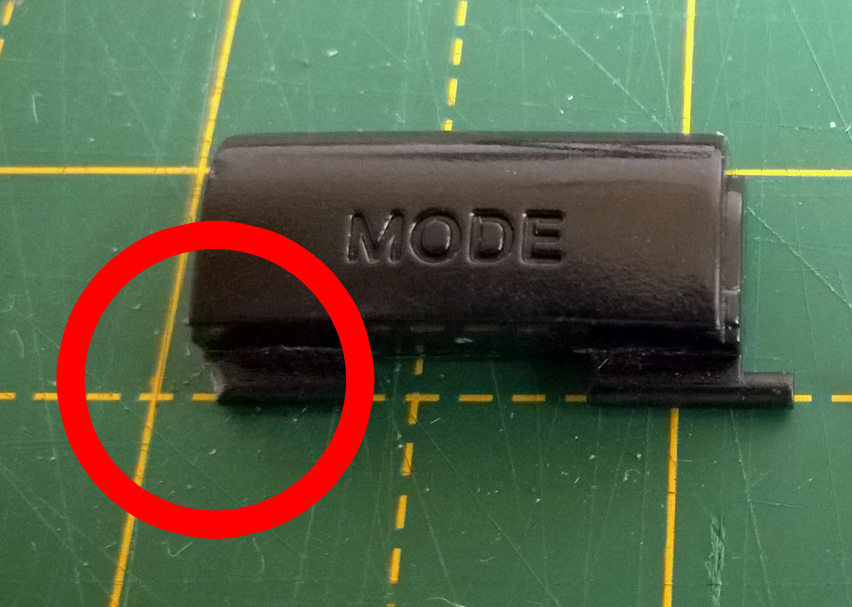
If you still have the snapped off plastic peg you may be able to glue it back on, but this can leave a weakened part that doesn't hold up very well. In other cases you might have lost the part entirely. This happened to me recently with the purchase of a six-button Mega Drive control pad. I ordered it from CeX's website and so couldn't see what condition it would be in until it arrived in the post. Unfortunately, it arrived in a filthy condition with a d-pad that only worked if you pressed the buttons very firmly and a non-functioning Mode button. I took it apart and was able to get the d-pad working again by cleaning the contacts. Whilst I left the rest of the plastic parts soaking in the sink to try to remove as much of the encrusted grime as possible I turned my attention to the faulty Mode button.
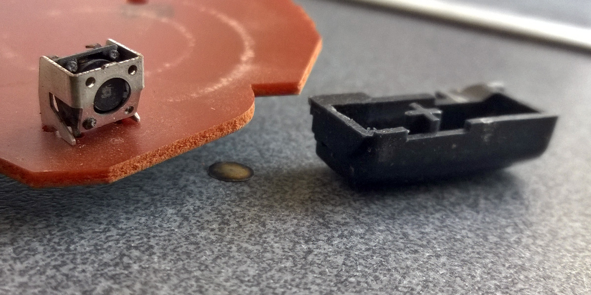
At some point the button must have been pushed in too firmly, damaging the tactile switch on the main board - the metal casing was bent and the plastic switch body had separated from it with the metal diaphragm that closes the contacts falling out. I've seen the same thing happen to some Sega Saturn control pads and fortunately had some spares in my parts bin so was able to swap that out easily. However, the pressure had snapped one of the plastic pegs of the Mode button off and it was nowhere to be found, so I needed to construct a replacement.
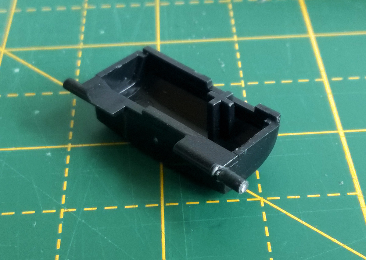
Fortunately, I have some scrap plastic parts from cutting out holes in plastic enclosures. In my case I needed to make a new peg that was 1.8mm in diameter, and had some 2mm sheet to use for this purpose. If I didn't have this then I could have gone online to buy a small 2mm thick sheet of ABS, but I prefer to recycle where possible!

The first thing to do was to get a piece of plastic that was roughly the right size, so I cut a length with a cross-section of 2×2mm. To cut the plastic I scored it with a knife and then snapped it by gripping the short part with a pair of pliers and bending the longer part away from the score line.
As the plastic peg needs to rotate in its slot inside the control pad it needs a round cross-section rather than a square one. To shape the peg into a rough cylinder I mounted it in the chuck of a rotary tool, as pictured above.
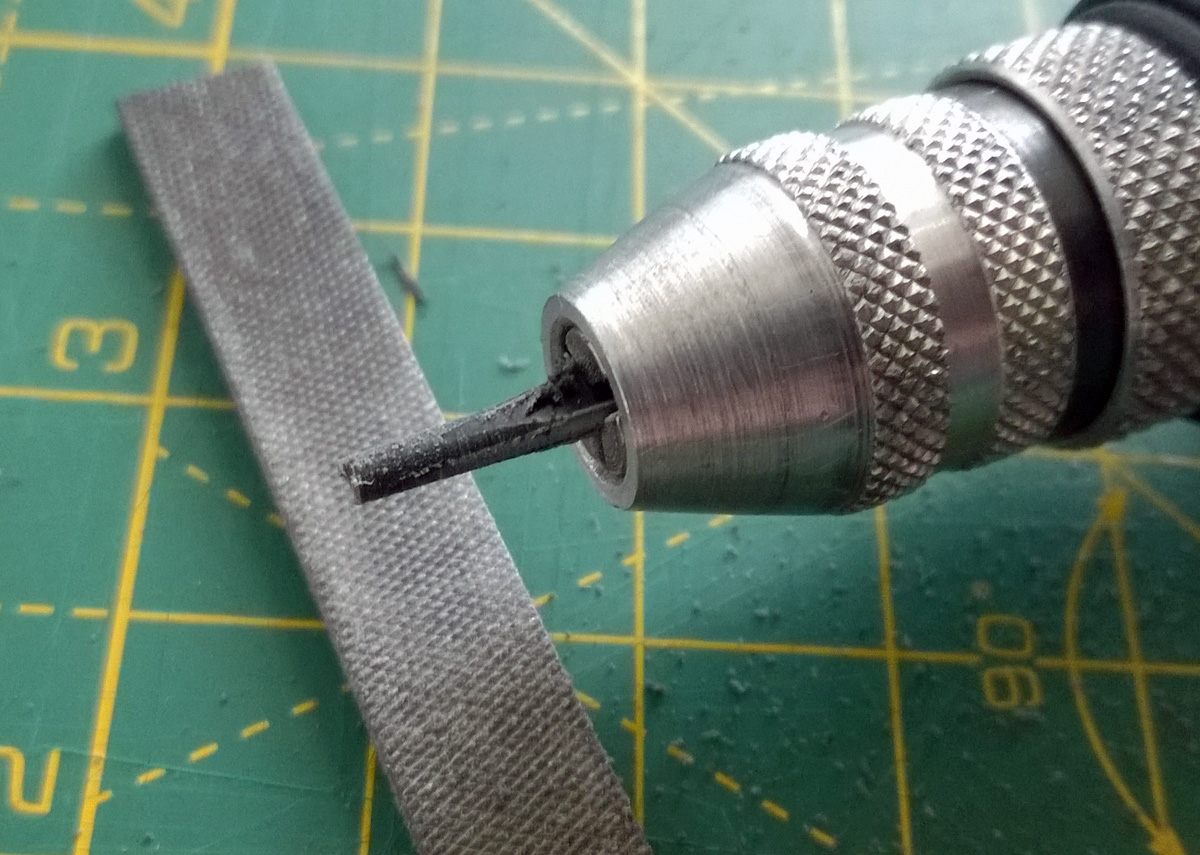
The rotary tool was then switched on and the plastic part held against a file. The photo above shows the start of this process with the peg beginning to take form. You need to work somewhat slowly with plastic as it gets hot when filing, cutting or drilling and if you let the heat build up it can melt and bend or gum up your tools. In my case I only used the file for a short period at a time before giving the piece time to cool back down. If I had been able to use my variable-speed rotary tool I could have set it to a lower speed to reduce the heat however the collet chuck on that tool wouldn't have been able to grip the work piece.
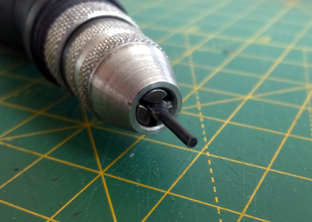
It doesn't take very long to get a nice round profile on the peg, though, even when working slowly (it's only a small piece, after all!) I carried on working it until I measured the 1.8mm diameter I was aiming for.
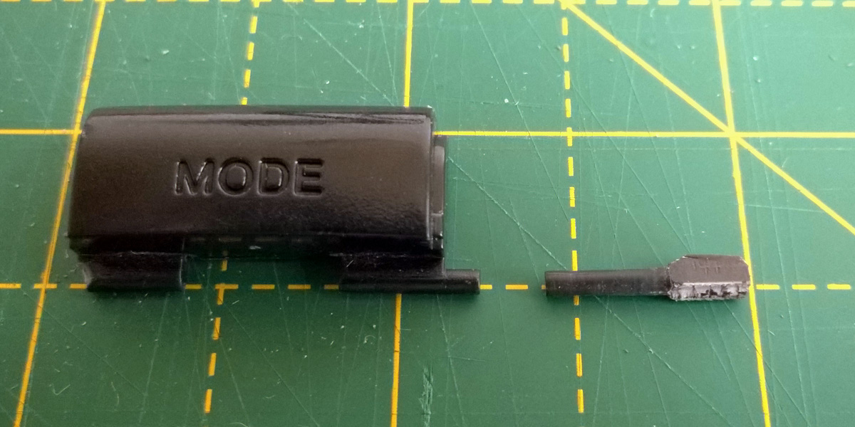
The above photo shows a size comparison between the new peg and the intact one on the Mode button. I've left the piece long (with the rough ending as a "handle") to make it easier to work with until it's time to fix it in place rather than cutting it to length straight away.
How to attach the new peg to the damaged button is the next issue to deal with. The rough surface of the snapped area of the button would make gluing difficult, though it could be filed flat to provide an easier surface to work with. My preferred technique, however, is to fix the new plastic peg with a metal pin made from a paper clip. This involves drilling narrow holes in the old button and the new peg to fit the metal pin through.
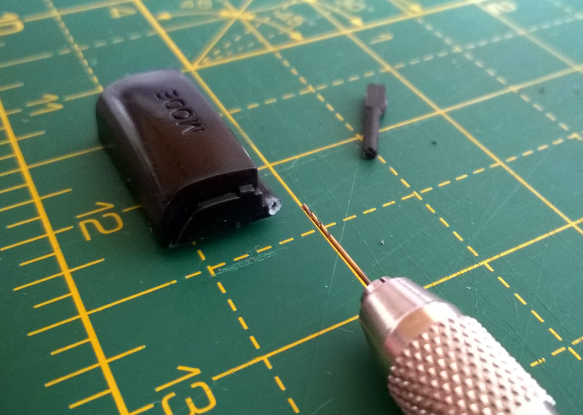
A pin vice is an invaluable tool for fine drilling work like this. I started with a very small drill bit to make the initial hole, being very careful to ensure I was drilling straight and in a well-centred location. This is something that needs to be taken slowly, especially on the original part. Once I had a pilot hole in the right place I switched to a larger drill bit that would drill a hole that the paper clip could fit into.
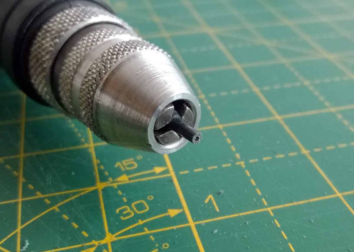
Starting the hole in the plastic peg might be easier by spinning the piece in your rotary tool and then bringing the stationary drill bit up to the end of it. As before be very careful about melting the plastic as once the hole is drilled the plastic is even thinner and will melt more easily – the peg is much shorter in the above photo than it was in previous photos as I accidentally melted it when I tried to drill all the way through in the rotary tool. I had to cut off the melted and distorted part to start again, only starting the hole in the rotary tool this time and then drilling the rest of the way slowly by hand. It's a good thing there was plenty of excess material!
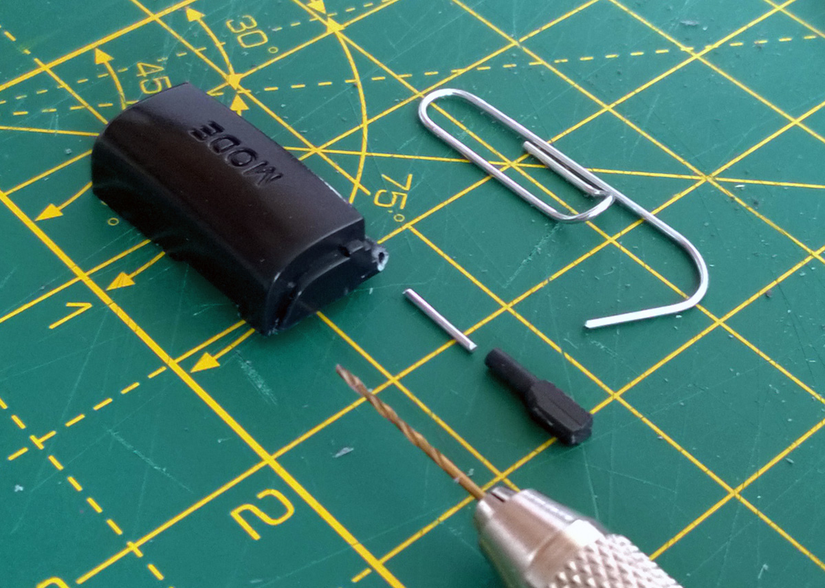
The above photo shows the short length of paper clip that has been cut to connect the two plastic parts. Using a piece of wire like this should provide a lot of strength to the join – my experiences of gluing plastic to plastic have been very mixed, depending on the glue and plastic involved.
The parts in this case are all glued together with superglue and it seems to hold together quite well. The replacement peg was first cut to length before being glued. I coated one end of the paper clip rod in glue before pushing it into the hole on the button, then added glue to the other end and slid the new peg on. The end of the peg had a slightly protruding piece of the paper clip rod, so it was filed flush once the glue had set.
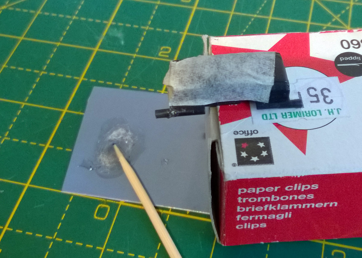
The uneven break still left a small gap in the join between the new peg and the Mode button body, so I filled it with a small amount of two-part epoxy resin. I used a toothpick to transfer a small amount of the mixed epoxy resin into the gap. This is always a bit messy so I protected the main button surface with masking tape. I also tidied up any "blobbiness" or glue that had otherwise run to undesired areas with a sharp knife before the epoxy had fully cured.
The button now sits properly in place inside the control pad and swings freely as it should. I could of course have just returned the control pad for a refund considering its condition but in spite of its problems it was still a well-priced item and I'm not sure they would have bothered to repair it. At least I know this way it'll be appreciated in its second life!
Modifying a Master System cartridge for use with flash ROMs
Thursday, 22nd August 2019
I have a ToToTEK GG-PRO flash cartridge to run homebrew software on my Game Gear however I have never been able to get it to work on my current PC and it seems that it's hard to find a Master System equivalent these days. A contemporary alternative is the Master EverDrive and it is by all accounts an excellent piece of equipment however it is a very expensive product.
I had, however, heard that certain Master System cartridges could be modified to accommodate a flash memory chip in place of their stock mask ROM. I do say certain cartridges as it's the ones with separate mapper chips that need to be used. One such cartridge is After Burner, and as I was able to find an inexpensive loose copy on eBay I used that as the basis of my modifications.
The memory mapper is used to map ROM banks or save RAM on the cartridge into one of three 16KB slots in the Z80's address space. Most Master System cartridges only contain a single chip that combines the ROM data for the game as well as the memory mapper logic. As such, these cartridges can't be modified for use with a generic flash memory chip as you can't access that internal memory mapper. Some cartridges, however, make use of a separate mapper chip and so you can remove the plain mask ROM chip and replace it with a flash memory chip. SMS Power! has this list of mappers and examples of cartridges in which they can be found.
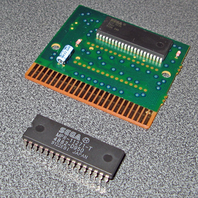
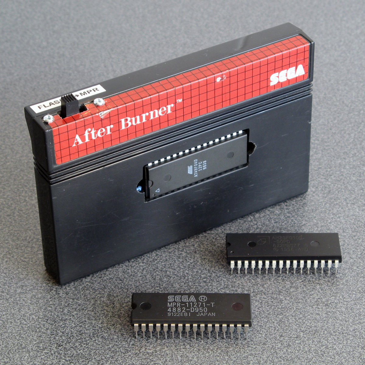
In the photo above you can see where I removed the mask ROM from the cartridge PCB and have left the mapper chip on the board. I didn't want to damage the old ROM chip (in case I wanted to play After Burner again) so I carefully unsoldered it rather than cutting it off the board. To do so I heated up each solder joint on the back of the board and used my spring-loaded solder sucker to remove the molten solder. After this I checked each pin by gently trying to move it in its hole; if it moved I knew it had been unsoldered and if it was stuck fast I knew I needed to try removing more solder. Once all pins were free the old ROM lifted cleanly out of the PCB.
One of convenient features of these cartridges is that the pinout of Sega's mask ROMs is virtually identical to the pinout of commonly-available flash memories like the 29F010 or 49F040. Only two pins need to be changed, as per the information on Charles MacDonald's website:
| Pin | Mask ROM | Flash memory |
|---|---|---|
| 1 | Not connected | A18 |
| 31 | A18 | /WE (Write Enable) |
As I wanted to ensure that the cartridge was compatible with both the original mask ROM and the replacement flash memory chip I thought it best to install a switch to let me select the type of memory that is installed. To break the connection between the solder pad on the PCB and the leg on the memory chip I used an IC socket with legs 1 and 31 bent out and not soldered through their corresponding holes. Wires are soldered to the bent out legs and go via the switch to the corresponding solder pads on the bottom of the PCB.
The position of A18 definitely needed to be swapped between pin 31 on the mask ROM and pin 1 on the flash memory if I wanted to be able to address all 512KB of a 4 megabit ROM. I had heard reports that the write enable pin on the flash memory can be left disconnected however the datasheets for the flash memory chips I checked did seem to indicate that it should be held high during read operations so I thought it best to hold it high when in "flash" mode. This means that the function of both pins needed to be changed by the switch, so I used a DPDT to make this happen. The two different states are illustrated below, showing the connections to the six pins on the bottom of the switch:
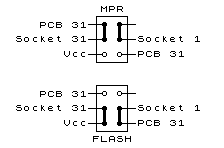
The heavy black lines show the position of the switch contacts when in the upper and lower positions. When in "MPR" mode you can see that pin 31 of the IC socket (A18) is connected to pin 31 of the PCB and pin 1 (NC) of the IC socket is not connected to anything. When in "FLASH" mode pin 31 of the IC socket (now /WE) is connected to Vcc and pin 1 of the IC socket (now A18) is connected to pin 31 of the PCB.
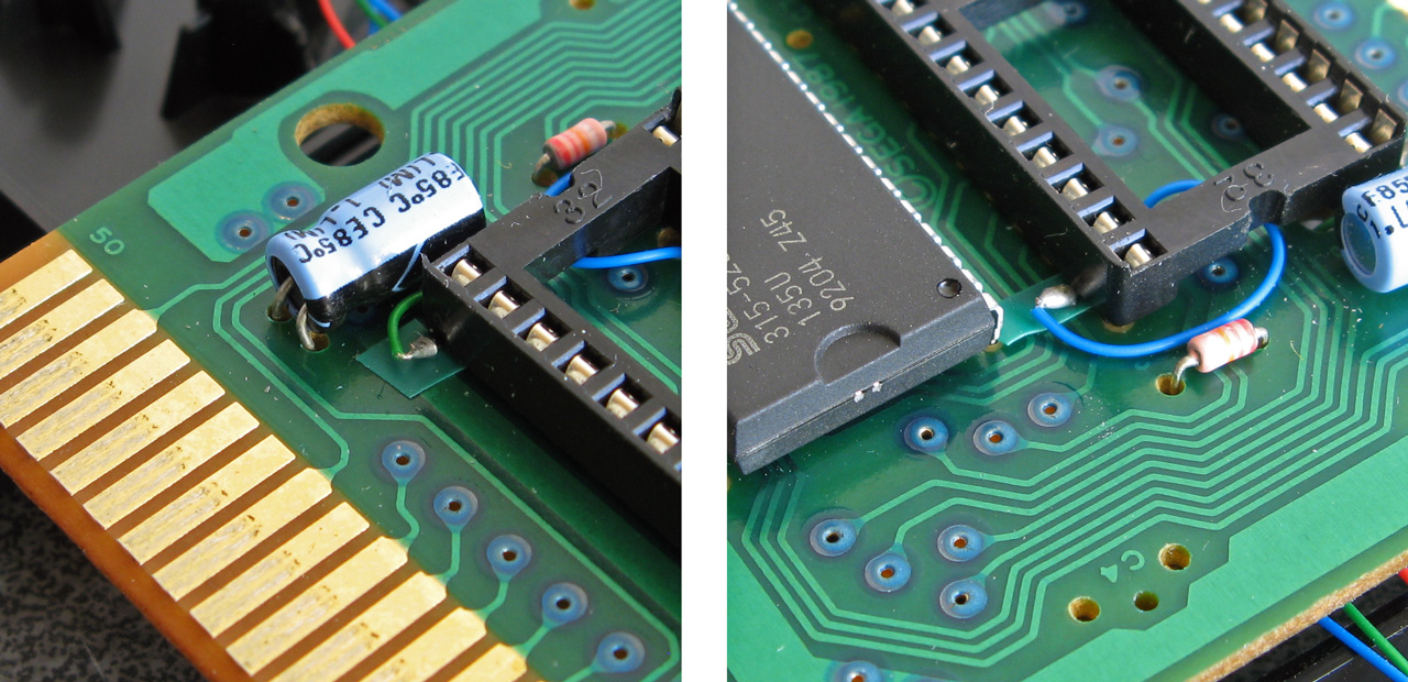
The photos above show how the pins of the IC socket were bent outwards with very fine wires soldered to them. These fine wires run through holes on the PCB under the IC socket to the underside. I did stick very small pieces of electrical insulating tape under the points where the solder joints for the wires attached to the bent pins made contact with the PCB for a bit of added security. With those legs bent out and the wires threaded through the PCB the socket could be soldered down.
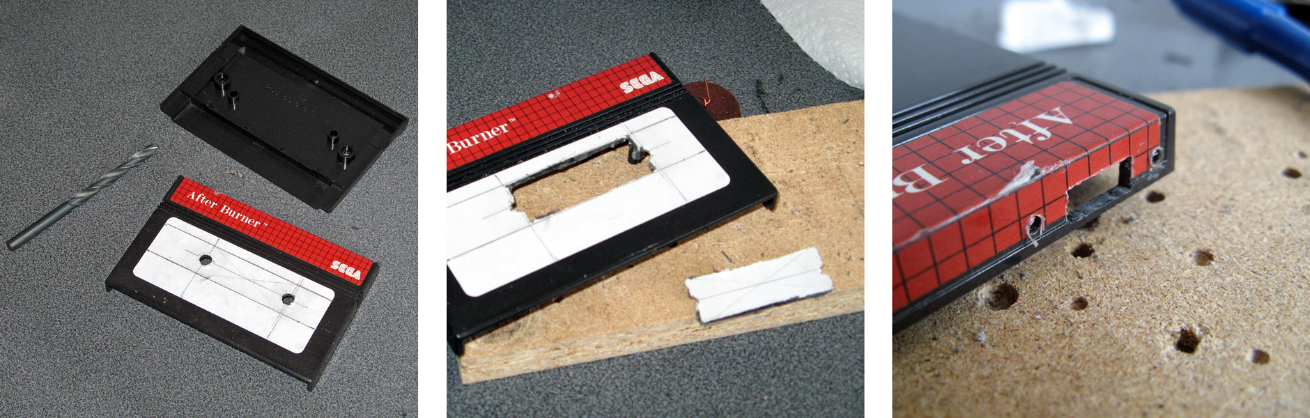
Unfortunately, one problem with using an IC socket is that the extra height means that the PCB no longer fits inside the cartridge shell. I needed to cut a rectangular hole in the cartridge enclosure for the chip to protrude through. I started by drilling two large round holes at the far ends of the chip - this allows me to use a chip puller (or small screwdriver) to pull (or lever) the chip out of the socket without needing to dismantle the cartridge each time. Due to the position of an internal support post very near to the memory chip a larger rectangular slot could not be cut – and I think this looks pretty neat anyway! A smaller rectangular hole was cut in the top of the cartridge shell for the switch to protrude through along with mounting holes for its two screws.
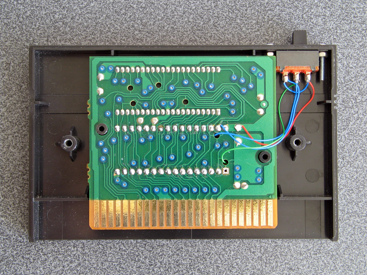
Here the switch has been mounted inside the case with the wires from the IC socket soldered to the appropriate pins on the switch and other wires connected to the appropriate pads on the back of the back of the PCB.
Inserting the original mask ROM for After Burner and setting the switch to MPR mode lets me play After Burner; writing a ROM image to a flash memory chip and inserting that with the switch set to FLASH mode let me run that program instead. Putting the switch on the wrong mode would take me to the console's built-in game of Hang On as the BIOS is no longer able to read the cartridge as a valid Master System game (at least when using a 512KB memory that requires A18 to be connected to the right pin). All in all I'm now happy that I have a way to run programs on my Master System from flash memory and do some homebrew experiments of my own on real hardware.
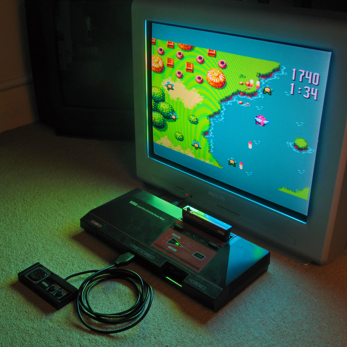
The above photo shows the excellent homebrew Flight of Pigarus by Kagesan running on my Master System courtesy of the modified cartridge. I've tested it so far with an AM29F010B (128KB/1 megabit) and an AT49F040 (512KB/4 megabit) and have been using the Willem programmer (along with Remapped IO.DLL to get it to work with my PC's PCI parallel port) to program the chips.