Ejecting discs from a damaged camcorder with a remote control
Tuesday, 29th December 2009
I hope that those of you who celebrate it had a good Christmas break and will have an excellent new year!
I recently attempted to repair a DVD camcorder that had been dropped; the eject button no longer worked, though the disc could be ejected by connecting to camera to a PC, right-clicking the DVD drive that subsequently appears in Explorer, then selecting Eject.
I started by removing all of the screws around the affected area, but the plastic casing remained strongly held together by some mysterious internal force. I removed more and more screws, but it soon became apparent that the only way to get into the camera would be to force it open – not being my camera, I didn't feel comfortable doing so, as the rest of the camera worked well and I didn't want to damage any fragile internal mechanisms. I couldn't find any dismantling guides online, so gave up on the idea of fixing the button.
Fortunately, I own the same model of camcorder – a Panasonic VDR-D250 – myself. With my interest in infrared remote controls I had previously found information about the Panasonic protocol it uses. The supplied remote control only has a few simple buttons on it (no eject button, sadly), but I reckoned that the camcorder may accept a number of other commands that the stock remote didn't include.
I started by modifying a universal remote control program for the TI-83+ that I had previous written to allow me to send specific commands to the camcorder, then ran through all of the possible command IDs, noting down those that appeared to have some effect. Eventually I had a pretty decent list, albeit one with quite a few gaps in it. Fortunately, I had found the Eject button code, along with codes to switch mode (which is done on the camera by rotating a mode dial), one that powers the camcorder off, another that appears to restart the camera and another one that resets all settings (not so useful, that one).
Having found the eject code, I set about building a dedicated remote control. I picked the ATtiny13 microcontroller as a base, as that's a more than capable microcontroller with its 9.6MHz internal clock, 1KB program memory, 64 bytes SRAM and 3V operation.
I was a bit surprised to see that AVR-GCC supports the ATtiny13, and whilst C may seem overkill for such a project I'll gladly take advantage of anything that makes my life easier. 
// Requisite header files.
#include <avr/io.h>
#include <util/delay.h>

// Frequency of the IR carrier signal (Hertz).
#define F_IR_CARRIER (37000)

// Timing of the data bits (microseconds).
#define T_DX_MARK   (440)
#define T_D0_SPACE  (440)
#define T_D1_SPACE (1310)

// Timing of the lead-in and lead-out bits (microseconds).
#define T_LEAD_IN_MARK    (3500)
#define T_LEAD_IN_SPACE   (1750)
#define T_LEAD_OUT_MARK    (440)
#define T_LEAD_OUT_SPACE (74000)

// Commands definitions.
#define OEM_DEVICE_1_CODE         (2)
#define OEM_DEVICE_2_CODE        (32)
#define CAMCORDER_DEVICE_ID     (112)
#define CAMCORDER_SUB_DEVICE_ID  (40)
#define CAMCORDER_COMMAND_EJECT   (1)

// Transmits a single unformatted byte.
void panasonic_send_byte(uint8_t value) {
    // Send eight data bits.
    for (uint8_t bit = 0; bit < 8; ++bit, value >>= 1) {
        // Send the mark/burst.
        DDRB |= _BV(1);
        _delay_us(T_DX_MARK);
        // Send the space.
        DDRB &= (uint8_t)~_BV(1);
        _delay_us(T_D0_SPACE);
        // Extend the space if it's a "1" data bit.
        if (value & (uint8_t)1) {
            _delay_us(T_D1_SPACE - T_D0_SPACE);
        }
    }
}

// Transmits a formatted command packet to the IR device.
void panasonic_send_command(uint8_t oem_device_code_1, uint8_t oem_device_code_2, uint8_t device_code, uint8_t sub_device_code, uint8_t command) {
    // Send the lead in.
    DDRB |= _BV(1);
    _delay_us(T_LEAD_IN_MARK);
    DDRB &= (uint8_t)~_BV(1);
    _delay_us(T_LEAD_IN_SPACE);

    // Send the five command bytes.
    panasonic_send_byte(oem_device_code_1);
    panasonic_send_byte(oem_device_code_2);
    panasonic_send_byte(device_code);
    panasonic_send_byte(sub_device_code);
    panasonic_send_byte(command);

    // Send the checksum.
    panasonic_send_byte(device_code ^ sub_device_code ^ command);

    // Send the lead out.
    DDRB |= _BV(1);
    _delay_us(T_LEAD_OUT_MARK);
    DDRB &= (uint8_t)~_BV(1);
    _delay_us(T_LEAD_OUT_SPACE);
}

// Main program entry point.
int main(void) {

    TCCR0A |= _BV(COM0B0) | _BV(WGM01);     // Toggle OC0B when on CTC reload. Use CTC mode.
    TCCR0B |= _BV(CS00);                    // Set clock source to CPU clock/1.
    OCR0A = (F_CPU / F_IR_CARRIER / 2) - 1; // Set the CTC reload value to generate an IR signal at the correct carrier frequency.

    // Send the "eject" command ad infinitum.
    for(;;) {
        panasonic_send_command(OEM_DEVICE_1_CODE, OEM_DEVICE_2_CODE, CAMCORDER_DEVICE_ID, CAMCORDER_SUB_DEVICE_ID, CAMCORDER_COMMAND_EJECT);
    }
}
The code is about as simple as the circuit. IR signals are transmitted as carefully timed bursts of a particular carrier frequency (37kHz in this case). For example, to send a "0" bit 440μS of this 37kHz signal are sent followed by 440μS of silence. To send a "1" bit, 440μS of carrier signal are sent as before, but a 1310μS period of silence follows it.
The AVR's timer is used to generate a ~37kHz carrier signal. The timer is an eight-bit counter that counts up at a user-defined rate (in my case I've chosen to increment the counter by one every CPU clock cycle). I've configured it to invert the output level of pin OC0B and reset every time it hits a particular value. By setting whether this pin is an output or an input the output of a burst of 37kHz IR signal or silence can be selected. Simple delay loops, generated with the helper function _delay_us, are used to time the transmission of data bits.
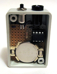
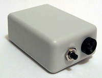
The final step was to assemble the circuit on stripboard and install it in a smallish project box. I've put the switch adjacent to the LED for two reasons; to conserve space and to protect it a little from accidentally being pressed by the protruding LED bezel.
Building a single-button remote control is a relatively straightforward affair, so whilst the above code has a very specific purpose it should be easy enough to modify it to control other devices.
Subscribe to an RSS feed that only contains items with the ATtiny13 tag.