Fixing the Menacer detection but breaking the accuracy of the aim tracking
Thursday, 26th March 2020
Since the last post about my experiments with using a Sega Light Phaser to play Mega Drive games I've had some good results and some disappointing ones that I'm still trying to work through.
The easy problem to solve was the handling of the buttons and making sure that the gun continued to be detected as a Menacer whenever a button was pressed. The previous circuit used active-high buttons (including an inverter to convert the active-low trigger from the Light Phaser into active-high signal) gated using the console's TH line via an AND gate. This meant that each button output a 0 when not pressed and 1 when pressed when TH was high, or a 0 in all cases whether TH was low or high.
When looking at the patent for the Menacer it became apparent that the button data lines were coming from a four-bit counter that is reset by the console's TR pin going high. When looking at logic analyser traces from T2: The Arcade Game we can see that TR is held high during device detection at the main menu screen but goes low during gameplay, being periodically pulsed high when the game alternates between handling light detection (short pulse) and reading button presses (long pulse). Rather than active-high buttons with AND gates, active-low buttons with NOR gates would seem to work better, so I ordered some NOR gate chips and tried the following circuit:
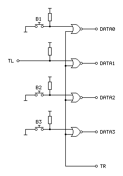
In the diagram above the TL on the left comes from the Light Phaser and the connections on the right go to the Mega Drive.
An OR gate will output a 1 if either of its inputs is a 1, to output a 0 both inputs have to be 0. A NOR gate inverts this output, so will output a 0 if either of the inputs is a 1 and will only output a 1 if both inputs are 0. When TR from the console is 1 it therefore forces the output to always be a 0, however if TR goes low to a 0 then the output is 0 if a button is released and 1 if a button is pressed – just what we needed.
Testing with T2: The Arcade Game I found that all of the buttons still worked during gameplay, and when pressing a button at the main menu the gun continued to be detected as a Menacer unlike the previous buggy implementation. All good so far!
I wanted to test with some other games, so ended up buying a copy of the six game cartridge that was originally bundled with the Menacer. I paid a little bit more and got a copy that came with the IR receiver, which is not much use without the gun however I thought it still might provider some interesting clues as to how to convert the signals from the Light Phaser to the Menacer protocol more correctly.
When the cartridge arrived I plopped it into my Mega Drive and was happy to see that the games mostly worked fine without any further tweaking. There was one fly in the ointment, however, an occasional message about the screen being too dark:
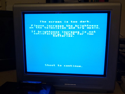
"The screen is too dark".
It would only do this occasionally when launching one of the six games and would then reset to the main intro and menu screen after shooting. Oddly, once a game was started I could quite happily move away from the TV to the other side of the room and the gun still worked reliably, so I'm not sure if this genuinely is an issue with the screen being too dark or if it's some problem with the way the gun is triggering the TH line on the console to indicate when it's seen light.
To try to get to the bottom of the issue I took apart the Menacer receiver and started sketching a circuit diagram based on the counter and NOR gate chips on the board. I then compared my scribbles to the circuit diagram in the patent, and found that the final implementation does appear to match the diagram in the patent pretty much exactly (I can't tell for certain as quite a lot of the circuitry is enclosed in a metal can, but all of the circuitry relating to the counter and NOR gate latch matches). This meant I was able to match up the console's pin connections to the diagram, which are unlabelled in the patent:
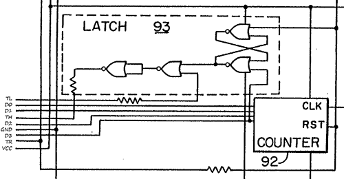
Pin connections for the Menacer receiver
It's not particularly clear due to how closely-packed the connections are in the diagram, however the important details are as follows:
- D0~D3 are connected to the counter directly, with D3 also going to set the latch at the top.
- TR resets the counter and the latch.
- TL appears to inhibit the output of the latch.
- TH only needs a 470Ω resistor between the output of the latch and the input to the console, not a common-emitter transistor driver.
I thought it would be neat if I could combine the function of the latch and the counter, so purchased a CD4017B decade counter chip as this has a handy clock inhibition input and wired it up as follows:
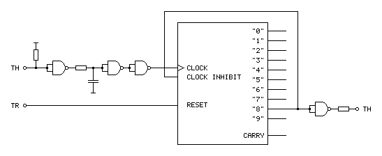
The clock input to this circuit comes from the TH output of the Light Phaser gun. This is an active-low signal so it needs to be inverted to properly clock the counter chip on the rising edge of the signal. It also needs to be delayed slightly for proper horizontal aiming (described in the previous post) so hence the additional RC circuit before the signal is fed to the counter chip.
With such a decade counter one of the 10 outputs labelled "0" to "9" is active at a time. After resetting the chip (by pulsing the reset pin high) "0" is high and "1" to "9" are low. When there is a rising edge at the clock input the chip counts up, so "0" goes low and "1" goes high, then "1" goes low and "2" goes high and so on and so forth. The "carry" output provides a rising edge clock signal when the counter overflows from "9" back to "0", allowing multiple chips to be chained together.
In the Menacer receiver the counter triggers the TH output latch on the fourth bit of a binary counter, i.e. when it reaches 8, so I've used the output of "8" as the output of the circuit. I've also fed this output back to the "clock inhibit" input of the counter chip. When this pin is low (which "8" will be when the counter is reset) it allows the counter to count up normally whenever the clock pin is pulsed. When the pin goes high (which "8" will be when we've seen eight pulses of light from the gun) it will inhibit the counter from counting any further, effectively locking it at "8". The only way out of this condition is to reset the chip, which the console does by pulsing the TR input line.
The only additional complication is that the console still expects an active low signal from the gun, so the final step is to invert the output from the counter.
Unfortunately, this does not work at all well. Games no longer seem to produce the "The screen is too dark" message, however aiming is extremely laggy and inaccurate. Checking the output of the counter with a logic probe seems to indicate erratic triggering. Using a different output from the counter (e.g. "4" or even "1") so that the counter "latches" sooner seems to improve things slightly but overall performance is still far worse in this arrangement. I'm not entirely sure why!
My next attempt was to simplify matters by using the exact latch circuit composed of NOR gates described in the patent, which worked just about as badly – the circuit still triggered eratically and accuracy was very poor. I have had issues with circuits not triggering properly before when using particular logic chips (it's why the circuit for my LCD Shutter Glasses adaptor has SN74LS14N Schmitt-trigger invertors on the logic inputs) so I thought I'd try replacing the CD4001B CMOS NOR gate chip I was using with the SN74ALS00AN TTL NAND gate chip I was using in previous experiments. The logic for a latch built from NAND gates is inverted to the logic of one built from NOR gates so it wasn't a straight swap but I don't have any other NOR gates in my parts bin. Somewhat surprisingly, with this new chip performance was greatly improved, though still not quite right.
For my next set of experiments I'm going to try replacing the CMOS NOR gate with the TTL NOR equivalent, though as that will involve waiting for parts to turn up in the post I thought I'd write a quick update on where I am so far. Fingers crossed this issue can be resolved easily and with a simple circuit!