1-Wire interfacing with the Cambridge Z88
Sunday, 17th December 2023
I've been having a tricky time buying LM35DZ analogue temperature sensors for a project recently. One pair of probes and a bag of loose components labelled LM35DZ turned out to be regular NPN transistors with a fake label on them, and another pair of probes ended up being DS18B20 digital temperature sensors.
Whilst the DS18B20 temperature sensors were useless for the project I had in mind they were still functioning components. These use the 1-Wire serial bus, a bus named for the way that its single data line can also be used to parasitically power the devices on the bus. Electrically the bus is open drain with a pull-up resistor that idles in the high state which any device can drive low. The master initiates all communication and you can have multiple peripheral devices connected to the bus in an arrangement called a MicroLAN.
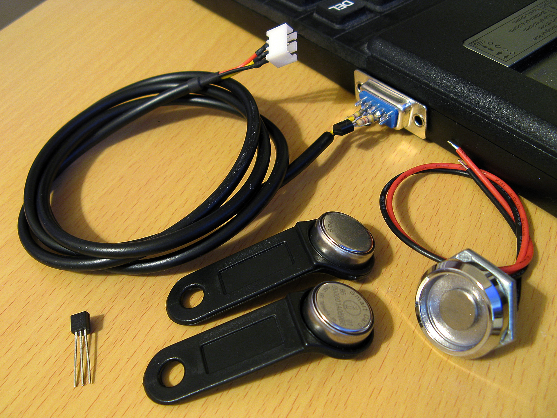
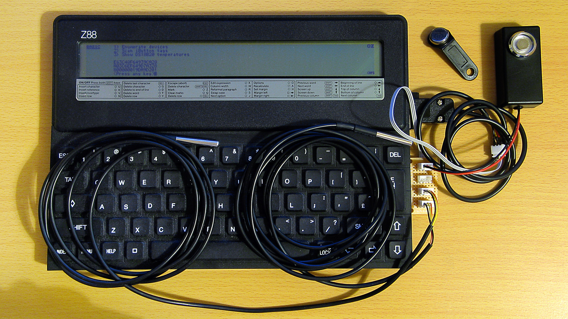
A selection of 1-Wire devices and a 1-Wire interface adaptor plugged into a Z88 computer
I'd had some limited experience working with the 1-Wire bus as part of my version of the Superprobe but now that I had a collection of temperature sensors I thought it might be worth revisiting, this time on the Cambridge Z88.
1-Wire adaptor for the Z88 serial port
To connect 1-Wire devices to the Z88 some sort of adaptor is required and one that plugged into the computer's serial port seemed like a sensible enough option. The Z88's serial port hardware normally handles all the communications for you however it is possible to directly control the logic levels of the serial port's output pins and read back the status of the input pins via some hardware registers.
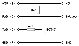
The TXD line can be +5V for a logic 0 and -6V for a logic 1, adhering to the RS-232 standard. When idle TXD is in its logic 1 state, outputting -6V. Bit ITX (3) in the TXC (&E4) register can be used to invert the behaviour of the TXD pin, so by setting this bit we can change the state of the pin from -6V to +5V.
As we need to have an open-drain bus we can use an NPN transistor with the base connected to the TXD line via a current-limiting resistor, the emitter connected to ground and the collector driving the 1-Wire bus. By default the TXD pin will output -6V, the transistor will be switched off and the bus will be pulled high. When the TXD pin state is inverted it will output +5V, the transistor will switch on and drive the line low.
The state of the RXD line can be read directly via bit RXD (4) in the RXE (&E1) register. The lines appear to be weakly held to 0V and read back a 0 bit in this state, flipping to a 1 bit when the voltage rises above around 2V. In this case we can connect the 1-Wire bus directly to the RXD input and be able to read back the current state.
The circuit for the adaptor, including the 4.7K pull-up resistor, appears as follows:
This can be tested in a BASIC program. To determine the input state we can read from the RXE port register (&E1) and check the state of the RXD bit (4):
10 RXE=&E1:M_RXERXD=&10
20 REPEAT
30   PRINT ~(GET(RXE) AND M_RXERXD)
40 UNTIL FALSE
The mask value M_RXERXD is specified as 24=&10 to correspond to the bit four. When run this program displays &10 in hex (showing bit 4 is set and the bus level is therefore high) until the 1-Wire bus line is connected to ground, when the value changes to 0 (showing bit 4 is reset and the bus level is therefore low).
To change the output state we need to write to bit ITX (3) of the TXC register (&E4). However, when writing to the hardware port we only want to change that bit and leave the others alone. The TXC register is a write-only port, so we can't retrieve its previous state by reading from the port. Fortunately the OS maintains a copy of the last value written as a "soft copy" in RAM at address &04E4 and this can be read with the ? indirection operator:
10 TXC=&E4:M_TXCITX=&08
20 SC=&400
30 TXC_OLD=SC?TXC
40 PUT TXC,TXC_OLD OR M_TXCITX
50 IF INKEY(100)
60 PUT TXC,TXC_OLD
The above program reads the old state of the TXC port from the soft copy, ORs it with the mask of the ITX bit (23=&08) and then outputs that to the TXC port. This has the effect of inverting the TXD line, driving the 1-Wire bus low. The program then waits one second with a dummy keyboard read before restoring the old value of the TXC port to release the 1-Wire bus.
Normally if changing the state of the serial port it would be good manners to update the soft copy of the serial port state however as the program is just going to be sending short low pulses before returning the port to its previous state this step is omitted.
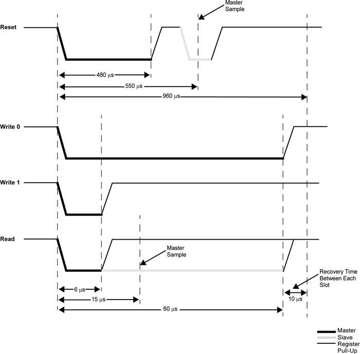
After testing that the circuit worked on a breadboard a more permanent version was assembled in a DE-9 shell as above. As the clips that hold in the DE-9 connector had to cut off to allow it to fit in the Z88's recessed port the circuit ended up being secured with copious amounts of hot glue, which is far from ideal, but nobody will see when it's all screwed back together.
Bit-level protocol
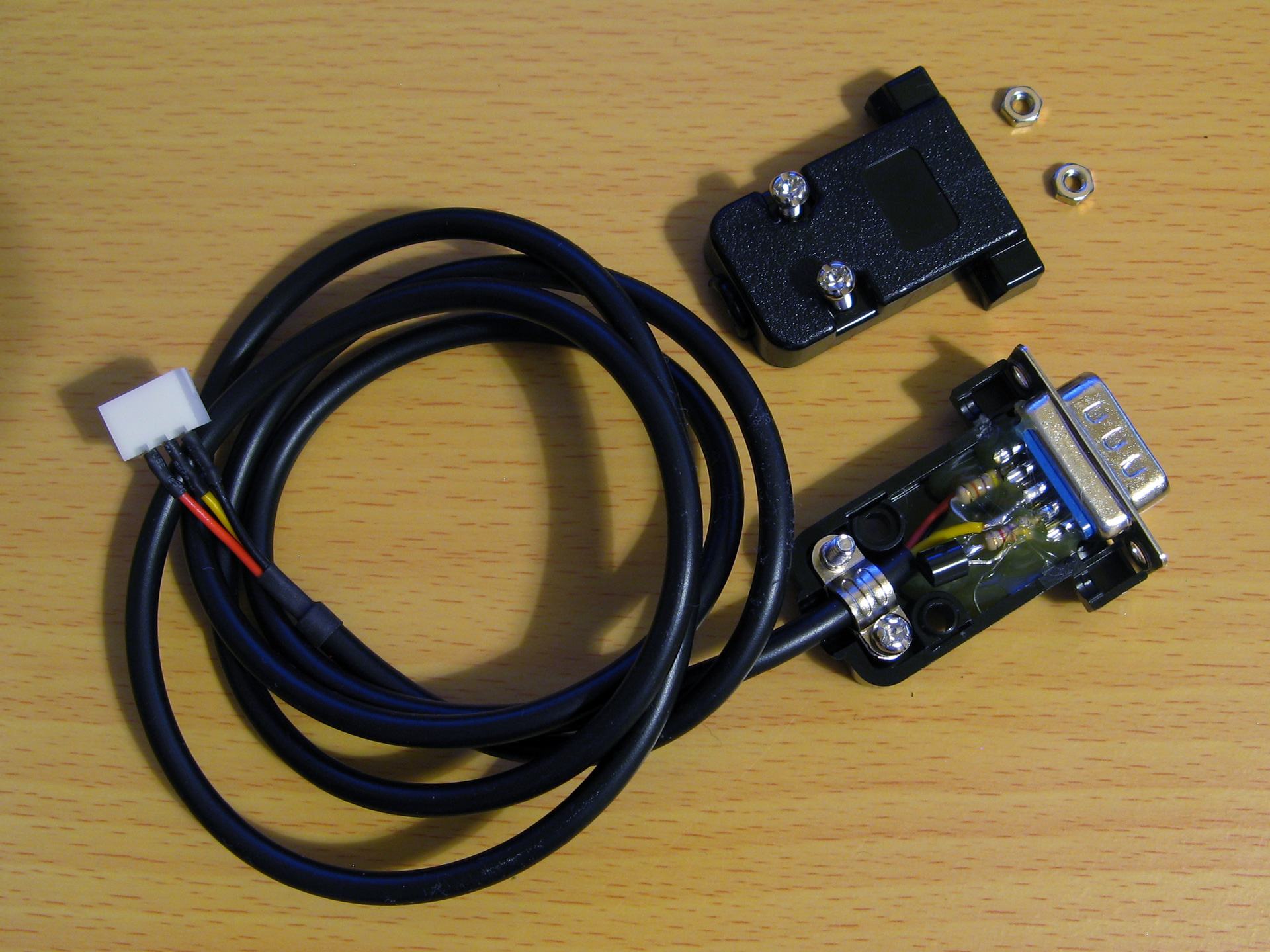
Now that we can electrically control the bus we need to know how to transfer data on it. This is done by timed pulses, where the bus master will hold the bus line low for a certain amount of time, release it, then check to see if any devices on the bus are holding it low in return. This is summarised in the following timing diagram from Microchip's AN1199, 1-Wire Communication with PIC Microcontroller:
The first thing that needs to be done is to reset all devices on the bus. This is done by holding the bus low for 480μs then releasing it for at least 480μs. If any peripheral devices are present on the bus they will drive the line low after the low pulse from the master, so the full reset procedure is as follows:
- Master drives bus low
- Delay 480μs
- Master releases bus high
- Delay 70μs
- Sample bus state: if high, no peripheral devices present, if low at least one device present.
- Delay 410μs
Once reset, data can be transmitted from the master to peripheral devices bit-by-bit in a similar fashion to the reset pulse, albeit with different timing.
To send a 0 bit:
- Master drives bus low
- Delay 60μs
- Master releases bus high
- Delay 10μs
To send a 1 bit:
- Master drives bus low
- Delay 6μs
- Master releases bus high
- Delay 64μs
Bytes are transferred as eight individual bits, least-significant bit first. The protocol is also tolerant of large delays between individual bits.
Once data has been sent to a peripheral, it may respond with data of its own. The master is still in control of clocking the data out of the peripheral, and the process is as follows:
- Master drives bus low
- Delay 6μs
- Master releases bus high
- Delay 9μs
- Sample bus state to read data bit from peripheral
- Delay 55μs
The overall timing for reading a bit is the same as the timing for sending a 1 bit (an initial 6μs low pulse from the master and a total bit time of 70μs) so in practice only one routine needs to be implemented and the value returned from the bus during read operations can be ignored during write operations.
Software choice for the Z88
I thought it would be nice to be able to interact with 1-Wire devices from a BASIC program. BBC BASIC on the Z88 does provide direct access to the hardware and would make controlling the 1-Wire bus line possible, as demonstrated earlier, however I don't think it would provide the timing accuracy required to produce the appropriate pulses from the master. Fortunately it does include a Z80 assembler and so a mixture of a BASIC program that provides the high-level routines and assembly snippets for the low-level 1-Wire protocol implementation seemed like an appropriate mix of languages.
When you CALL an assembly routine from BASIC the Z80's registers are initialised to the values of the corresponding static variables, for example A is set to A%, H to H%, L to L% etc. You can't return a value directly – for that you'd need USR – however it's a bit easier to just store the return value in memory and retrieve that from BASIC after the CALL returns.
A rough starting point for the 1-Wire program is as follows:
 10 REM 1-WIRE DEMO
 20 PROC_1W_INIT
 30 PRINT FN_1W_RESET
 40 END
 50 :
 60 REM 1-WIRE ROUTINES
 70 END
 80 DEFPROC_1W_INIT
 90 ow_code_size=256:DIM ow_code ow_code_size-1
100 RXE=&E1:M_RXERXD=&10
110 TXC=&E4:M_TXCITX=&08
120 SC=&400
130 FOR opt=0 TO 2 STEP 2
140   P%=ow_code
150   [OPT opt
160   .ow_buf DEFB 0 \ temporary transfer buffer
170   :
180   .ow_reset
190   IN A,(RXE):AND M_RXERXD:CP M_RXERXD:SBC A,A:LD (ow_buf),A:RET NZ \ check bus is idle
200   DI:LD A,(SC+TXC):OR M_TXCITX:OUT (TXC),A \ hold bus low
210   LD B,120:DJNZ P% \ delay
220   AND NOT M_TXCITX:OUT (TXC),A \ release bus
230   LD B,18:DJNZ P% \ delay
240   IN A,(RXE):AND M_RXERXD:CP M_RXERXD:CCF:SBC A,A:LD (ow_buf),A \ sample presence
250   LD B,100:DJNZ P% \ delay
260   EI:RET
270   :
280   ]
290 NEXT
300 ENDPROC
310 :
320 REM Resets bus, retuns TRUE if any devices are present
330 DEFFN_1W_RESET:CALL ow_reset:=?ow_buf=0
The first few lines are going to be where our BASIC program is. This calls the procedure PROC_1W_INIT which will set things up by assembling any required Z80 code. It then calls FN_1W_RESET which is a function that resets the 1-Wire bus and checks to see if any devices assert their presence.
PROC_1W_INIT starts by allocating some memory for the assembled code to live, defines some constants for the IO ports and then runs through the two passes of the assembly process in a loop. Within the assembly block is a variable (ow_buf) which will be used to store data due to be returned by the assembly routines. The ow_reset assembly routine then follows – this first checks to see if the bus is idle (floating high) and if so it disables interrupts, holds the bus low for 480μs, releases the bus and waits 70μs, samples the state of the bus to check for device presence (storing the result in ow_buf), then delays another 410μs.
The delay loops are simple DJNZ loops with B corresponding to the length of the delay and the timings were roughly calculated first based on the number of cycles each loop would take and the Z88's 3.2768MHz CPU clock speed. They were then adjusted slightly using a logic analyser to ensure the timing was as close as could be managed to the 1-Wire protocol's specifications.
The ow_reset routine has been written so that following a successful presence check ow_buf should contain 0, and if there is a problem it will contain a non-zero value. This is used by the FN_1W_RESET wrapper function which just calls ow_reset and returns TRUE if ow_buf is zero afterwards.
If you run the program you should see that the program will display 0 (FALSE) on the screen until a 1-Wire device is connected to the adaptor, at which point it will display -1 (TRUE) instead to indicate the device's presence. This isn't a very useful program, but shows how BASIC and assembly will be mixed to build the rest of the 1-Wire routines.
Sending and receiving bits and bytes
Now that we know a device is present on the bus after a reset we need to be able to send and receive bits and bytes. Sending a 0 bit is a bit simpler than resetting, as we don't need to check for any response – just hold the line low for 60μs then release it back high for 10μs. This can be implemented as follows:
.ow_put_0
DI
LD A,(SC+TXC):OR M_TXCITX:OUT (TXC),A \ hold bus low
LD B,15:DJNZ P% \ delay
AND NOT M_TXCITX:OUT (TXC),A \ release bus
NOP \ delay
EI:RET
Sending a 1 bit has the same overall timing as reading a bit, so instead of writing separate routines to send a 1 bit and read a bit just one routine is required that handles both situations:
.ow_put_1
DI
LD A,(SC+TXC):OR M_TXCITX:OUT (TXC),A \ hold bus low
NOP \ delay
AND NOT M_TXCITX:OUT (TXC),A \ release bus
PUSH HL:POP HL \ delay
IN A,(RXE):AND M_RXERXD:SUB M_RXERXD:CCF \ sample bit
LD A,(ow_buf):RRA:LD (ow_buf),A \ store bit
LD B,7:DJNZ P% \ delay
EI:RET
This holds the bus low for 6μs, releases it and waits 9μs, samples a bit from the bus and rotates it into the ow_buf transfer buffer, then waits 55μs.
These routines could be wrapped up for use in BASIC but it's not too useful to be able to send or receive single bits, normally we'd need to transfer whole 8-bit bytes. The ow_put_1 routine already handles updating the ow_buf with each received bit, so a byte receiving routine can be put together by just calling ow_put_1 eight times in a loop:
.ow_get_byte
LD B,8 \ 8 bits to receive
.ow_get_loop
PUSH BC:CALL ow_put_1:POP BC \ receive single bit
DJNZ ow_get_loop \ loop
LD A,(ow_buf):RET \ store
A send routine can be put together with a similar loop that shifts out the bit to send and then calls either the ow_put_0 or ow_put_1 routine depending on whether it's a 0 or 1 bit that's required. Bits will usually be shifted out into the carry register, so a new ow_put_carry routine that sends the bit stored in the carry flag makes this a bit easier, e.g.
.ow_put_carry
JR C,ow_put_1
JR ow_put_0
...which will be called by the ow_put_byte routine, as follows:
.ow_put_byte
LD C,A:LD B,8 \ value to send in C, send 8 bits
.ow_put_loop
SRL C:PUSH BC:CALL ow_put_carry:POP BC \ shift and send single bit
DJNZ ow_put_loop \ loop
RET
It is also quite useful to be able to send or receive blocks of data at once – for example, sending or receiving the 64-bit device IDs requires sending or receiving 8 bytes of data at a time. To complement ow_get_byte and ow_put_byte we can write ow_get_bytes and ow_put_bytes routines to send or receive the block of data addressed by HL, length BC:
.ow_get_bytes
LD A,B:OR C:RET Z:DEC BC \ have we finished?
PUSH BC:CALL ow_get_byte:POP BC \ get a byte
LD (HL),A:INC HL:JR ow_get_bytes \ store and loop
:
.ow_put_bytes
LD A,B:OR C:RET Z:DEC BC \ have we finished?
LD A,(HL):INC HL \ fetch
PUSH BC:CALL ow_put_byte:POP BC:JR ow_put_bytes \ send and loop
All of these can now be wrapped up as procedures or functions so they can be more easily used from a BASIC program:
REM Transmits a single byte
DEFPROC_1W_PUT(A%)CALL ow_put_byte:ENDPROC
REM Transmits a block of bytes
DEFPROC_1W_PUTS(L%,C%)LOCAL H%,B%:H%=L%DIV256:B%=C%DIV256:CALL ow_put_bytes:ENDPROC
REM Receives a single byte
DEFFN_1W_GET:CALL ow_get_byte:=?ow_buf
REM Receives a block of bytes
DEFPROC_1W_GETS(L%,C%)LOCAL H%,B%:H%=L%DIV256:B%=C%DIV256:CALL ow_get_bytes:ENDPROC
BASIC's integer variables are 32-bit integers so when passing the 16-bit address or length parameters the target register is the least-significant one (L for HL, C for BC) and the most-significant register (H or B) is populated by dividing the value by 256.
This can all be put together in the following demonstration program. It initialises the routines, resets the bus and checks for presence, then sends the "read ROM" command &33 which will make any connected devices respond with their ROM ID. It then reads back the eight bytes corresponding to the device ID then prints them back in hexadecimal.
 10 DIM ID 7:REM Storage for device ID
 20 PROC_1W_INIT
 30 IF FN_1W_RESET=FALSE PRINT "No devices found.":END
 40 PROC_1W_PUT(&33):REM "Read ROM" command
 50 PROC_1W_GETS(ID,8):REM Read eight bytes of device ID
 60 FOR I=7 TO 0 STEP -1:PRINT ~ID?I;:NEXT:PRINT:REM Print device ID bytes
 70 END
 80 :
 90 REM 1-WIRE ROUTINES
100 END
110 DEFPROC_1W_INIT
120 ow_code_size=256:DIM ow_code ow_code_size-1
130 RXE=&E1:M_RXERXD=&10
140 TXC=&E4:M_TXCITX=&08
150 SC=&400
160 FOR opt=0 TO 2 STEP 2
170   P%=ow_code
180   [OPT opt
190   .ow_buf DEFB 0 \ temporary transfer buffer
200   :
210   .ow_reset
220   IN A,(RXE):AND M_RXERXD:CP M_RXERXD:SBC A,A:LD (ow_buf),A:RET NZ \ check bus is idle
230   DI:LD A,(SC+TXC):OR M_TXCITX:OUT (TXC),A \ hold bus low
240   LD B,120:DJNZ P% \ delay
250   AND NOT M_TXCITX:OUT (TXC),A \ release bus
260   LD B,18:DJNZ P% \ delay
270   IN A,(RXE):AND M_RXERXD:CP M_RXERXD:CCF:SBC A,A:LD (ow_buf),A \ sample presence
280   LD B,100:DJNZ P% \ delay
290   EI:RET
300   :
310   .ow_put_carry
320   JR C,ow_put_1 \ fall-through
330   :
340   .ow_put_0
350   DI
360   LD A,(SC+TXC):OR M_TXCITX:OUT (TXC),A \ hold bus low
370   LD B,15:DJNZ P% \ delay
380   AND NOT M_TXCITX:OUT (TXC),A \ release bus
390   NOP \ delay
400   EI:RET
410   :
420   .ow_put_1
430   DI
440   LD A,(SC+TXC):OR M_TXCITX:OUT (TXC),A \ hold bus low
450   NOP \ delay
460   AND NOT M_TXCITX:OUT (TXC),A \ release bus
470   PUSH HL:POP HL \ delay
480   IN A,(RXE):AND M_RXERXD:SUB M_RXERXD:CCF \ sample bit
490   LD A,(ow_buf):RRA:LD (ow_buf),A \ store bit
500   LD B,7:DJNZ P% \ delay
510   EI:RET
520   :
530   .ow_put_byte
540   LD C,A:LD B,8 \ value to send in C, send 8 bits
550   .ow_put_loop
560   SRL C:PUSH BC:CALL ow_put_carry:POP BC \ shift and send single bit
570   DJNZ ow_put_loop \ loop
580   RET
590   :
600   .ow_put_bytes
610   LD A,B:OR C:RET Z:DEC BC \ have we finished?
620   LD A,(HL):INC HL \ fetch
630   PUSH BC:CALL ow_put_byte:POP BC:JR ow_put_bytes \ send and loop
640   :
650   .ow_get_byte
660   LD B,8 \ 8 bits to receive
670   .ow_get_loop
680   PUSH BC:CALL ow_put_1:POP BC \ receive single bit
690   DJNZ ow_get_loop \ loop
700   LD A,(ow_buf):RET \ store
710   :
720   .ow_get_bytes
730   LD A,B:OR C:RET Z:DEC BC \ have we finished?
740   PUSH BC:CALL ow_get_byte:POP BC \ get a byte
750   LD (HL),A:INC HL:JR ow_get_bytes \ store and loop
760   :
770   ]
780 NEXT
790 IF P%-ow_code>ow_code_size PRINT"Code size: "P%-ow_code:END
800 ENDPROC
810 :
820 REM Resets bus, retuns TRUE if any devices are present
830 DEFFN_1W_RESET:CALL ow_reset:=?ow_buf=0
840 REM Transmits a single byte
850 DEFPROC_1W_PUT(A%)CALL ow_put_byte:ENDPROC
860 REM Transmits a block of bytes
870 DEFPROC_1W_PUTS(L%,C%)LOCAL H%,B%:H%=L%DIV256:B%=C%DIV256:CALL ow_put_bytes:ENDPROC
880 REM Receives a single byte
890 DEFFN_1W_GET:CALL ow_get_byte:=?ow_buf
900 REM Receives a block of bytes
910 DEFPROC_1W_GETS(L%,C%)LOCAL H%,B%:H%=L%DIV256:B%=C%DIV256:CALL ow_get_bytes:ENDPROC
When connected to an iButton fob the program prints
55 0 0 1 A0 1A 57 1
...which matches the ID printed on it.
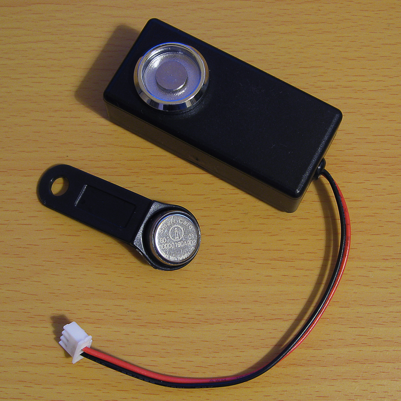
An example of a TM1990A iButton fob (middle) along with the probe used to read it (top)
When connected to a DS18B20 temperature sensor the program prints
B9 0 0 1 D1 97 5D 28
The least significant byte of the 64-bit ID is the family code – &01 for the iButton fob indicates it's a "silicon serial number" type device and &28 for the DS18B20 indicates it's a "programmable resolution digital thermometer".
The 1-Wire bus supports multiple peripheral devices connected to a single master. If we try that we still get something that looks like an ID back:
11 0 0 1 80 12 55 0
This happens because it's an open-drain bus and any device holding the line low will take priority over any device releasing the line high. In effect the data read back is ANDed together, so the most-significant byte received is &55 AND &B9 which gives us the &11 we see. Fortunately that most-significant byte does give us a good opportunity to detect such invalid data!
Error detection with a CRC
Some data payloads include a CRC value. The most-significant byte of a 64-bit device ID is such a CRC, with the least-significant byte being the family code. The exact details for the CRC calculation can be found in the article Understanding and Using Cyclic Redundancy Checks with Maxim 1-Wire and iButton Products however for our purposes a Z80 implementation can be written as follows:
.ow_crc
LD B,8:LD DE,(ow_buf):LD D,A \ E = accumulated CRC, D = value to add
.ow_crc_loop
LD A,E:XOR D:SRL D:SRL A:JR C,ow_crc_odd \ XOR and shift bits
SRL E:DJNZ ow_crc_loop:LD A,E:LD (ow_buf),A:RET \ even CRC value
.ow_crc_odd:SRL E:LD A,&8C:XOR E:LD E,A:DJNZ ow_crc_loop:LD (ow_buf),A:RET \ odd CRC value
:
.ow_crc_block
XOR A:LD (ow_buf),A \ reset CRC
.ow_crc_block_loop
LD A,B:OR C:LD A,(ow_buf):RET Z:DEC BC \ have we finished?
LD A,(HL):INC HL:PUSH BC:CALL ow_crc:POP BC:JR ow_crc_block_loop \ update CRC
ow_crc updates the current calculated CRC value (stored in ow_buf) with the next data byte from the accumulator. ow_crc_block calculates the CRC for a block of data pointed to by HL, length BC, using the ow_crc routine. A couple of BASIC functions can then be written, one to calculate the CRC of a block of data and another to check that the last byte of the block corresponds to the CRC of the preceding data:
REM Calculates the CRC of a block of data
DEFFN_1W_CRC(L%,C%)LOCAL H%,B%:H%=L% DIV256:B%=C%DIV256:CALL ow_crc_block:=?ow_buf
REM Checks if a CRC at the end of a block of data matches
DEFFN_1W_CRC_CHECK(L%,C%)=FN_1W_CRC(L%,C%)=(L%?C%)
These two can now be used to check that a device ID is valid. The CRC is also appended to other data reports, such as reading the scratchpad memory of a temperature sensor, so it's a useful routine to have. A new program which checks the CRC is as follows:
 10 DIM ID 7
 20 PROC_1W_INIT
 30 REPEAT
 40   REPEAT UNTIL FN_1W_RESET:REM Wait for device to be present
 50   PROC_1W_PUT(&33):REM Read ROM
 60   PROC_1W_GETS(ID,8):REM Fetch ID
 70   IF FN_1W_CRC_CHECK(ID,7) VDU 7:PRINT "Detected ";FN_1W_ID$(ID);" at ";TIME$:REM Print if valid
 80   REPEAT UNTIL FN_1W_RESET=FALSE:REM Wait for device to be disconnected
 90 UNTIL FALSE
100 END
110 :
120 REM 1-WIRE ROUTINES
130 END
140 DEFPROC_1W_INIT
150 ow_code_size=256:DIM ow_code ow_code_size-1
160 RXE=&E1:M_RXERXD=&10
170 TXC=&E4:M_TXCITX=&08
180 SC=&400
190 FOR opt=0 TO 2 STEP 2
200   P%=ow_code
210   [OPT opt
220   .ow_buf DEFB 0 \ temporary transfer buffer
230   .ow_conf DEFB 0 \ stores last bit conflict index
240   :
250   .ow_reset
260   IN A,(RXE):AND M_RXERXD:CP M_RXERXD:SBC A,A:LD (ow_buf),A:RET NZ \ check bus is idle
270   DI:LD A,(SC+TXC):OR M_TXCITX:OUT (TXC),A \ hold bus low
280   LD B,120:DJNZ P% \ delay
290   AND NOT M_TXCITX:OUT (TXC),A \ release bus
300   LD B,18:DJNZ P% \ delay
310   IN A,(RXE):AND M_RXERXD:CP M_RXERXD:CCF:SBC A,A:LD (ow_buf),A \ sample presence
320   LD B,100:DJNZ P% \ delay
330   EI:RET
340   :
350   .ow_put_carry
360   JR C,ow_put_1 \ fall-through
370   :
380   .ow_put_0
390   DI
400   LD A,(SC+TXC):OR M_TXCITX:OUT (TXC),A \ hold bus low
410   LD B,15:DJNZ P% \ delay
420   AND NOT M_TXCITX:OUT (TXC),A \ release bus
430   NOP \ delay
440   EI:RET
450   :
460   .ow_put_1
470   DI
480   LD A,(SC+TXC):OR M_TXCITX:OUT (TXC),A \ hold bus low
490   NOP \ delay
500   AND NOT M_TXCITX:OUT (TXC),A \ release bus
510   PUSH HL:POP HL \ delay
520   IN A,(RXE):AND M_RXERXD:SUB M_RXERXD:CCF \ sample bit
530   LD A,(ow_buf):RRA:LD (ow_buf),A \ store bit
540   LD B,7:DJNZ P% \ delay
550   EI:RET
560   :
570   .ow_put_byte
580   LD C,A:LD B,8 \ value to send in C, send 8 bits
590   .ow_put_loop
600   SRL C:PUSH BC:CALL ow_put_carry:POP BC \ shift and send single bit
610   DJNZ ow_put_loop \ loop
620   RET
630   :
640   .ow_put_bytes
650   LD A,B:OR C:RET Z:DEC BC \ have we finished?
660   LD A,(HL):INC HL \ fetch
670   PUSH BC:CALL ow_put_byte:POP BC:JR ow_put_bytes \ send and loop
680   :
690   .ow_get_byte
700   LD B,8 \ 8 bits to receive
710   .ow_get_loop
720   PUSH BC:CALL ow_put_1:POP BC \ receive single bit
730   DJNZ ow_get_loop \ loop
740   LD A,(ow_buf):RET \ store
750   :
760   .ow_get_bytes
770   LD A,B:OR C:RET Z:DEC BC \ have we finished?
780   PUSH BC:CALL ow_get_byte:POP BC \ get a byte
790   LD (HL),A:INC HL:JR ow_get_bytes \ store and loop
800   :
810   .ow_crc
820   LD B,8:LD DE,(ow_buf):LD D,A \ E = accumulated CRC, D = value to add
830   .ow_crc_loop
840   LD A,E:XOR D:SRL D:SRL A:JR C,ow_crc_odd \ XOR and shift bits
850   SRL E:DJNZ ow_crc_loop:LD A,E:LD (ow_buf),A:RET \ even CRC value
860   .ow_crc_odd:SRL E:LD A,&8C:XOR E:LD E,A:DJNZ ow_crc_loop:LD (ow_buf),A:RET \ odd CRC value
870   :
880   .ow_crc_block
890   XOR A:LD (ow_buf),A \ reset CRC
900   .ow_crc_block_loop
910   LD A,B:OR C:LD A,(ow_buf):RET Z:DEC BC \ have we finished?
920   LD A,(HL):INC HL:PUSH BC:CALL ow_crc:POP BC:JR ow_crc_block_loop \ update CRC
930   ]
940 NEXT
950 IF P%-ow_code>ow_code_size PRINT"Code size: "P%-ow_code:END
960 ENDPROC
970 :
980 REM Resets bus, retuns TRUE if any devices are present
990 DEFFN_1W_RESET:CALL ow_reset:=?ow_buf=0
1000 REM Transmits a single byte
1010 DEFPROC_1W_PUT(A%)CALL ow_put_byte:ENDPROC
1020 REM Transmits a block of bytes
1030 DEFPROC_1W_PUTS(L%,C%)LOCAL H%,B%:H%=L%DIV256:B%=C%DIV256:CALL ow_put_bytes:ENDPROC
1040 REM Receives a single byte
1050 DEFFN_1W_GET:CALL ow_get_byte:=?ow_buf
1060 REM Receives a block of bytes
1070 DEFPROC_1W_GETS(L%,C%)LOCAL H%,B%:H%=L%DIV256:B%=C%DIV256:CALL ow_get_bytes:ENDPROC
1080 :
1090 REM Converts ID bytes into string
1100 DEFFN_1W_ID$(ID)LOCAL I%:S$="":FOR I%=7 TO 0 STEP -1:IF ID?I%>15:S$=S$+STR$~(ID?I%):NEXT:=S$:ELSE:S$=S$+"0"+STR$~(ID?I%):NEXT:=S$
1110 REM Converts string into ID bytes
1120 DEFPROC_1W_ID$(ID,ID$)LOCAL I%:FOR I%=0 TO 7:ID?I%=EVAL("&"+MID$(ID$,15-I%*2,2)):NEXT:ENDPROC
1130 :
1140 REM Calculates the CRC of a block of data
1150 DEFFN_1W_CRC(L%,C%)LOCAL H%,B%:H%=L% DIV256:B%=C%DIV256:CALL ow_crc_block:=?ow_buf
1160 REM Checks if a CRC at the end of a block of data matches
1170 DEFFN_1W_CRC_CHECK(L%,C%)=FN_1W_CRC(L%,C%)=(L%?C%)
The program waits for a device to be present, reads its ID, then prints it to the screen along with the date and time if its CRC is valid. It then waits for the device to be removed before looping around to check again. This allows you to tap iButtons to a reader and it will display the relevant ID, for example. It also adds a couple of utility routines – a function, FN_1W_ID$(ID), which turns a block of ID data bytes into a string and a procedure, PROC_1W_ID$(ID,ID$), which does the opposite.
Enumerating the 1-Wire bus
It's certainly useful to be able to detect a single device on the 1-Wire bus however it would be more useful to detect multiple devices and be able to address them individually. Checking every single possible 64-bit address for a response would take far too long, but fortunately there is a way to very quickly enumerate every peripheral device on the bus by means of a binary search.
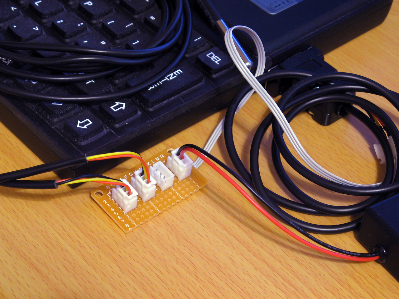
Each socket is wired in parallel to allow multiple 1-Wire devices to be connected to the Z88
To start the search, the master sends either the normal search command &F0 or the alarm/conditional search command &EC. When using the conditional search only devices that are in some sort of alarm state will respond, allowing the master to more quickly identify the devices that need attention. As we're interested in all devices we'll use the normal search command &F0.
After issuing the search command all active devices on the bus will start to report their ID, bit by bit. Each device will send each bit twice, firstly in its normal state and then again in an inverted state. Due to the open-drain nature of the bus, this allows the master to detect conflicting bit values – if all active devices have a 0 in the current bit position then the bus will read 0 then 1, if all active devices have a 1 in the current bit position then the bus will read 1 then 0 but if there is a mixture of zeroes and ones then the bus will read 0 then 0.
After this the master sends a single bit that tells the active peripheral devices which bit it has identified. If this does not match the peripheral's current bit value then the peripheral will go into an idle state and stop responding until the bus is reset again, but if it does match then the device will continue to send bits of its ID. This allows the master to walk down both branches of the binary tree when searching for device IDs when it detects a conflict, by first selecting one bit value in one iteration of the search and then the other bit value in another iteration of the search.
The full procedure for enumerating the bus is more explicitly described in the app note 1-Wire Search Algorithm, and can be implemented with the following Z80 assembly code:
.ow_conf DEFB 0 \ stores last bit conflict index
:
.ow_search
LD DE,(ow_conf):LD D,0:LD C,1:LD B,64
.ow_search_loop
PUSH BC:CALL ow_put_1:CALL ow_put_1:POP BC:RLCA:RLCA \ get bit, !bit
AND 3:JR Z,ow_search_conf \ 00 = conflict
DEC A:JR Z,ow_search_1 \ 01 = 0 bit
DEC A:JR Z,ow_search_0 \ 10 =  1 bit
SCF:RET \ report failure
.ow_search_conf
LD A,B:CP E \ how does bit index compare to last conflict
JR C,ow_search_0_conf \ 0, update current discrepancy
JR Z,ow_search_1 \ 1, no update
LD A,(HL):AND C:JR NZ,ow_search_advance \ old bit = 1, just advance
LD D,B:JR ow_search_advance \ old bit = 0, update current discrepancy
.ow_search_1:LD A,C:OR (HL):LD (HL),A:JR ow_search_advance
.ow_search_0_conf:LD D,B \ fall-through
.ow_search_0:LD A,C:CPL:AND (HL):LD (HL),A \ fall-through
.ow_search_advance
LD A,(HL):AND C:SUB C:CCF:PUSH BC:CALL ow_put_carry:POP BC \ return the ID bit
RLC C:JR NC,P%+3:INC HL \ advance mask
DJNZ ow_search_loop
LD A,D:LD (ow_conf),A
XOR A:LD (ow_buf),A:RET \ report success
A pair of BASIC wrappers can make using this search routine a bit easier:
REM Starts enumerating devices on the bus
DEFPROC_1W_SEARCH_RESET:?ow_conf=TRUE:ENDPROC
REM Searches for next device on bus. Pass search type &F0 for all devices, &EC for alarming devices. Returns TRUE if next device found
DEFFN_1W_SEARCH(A%,ID)IF ?ow_conf=0:=FALSE ELSE IF FN_1W_RESET=0:=FALSE ELSE PROC_1W_PUT(A%):H%=ID DIV256:L%=ID:CALL ow_search:=?ow_buf=0
The "reset" routine just sets the last bit conflict index to -1 (TRUE=-1) and FN_1W_SEARCH will search based on the search type (&F0 for all devices, &EC for alarming devices only), the current ID and last conflict index and will return TRUE if an ID was found or FALSE if no more IDs were found.
A snippet of code that enumerates all devices on the bus and displays their IDs is as follows:
PROC_1W_SEARCH_RESET
REPEAT F%=FN_1W_SEARCH(&F0,ID):IF F% PRINT FN_1W_ID$(ID)
UNTIL F%=FALSE
Reading temperature sensors
So far the examples have been fairly uninteresting, but we now have enough support code to do something useful with devices on a 1-Wire network. The DS18B20 temperature sensors that inspired this whole project are probably the easiest way to show how useful the 1-Wire bus can be.
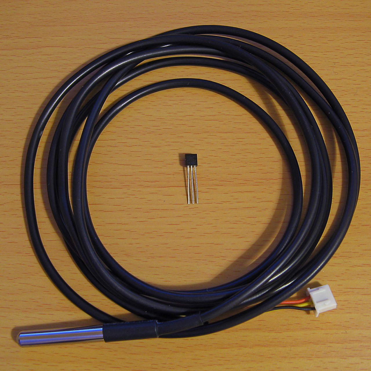
A DS18B20 temperature sensor in a TO-92 package and another in a cabled probe
The idea here will be to search for all temperature sensors on the network and to display their current temperature reading alongside their ID on the screen. The temperature conversion is initiated by sending the "Convert T" command (&44) to the desired 1-Wire devices and then waiting for at least 750ms with the bus inactive, allowing the parasitically-powered devices enough power to complete the temperature conversion, after which the temperature can be read back from the sensor's scratchpad memory.
Due to the large delay when waiting for the sensors to handle the "Convert T" command it is easiest to send the command to all devices on the network rather than to each one individually. This can be done by first sending the "Skip ROM" command (&CC) which allows the master to skip sending a 64-bit ID to the specific device it's addressing before sending the "Convert T" command (&44). The process to tell all devices to perform a temperature conversion is as follows:
IF FN_1W_RESET=FALSE PRINT "No devices found":END
REM Start temperature conversion
PROC_1W_PUT(&CC):REM Skip ROM
PROC_1W_PUT(&44):REM Convert T
T=TIME:IF INKEY(75)>TRUE REPEAT:UNTIL TIME>T+75:REM Delay 750ms
INKEY(75) is used to delay for 750ms however as this can be skipped by pressing a key a delay loop is provided as a safety measure.
After this, all of the devices on the network are enumerated as before:
REM Search for all temperature sensors on the bus and display their readings
PROC_1W_SEARCH_RESET
REPEAT F%=FN_1W_SEARCH(&F0,ID)
  IF F% PROC_1W_PRINT_TEMP(ID)
UNTIL F%=FALSE
PROC_1W_PRINT_TEMP should check to see whether the device ID corresponds to a temperature sensor (its family code, the least-significant byte, should be &28) and if so it should retrieve the temperature value and print it:
REM Print a single sensor's reading
DEFPROC_1W_PRINT_TEMP(ID)
LOCAL T
IF ID?0<>&28 ENDPROC:REM Must be a temperature sensor
T=FN_1W_READ_TEMP(ID):IF T=-999 ENDPROC:REM Read sensor and check for error
@%=&20409:PRINT MID$(FN_1W_ID$(ID),3,12);":",T;" deg C":@%=&90A
ENDPROC
@% controls the way numbers are printed – in this case it is changed to show four decimal places in a field width of 9 characters. When printing the device ID the first two characters and last two characters are stripped off as these correspond to the CRC and family code which are not particularly useful in this case.
FN_1W_READ_TEMP(ID) needs to fetch the temperature from the sensor with the specified ID or return -999 on error. A specific sensor can be addressed by first sending the match ROM command (&55) followed by the 64-bit device ID. After this the scratchpad RAM can be read by sending the "read scratchpad" command (&BE) then reading as many bytes as are required. We only need the first two, but will read nine as this includes all eight bytes of scratchpad RAM plus a CRC so we can verify the data is valid:
REM Retrieve a single sensor's reading
DEFFN_1W_READ_TEMP(ID)
LOCAL T
IF FN_1W_RESET=FALSE =-999
PROC_1W_PUT(&55):PROC_1W_PUTS(ID,8):REM Match ROM
PROC_1W_PUT(&BE):PROC_1W_GETS(SCRATCH,9):REM Read scratchpad
IF FN_1W_CRC_CHECK(SCRATCH,8)=FALSE =-999:REM Check CRC
=SCRATCH!-2DIV65536/16:REM Convert to degrees C
The final line converts the reading to °C. This is a signed 16-bit value stored in the first two bytes of the scratchpad memory. BBC BASIC's ! indirection operator reads a 32-bit value, so by reading from two bytes earlier (-2) the 16-bit temperature value is loaded into the most significant word of a 32-bit integer, and an integer divide of this by 65536 shifts this back down into the least significant word (where it should be) with the sign properly extended (so if it was a negative value before it will still be negative after the division). The value is then divided by 16 using a regular floating-point division as each unit of the temperature sensor's reported value corresponds to 1/16°C.
A complete demo program listing is shown below. Choosing option "3) Show DS18B20 temperatures" will show the temperatures of any connected DS18B20 temperature sensors.
  10 REM 1-WIRE DEMONSTRATION FOR Z88 : BEN RYVES 2023
  20 *NAME 1-Wire Demo
  30 DIM ID 7,SCRATCH 8
  40 PROC_1W_INIT
  50 :
  60 REM Main demo loop
  70 REPEAT PROC_1W_DEMO_MENU
  80   ON ERROR PRINT:END
  90   PRINT "<Press any key>";
 100   REPEAT UNTIL INKEY(0)=TRUE:IF GET
 110 UNTIL FALSE
 120 END
 130 :
 140 REM Main menu
 150 DEFPROC_1W_DEMO_MENU
 160 CLS:PRINT CHR$1;"1B";"1-Wire Demonstration for Cambridge Z88";CHR$1;"1B"
 170 ON ERROR END
 180 REPEAT
 190   PRINT '"Please choose a demo: (press ESC to exit)"
 200   PRINT "1) Enumerate devices"
 210   PRINT "2) Scan iButton tags"
 220   PRINT "3) Show DS18B20 temperatures"
 230   M%=GET-ASC"0"
 240 UNTIL M%>0 AND M%<4
 250 ON ERROR OFF
 260 PRINT
 270 ON M% PROC_1W_DEMO_LIST_DEVICES, PROC_1W_DEMO_TAG, PROC_1W_DEMO_SHOW_TEMPERATURES
 280 ENDPROC
 290 END
 300 :
 310 REM Device search demo
 320 DEFPROC_1W_DEMO_LIST_DEVICES
 330 PROC_1W_SEARCH_RESET
 340 REPEAT F%=FN_1W_SEARCH(&F0,ID):IF F% PRINT FN_1W_ID$(ID)
 350 UNTIL F%=FALSE:ENDPROC
 360 :
 370 REM ID tag scanning demo
 380 DEFPROC_1W_DEMO_TAG
 390 ON ERROR GOTO 50
 400 PRINT "Tap a tag on the reader (press ESC to exit)"
 410 REPEAT
 420   REPEAT UNTIL FN_1W_RESET:REM Wait for device to be present
 430   PROC_1W_PUT(&33):REM Read ROM
 440   PROC_1W_GETS(ID,8):REM Fetch ID
 450   IF FN_1W_CRC_CHECK(ID,7) AND ID?0=1 VDU 7:PRINT "Detected ";FN_1W_ID$(ID);" at ";TIME$:REM Print if valid
 460   REPEAT UNTIL FN_1W_RESET=FALSE:REM Wait for device to be disconnected
 470 UNTIL FALSE
 480 ENDPROC
 490 :
 500 REM Temperature demo
 510 DEFPROC_1W_DEMO_SHOW_TEMPERATURES
 520 IF FN_1W_RESET=FALSE PRINT "No devices found":ENDPROC
 530 REM Start temperature conversion
 540 PROC_1W_PUT(&CC):REM Skip ROM
 550 PROC_1W_PUT(&44):REM Convert T
 560 T=TIME:IF INKEY(75)>TRUE REPEAT:UNTIL TIME>T+75:REM Delay 750ms
 570 REM Search for all temperature sensors on the bus and display their readings
 580 PROC_1W_SEARCH_RESET
 590 REPEAT F%=FN_1W_SEARCH(&F0,ID)
 600   IF F% PROC_1W_PRINT_TEMP(ID)
 610 UNTIL F%=FALSE
 620 ENDPROC
 630 REM Print a single sensor's reading
 640 DEFPROC_1W_PRINT_TEMP(ID)
 650 LOCAL T
 660 IF ID?0<>&28 ENDPROC:REM Must be a temperature sensor
 670 T=FN_1W_READ_TEMP(ID):IF T=-999 ENDPROC:REM Read sensor and check for error
 680 @%=&20409:PRINT MID$(FN_1W_ID$(ID),3,12);":",T;" deg C":@%=&90A
 690 ENDPROC
 700 REM Retrieve a single sensor's reading
 710 DEFFN_1W_READ_TEMP(ID)
 720 LOCAL T
 730 IF FN_1W_RESET=FALSE =-999
 740 PROC_1W_PUT(&55):PROC_1W_PUTS(ID,8):REM Match ROM
 750 PROC_1W_PUT(&BE):PROC_1W_GETS(SCRATCH,9):REM Read scratchpad
 760 IF FN_1W_CRC_CHECK(SCRATCH,8)=FALSE =-999:REM Check CRC
 770 =SCRATCH!-2DIV65536/16:REM Convert to degrees C
 780 :
 790 REM 1-WIRE ROUTINES
 800 END
 810 DEFPROC_1W_INIT
 820 ow_code_size=294:DIM ow_code ow_code_size-1
 830 RXE=&E1:M_RXERXD=&10
 840 TXC=&E4:M_TXCITX=&08
 850 SC=&400
 860 FOR opt=0 TO 2 STEP 2
 870   P%=ow_code
 880   [OPT opt
 890   .ow_buf DEFB 0 \ temporary transfer buffer
 900   .ow_conf DEFB 0 \ stores last bit conflict index
 910   :
 920   .ow_reset
 930   IN A,(RXE):AND M_RXERXD:CP M_RXERXD:SBC A,A:LD (ow_buf),A:RET NZ \ check bus is idle
 940   DI:LD A,(SC+TXC):OR M_TXCITX:OUT (TXC),A \ hold bus low
 950   LD B,120:DJNZ P% \ delay
 960   AND NOT M_TXCITX:OUT (TXC),A \ release bus
 970   LD B,18:DJNZ P% \ delay
 980   IN A,(RXE):AND M_RXERXD:CP M_RXERXD:CCF:SBC A,A:LD (ow_buf),A \ sample presence
 990   LD B,100:DJNZ P% \ delay
1000   EI:RET
1010   :
1020   .ow_put_carry
1030   JR C,ow_put_1 \ fall-through
1040   :
1050   .ow_put_0
1060   DI
1070   LD A,(SC+TXC):OR M_TXCITX:OUT (TXC),A \ hold bus low
1080   LD B,15:DJNZ P% \ delay
1090   AND NOT M_TXCITX:OUT (TXC),A \ release bus
1100   NOP \ delay
1110   EI:RET
1120   :
1130   .ow_put_1
1140   DI
1150   LD A,(SC+TXC):OR M_TXCITX:OUT (TXC),A \ hold bus low
1160   NOP \ delay
1170   AND NOT M_TXCITX:OUT (TXC),A \ release bus
1180   PUSH HL:POP HL \ delay
1190   IN A,(RXE):AND M_RXERXD:SUB M_RXERXD:CCF \ sample bit
1200   LD A,(ow_buf):RRA:LD (ow_buf),A \ store bit
1210   LD B,7:DJNZ P% \ delay
1220   EI:RET
1230   :
1240   .ow_put_byte
1250   LD C,A:LD B,8 \ value to send in C, send 8 bits
1260   .ow_put_loop
1270   SRL C:PUSH BC:CALL ow_put_carry:POP BC \ shift and send single bit
1280   DJNZ ow_put_loop \ loop
1290   RET
1300   :
1310   .ow_put_bytes
1320   LD A,B:OR C:RET Z:DEC BC \ have we finished?
1330   LD A,(HL):INC HL \ fetch
1340   PUSH BC:CALL ow_put_byte:POP BC:JR ow_put_bytes \ send and loop
1350   :
1360   .ow_get_byte
1370   LD B,8 \ 8 bits to receive
1380   .ow_get_loop
1390   PUSH BC:CALL ow_put_1:POP BC \ receive single bit
1400   DJNZ ow_get_loop \ loop
1410   LD A,(ow_buf):RET \ store
1420   :
1430   .ow_get_bytes
1440   LD A,B:OR C:RET Z:DEC BC \ have we finished?
1450   PUSH BC:CALL ow_get_byte:POP BC \ get a byte
1460   LD (HL),A:INC HL:JR ow_get_bytes \ store and loop
1470   :
1480   .ow_search
1490   LD DE,(ow_conf):LD D,0:LD C,1:LD B,64
1500   .ow_search_loop
1510   PUSH BC:CALL ow_put_1:CALL ow_put_1:POP BC:RLCA:RLCA \ get bit, !bit
1520   AND 3:JR Z,ow_search_conf \ 00 = conflict
1530   DEC A:JR Z,ow_search_1 \ 01 = 0 bit
1540   DEC A:JR Z,ow_search_0 \ 10 =  1 bit
1550   SCF:RET \ report failure
1560   .ow_search_conf
1570   LD A,B:CP E \ how does bit index compare to last conflict
1580   JR C,ow_search_0_conf \ 0, update current discrepancy
1590   JR Z,ow_search_1 \ 1, no update
1600   LD A,(HL):AND C:JR NZ,ow_search_advance \ old bit = 1, just advance
1610   LD D,B:JR ow_search_advance \ old bit = 0, update current discrepancy
1620   .ow_search_1:LD A,C:OR (HL):LD (HL),A:JR ow_search_advance
1630   .ow_search_0_conf:LD D,B \ fall-through
1640   .ow_search_0:LD A,C:CPL:AND (HL):LD (HL),A \ fall-through
1650   .ow_search_advance
1660   LD A,(HL):AND C:SUB C:CCF:PUSH BC:CALL ow_put_carry:POP BC \ return the ID bit
1670   RLC C:JR NC,P%+3:INC HL \ advance mask
1680   DJNZ ow_search_loop
1690   LD A,D:LD (ow_conf),A
1700   XOR A:LD (ow_buf),A:RET \ report success
1710   :
1720   .ow_crc
1730   LD B,8:LD DE,(ow_buf):LD D,A \ E = accumulated CRC, D = value to add
1740   .ow_crc_loop
1750   LD A,E:XOR D:SRL D:SRL A:JR C,ow_crc_odd \ XOR and shift bits
1760   SRL E:DJNZ ow_crc_loop:LD A,E:LD (ow_buf),A:RET \ even CRC value
1770   .ow_crc_odd:SRL E:LD A,&8C:XOR E:LD E,A:DJNZ ow_crc_loop:LD (ow_buf),A:RET \ odd CRC value
1780   :
1790   .ow_crc_block
1800   XOR A:LD (ow_buf),A \ reset CRC
1810   .ow_crc_block_loop
1820   LD A,B:OR C:LD A,(ow_buf):RET Z:DEC BC \ have we finished?
1830   LD A,(HL):INC HL:PUSH BC:CALL ow_crc:POP BC:JR ow_crc_block_loop \ update CRC
1840   ]
1850 NEXT
1860 IF P%-ow_code<>ow_code_size PRINT"Code size: "P%-ow_code:END
1870 ENDPROC
1880 :
1890 REM Resets bus, retuns TRUE if any devices are present
1900 DEFFN_1W_RESET:CALL ow_reset:=?ow_buf=0
1910 REM Transmits a single byte
1920 DEFPROC_1W_PUT(A%)CALL ow_put_byte:ENDPROC
1930 REM Transmits a block of bytes
1940 DEFPROC_1W_PUTS(L%,C%)LOCAL H%,B%:H%=L%DIV256:B%=C%DIV256:CALL ow_put_bytes:ENDPROC
1950 REM Receives a single byte
1960 DEFFN_1W_GET:CALL ow_get_byte:=?ow_buf
1970 REM Receives a block of bytes
1980 DEFPROC_1W_GETS(L%,C%)LOCAL H%,B%:H%=L%DIV256:B%=C%DIV256:CALL ow_get_bytes:ENDPROC
1990 :
2000 REM Starts enumerating devices on the bus
2010 DEFPROC_1W_SEARCH_RESET:?ow_conf=TRUE:ENDPROC
2020 REM Searches for next device on bus. Pass search type &F0 for all devices, &EC for alarming devices. Returns TRUE if next device found
2030 DEFFN_1W_SEARCH(A%,ID)IF ?ow_conf=0:=FALSE ELSE IF FN_1W_RESET=0:=FALSE ELSE PROC_1W_PUT(A%):H%=ID DIV256:L%=ID:CALL ow_search:=?ow_buf=0
2040 :
2050 REM Converts ID bytes into string
2060 DEFFN_1W_ID$(ID)LOCAL I%:S$="":FOR I%=7 TO 0 STEP -1:IF ID?I%>15:S$=S$+STR$~(ID?I%):NEXT:=S$:ELSE:S$=S$+"0"+STR$~(ID?I%):NEXT:=S$
2070 REM Converts string into ID bytes
2080 DEFPROC_1W_ID$(ID,ID$)LOCAL I%:FOR I%=0 TO 7:ID?I%=EVAL("&"+MID$(ID$,15-I%*2,2)):NEXT:ENDPROC
2090 :
2100 REM Calculates the CRC of a block of data
2110 DEFFN_1W_CRC(L%,C%)LOCAL H%,B%:H%=L% DIV256:B%=C%DIV256:CALL ow_crc_block:=?ow_buf
2120 REM Checks if a CRC at the end of a block of data matches
2130 DEFFN_1W_CRC_CHECK(L%,C%)=FN_1W_CRC(L%,C%)=(L%?C%)
Temperature logger
All of this can be put together into a program that logs the temperature from any connected sensors to a CSV file on the Z88. The main loop can look similar to the one above that searches for and displays the temperature readings for any connected DS18B20 sensors, however it will instead call a PROC_1W_LOG_TEMP procedure that handles logging the data to a file instead of printing it on the display:
REM Log a single sensor's reading
DEFPROC_1W_LOG_TEMP(ID)
LOCAL T
IF ID?0<>&28 ENDPROC:REM Must be a temperature sensor
T=FN_1W_READ_TEMP(ID):IF T=-999 ENDPROC:REM Read sensor and check for error
ENTRY$=FN_DATETIME$(TIME$)+","+STR$T:REM Timestamp and temperature reading
ID$=MID$(FN_1W_ID$(ID),3,12):REM ID without CRC and family code
CSV$=ID$+".CSV":REM Name of CSV file
C=OPENUP CSV$:REM Open the CSV for update
IF C=FALSE C=OPENOUT CSV$:PRINT#C,"Time,"+ID$:REM Create new CSV if required
PTR#C=EXT#C:PRINT#C,ENTRY$:REM Write entry to end of CSV
CLOSE#C:REM Close the CSV
PRINT CSV$,ENTRY$:REM Display on screen
ENDPROC
The procedure will fetch the value from the sensor and then turn the ID into a CSV filename by stripping off the CRC and family code and appending ".CSV". It will then try to open the existing file, and if one doesn't exist it will create a new one and write the column headers to it. It will then seek to the end of the file and append the timestamp and the temperature reading.
One further complication is that to make handling the CSV a bit easier, the timestamp is converted from the format returned by BBC BASIC's TIME$ function into "YYYY-MM-DD hh:mm:ss" format. This is handled by the following three functions, FN_DATE (which extracts and reformats the date component into YYYY-MM-DD format), FN_TIME (which extracts the time component into hh:mm:ss format) and FN_DATETIME which glues the date and time back together with a space in the middle:
REM Date formatting routines
DEF FN_DATE$(T$)
LOCAL C%,I%,J%,V%,R$
R$="":I%=1
FOR C%=0 TO 3 J%=INSTR(MID$(T$,I%)," ")
  IF C%=2 V%=1+INSTR("JanFebMarAprMayJunJulAugSepOctNovDec",MID$(T$,I%,3))DIV3 ELSE V%=VAL(MID$(T$,I%,J%-1))
  IF C%>1 R$="-"+R$
  IF C% R$=STR$(V%)+R$ IF V%<10 R$="0"+R$
  I%=I%+J%
NEXT
=R$
DEF FN_TIME$(T$) =MID$(T$,LEN(T$)-7)
DEF FN_DATETIME$(T$) =FN_DATE$(T$)+" "+FN_TIME$(T$)
One way to make this logging program more useful would be to get the computer to run it periodically (e.g. once per minute). The Z88's "Alarm" feature can execute a command whenever the alarm goes off and you can schedule recurring alarms so this sounds like an ideal starting point! When the program has run it would also be handy for the computer to switch itself off again. There is an OS call for this, OS_Off, which can be invoked from BASIC as follows:
REM SWITCH OFF ROUTINES
DEFPROC_SWITCH_OFF_INIT
switch_off_size=15:DIM switch_off switch_off_size-1
P%=switch_off
[OPT 2
LD HL,0:ADD HL,SP:LD SP,(&1FFE):PUSH HL
RST &20:DEFW &EC06:REM OS_Off
POP HL:LD SP,HL:RET:]
ENDPROC
DEFPROC_SWITCH_OFF:CALL switch_off:ENDPROC
As with the 1-Wire assembly routines you must first call an initialisation procedure (PROC_SWITCH_OFF_INIT) to assemble the routine before calling it with PROC_SWITCH_OFF. The actual OS_Off call is the RST &20H:DEFW &EC06 in the middle of all that. Unfortunately, OS calls tend to involve some memory paging and in the process BBC BASIC's RAM gets swapped out and when the OS routine tries to return it jumps back into some different memory – the computer certainly switches off, but then it soft resets instead of coming back on properly. This is why there's some additional boilerplate code around the OS call to move the stack pointer into a safe region of memory so the routine can return properly.
The complete temperature-logging program is now shown below:
  10 REM 1-WIRE TEMPERATURE LOGGER : BEN RYVES 2023
  20 *NAME 1-Wire Temperature Logger
  30 REPEAT UNTIL INKEY(0)=TRUE:REM Flush keyboard
  40 DIM ID 7,SCRATCH 8
  50 PROC_1W_INIT
  60 PROC_SWITCH_OFF_INIT
  70 REM Reset 1-Wire bus and check that at least one device is present
  80 IF FN_1W_RESET=FALSE PROC_SWITCH_OFF:END
  90 REM Start temperature conversion
 100 PROC_1W_PUT(&CC):REM Skip ROM
 110 PROC_1W_PUT(&44):REM Convert T
 120 T=TIME:IF INKEY(75)>TRUE REPEAT:UNTIL TIME>T+75:REM Delay 750ms
 130 REM Search for all temperature sensors on the bus and log their readings
 140 PROC_1W_SEARCH_RESET
 150 REPEAT F%=FN_1W_SEARCH(&F0,ID):IF F% PROC_1W_LOG_TEMP(ID)
 160 UNTIL F%=FALSE
 170 REM Switch the computer off
 180 PROC_SWITCH_OFF
 190 END
 200 :
 210 REM Log a single sensor's reading
 220 DEFPROC_1W_LOG_TEMP(ID)
 230 LOCAL T
 240 IF ID?0<>&28 ENDPROC:REM Must be a temperature sensor
 250 T=FN_1W_READ_TEMP(ID):IF T=-999 ENDPROC:REM Read sensor and check for error
 260 ENTRY$=FN_DATETIME$(TIME$)+","+STR$T:REM Timestamp and temperature reading
 270 ID$=MID$(FN_1W_ID$(ID),3,12):REM ID without CRC and family code
 280 CSV$=ID$+".CSV":REM Name of CSV file
 290 C=OPENUP CSV$:REM Open the CSV for update
 300 IF C=FALSE C=OPENOUT CSV$:PRINT#C,"Time,"+ID$:REM Create new CSV if required
 310 PTR#C=EXT#C:PRINT#C,ENTRY$:REM Write entry to end of CSV
 320 CLOSE#C:REM Close the CSV
 330 PRINT CSV$,ENTRY$:REM Display on screen
 340 ENDPROC
 350 REM Retrieve a single sensor's reading
 360 DEFFN_1W_READ_TEMP(ID)
 370 LOCAL T
 380 IF FN_1W_RESET=FALSE =-999
 390 PROC_1W_PUT(&55):PROC_1W_PUTS(ID,8):REM Match ROM
 400 PROC_1W_PUT(&BE):PROC_1W_GETS(SCRATCH,9):REM Read scratchpad
 410 IF FN_1W_CRC_CHECK(SCRATCH,8)=FALSE =-999:REM Check CRC
 420 =SCRATCH!-2DIV65536/16:REM Convert to degrees C
 430 :
 440 REM Date formatting routines
 450 DEF FN_DATE$(T$)
 460 LOCAL C%,I%,J%,V%,R$
 470 R$="":I%=1
 480 FOR C%=0 TO 3 J%=INSTR(MID$(T$,I%)," ")
 490   IF C%=2 V%=1+INSTR("JanFebMarAprMayJunJulAugSepOctNovDec",MID$(T$,I%,3))DIV3 ELSE V%=VAL(MID$(T$,I%,J%-1))
 500   IF C%>1 R$="-"+R$
 510   IF C% R$=STR$(V%)+R$ IF V%<10 R$="0"+R$
 520   I%=I%+J%
 530 NEXT
 540 =R$
 550 DEF FN_TIME$(T$) =MID$(T$,LEN(T$)-7)
 560 DEF FN_DATETIME$(T$) =FN_DATE$(T$)+" "+FN_TIME$(T$)
 570 :
 580 REM SWITCH OFF ROUTINES
 590 DEFPROC_SWITCH_OFF_INIT
 600 switch_off_size=15:DIM switch_off switch_off_size-1
 610 P%=switch_off
 620 [OPT 2
 630 LD HL,0:ADD HL,SP:LD SP,(&1FFE):PUSH HL
 640 RST &20:DEFW &EC06
 650 POP HL:LD SP,HL:RET:]
 660 ENDPROC
 670 DEFPROC_SWITCH_OFF:CALL switch_off:ENDPROC
 680 :
 690 REM 1-WIRE ROUTINES
 700 END
 710 DEFPROC_1W_INIT
 720 ow_code_size=294:DIM ow_code ow_code_size-1
 730 RXE=&E1:M_RXERXD=&10
 740 TXC=&E4:M_TXCITX=&08
 750 SC=&400
 760 FOR opt=0 TO 2 STEP 2
 770   P%=ow_code
 780   [OPT opt
 790   .ow_buf DEFB 0 \ temporary transfer buffer
 800   .ow_conf DEFB 0 \ stores last bit conflict index
 810   :
 820   .ow_reset
 830   IN A,(RXE):AND M_RXERXD:CP M_RXERXD:SBC A,A:LD (ow_buf),A:RET NZ \ check bus is idle
 840   DI:LD A,(SC+TXC):OR M_TXCITX:OUT (TXC),A \ hold bus low
 850   LD B,120:DJNZ P% \ delay
 860   AND NOT M_TXCITX:OUT (TXC),A \ release bus
 870   LD B,18:DJNZ P% \ delay
 880   IN A,(RXE):AND M_RXERXD:CP M_RXERXD:CCF:SBC A,A:LD (ow_buf),A \ sample presence
 890   LD B,100:DJNZ P% \ delay
 900   EI:RET
 910   :
 920   .ow_put_carry
 930   JR C,ow_put_1 \ fall-through
 940   :
 950   .ow_put_0
 960   DI
 970   LD A,(SC+TXC):OR M_TXCITX:OUT (TXC),A \ hold bus low
 980   LD B,15:DJNZ P% \ delay
 990   AND NOT M_TXCITX:OUT (TXC),A \ release bus
1000   NOP \ delay
1010   EI:RET
1020   :
1030   .ow_put_1
1040   DI
1050   LD A,(SC+TXC):OR M_TXCITX:OUT (TXC),A \ hold bus low
1060   NOP \ delay
1070   AND NOT M_TXCITX:OUT (TXC),A \ release bus
1080   PUSH HL:POP HL \ delay
1090   IN A,(RXE):AND M_RXERXD:SUB M_RXERXD:CCF \ sample bit
1100   LD A,(ow_buf):RRA:LD (ow_buf),A \ store bit
1110   LD B,7:DJNZ P% \ delay
1120   EI:RET
1130   :
1140   .ow_put_byte
1150   LD C,A:LD B,8 \ value to send in C, send 8 bits
1160   .ow_put_loop
1170   SRL C:PUSH BC:CALL ow_put_carry:POP BC \ shift and send single bit
1180   DJNZ ow_put_loop \ loop
1190   RET
1200   :
1210   .ow_put_bytes
1220   LD A,B:OR C:RET Z:DEC BC \ have we finished?
1230   LD A,(HL):INC HL \ fetch
1240   PUSH BC:CALL ow_put_byte:POP BC:JR ow_put_bytes \ send and loop
1250   :
1260   .ow_get_byte
1270   LD B,8 \ 8 bits to receive
1280   .ow_get_loop
1290   PUSH BC:CALL ow_put_1:POP BC \ receive single bit
1300   DJNZ ow_get_loop \ loop
1310   LD A,(ow_buf):RET \ store
1320   :
1330   .ow_get_bytes
1340   LD A,B:OR C:RET Z:DEC BC \ have we finished?
1350   PUSH BC:CALL ow_get_byte:POP BC \ get a byte
1360   LD (HL),A:INC HL:JR ow_get_bytes \ store and loop
1370   :
1380   .ow_search
1390   LD DE,(ow_conf):LD D,0:LD C,1:LD B,64
1400   .ow_search_loop
1410   PUSH BC:CALL ow_put_1:CALL ow_put_1:POP BC:RLCA:RLCA \ get bit, !bit
1420   AND 3:JR Z,ow_search_conf \ 00 = conflict
1430   DEC A:JR Z,ow_search_1 \ 01 = 0 bit
1440   DEC A:JR Z,ow_search_0 \ 10 =  1 bit
1450   SCF:RET \ report failure
1460   .ow_search_conf
1470   LD A,B:CP E \ how does bit index compare to last conflict
1480   JR C,ow_search_0_conf \ 0, update current discrepancy
1490   JR Z,ow_search_1 \ 1, no update
1500   LD A,(HL):AND C:JR NZ,ow_search_advance \ old bit = 1, just advance
1510   LD D,B:JR ow_search_advance \ old bit = 0, update current discrepancy
1520   .ow_search_1:LD A,C:OR (HL):LD (HL),A:JR ow_search_advance
1530   .ow_search_0_conf:LD D,B \ fall-through
1540   .ow_search_0:LD A,C:CPL:AND (HL):LD (HL),A \ fall-through
1550   .ow_search_advance
1560   LD A,(HL):AND C:SUB C:CCF:PUSH BC:CALL ow_put_carry:POP BC \ return the ID bit
1570   RLC C:JR NC,P%+3:INC HL \ advance mask
1580   DJNZ ow_search_loop
1590   LD A,D:LD (ow_conf),A
1600   XOR A:LD (ow_buf),A:RET \ report success
1610   :
1620   .ow_crc
1630   LD B,8:LD DE,(ow_buf):LD D,A \ E = accumulated CRC, D = value to add
1640   .ow_crc_loop
1650   LD A,E:XOR D:SRL D:SRL A:JR C,ow_crc_odd \ XOR and shift bits
1660   SRL E:DJNZ ow_crc_loop:LD A,E:LD (ow_buf),A:RET \ even CRC value
1670   .ow_crc_odd:SRL E:LD A,&8C:XOR E:LD E,A:DJNZ ow_crc_loop:LD (ow_buf),A:RET \ odd CRC value
1680   :
1690   .ow_crc_block
1700   XOR A:LD (ow_buf),A \ reset CRC
1710   .ow_crc_block_loop
1720   LD A,B:OR C:LD A,(ow_buf):RET Z:DEC BC \ have we finished?
1730   LD A,(HL):INC HL:PUSH BC:CALL ow_crc:POP BC:JR ow_crc_block_loop \ update CRC
1740   ]
1750 NEXT
1760 IF P%-ow_code<>ow_code_size PRINT"Code size: "P%-ow_code:END
1770 ENDPROC
1780 :
1790 REM Resets bus, retuns TRUE if any devices are present
1800 DEFFN_1W_RESET:CALL ow_reset:=?ow_buf=0
1810 REM Transmits a single byte
1820 DEFPROC_1W_PUT(A%)CALL ow_put_byte:ENDPROC
1830 REM Transmits a block of bytes
1840 DEFPROC_1W_PUTS(L%,C%)LOCAL H%,B%:H%=L%DIV256:B%=C%DIV256:CALL ow_put_bytes:ENDPROC
1850 REM Receives a single byte
1860 DEFFN_1W_GET:CALL ow_get_byte:=?ow_buf
1870 REM Receives a block of bytes
1880 DEFPROC_1W_GETS(L%,C%)LOCAL H%,B%:H%=L%DIV256:B%=C%DIV256:CALL ow_get_bytes:ENDPROC
1890 :
1900 REM Starts enumerating devices on the bus
1910 DEFPROC_1W_SEARCH_RESET:?ow_conf=TRUE:ENDPROC
1920 REM Searches for next device on bus. Pass search type &F0 for all devices, &EC for alarming devices. Returns TRUE if next device found
1930 DEFFN_1W_SEARCH(A%,ID)IF ?ow_conf=0:=FALSE ELSE IF FN_1W_RESET=0:=FALSE ELSE PROC_1W_PUT(A%):H%=ID DIV256:L%=ID:CALL ow_search:=?ow_buf=0
1940 :
1950 REM Converts ID bytes into string
1960 DEFFN_1W_ID$(ID)LOCAL I%:S$="":FOR I%=7 TO 0 STEP -1:IF ID?I%>15:S$=S$+STR$~(ID?I%):NEXT:=S$:ELSE:S$=S$+"0"+STR$~(ID?I%):NEXT:=S$
1970 REM Converts string into ID bytes
1980 DEFPROC_1W_ID$(ID,ID$)LOCAL I%:FOR I%=0 TO 7:ID?I%=EVAL("&"+MID$(ID$,15-I%*2,2)):NEXT:ENDPROC
1990 :
2000 REM Calculates the CRC of a block of data
2010 DEFFN_1W_CRC(L%,C%)LOCAL H%,B%:H%=L% DIV256:B%=C%DIV256:CALL ow_crc_block:=?ow_buf
2020 REM Checks if a CRC at the end of a block of data matches
2030 DEFFN_1W_CRC_CHECK(L%,C%)=FN_1W_CRC(L%,C%)=(L%?C%)
When run this will log the temperatures of all connected sensors to CSV files as described above then switch the Z88 off. The "Alarm" popdown can be used to set up an alarm that runs the program once per minute (or at any other desired interval) by choosing an alarm type of "execute". This will effectively type in the supplied command, and so by setting it to #BRUN"TEMPLOG.BBC"~E it will press □+B to switch to BASIC (#B), type in RUN"TEMPLOG" and then press Enter (~E).

Setting up the alarm this way each time can be a bit tedious, so to make things easier here's a CLI file that can be used to set up the alarm:
.;Set up temperature logging alarm
#A
~R~E
~D~D
##BRUN"TEMPLOG.BBC"~~E
~D
~D~R~D~R~S~U~S~U~R~D
This contains keystrokes in a similar fashion to the "command" field in the alarm settings and can be "executed" from the Z88's Filer; here #A presses □+A to enter the Alarm pop-down, ~R, ~D or ~U move the cursor right, down or up and where we need to type literal # or ~ signs they are doubled up (## or ~~). This will enter all of the required details to set up an alarm that will run the task once per minute forever, at which point they can be adjusted if required (e.g. to change the interval). Pressing Enter will create the alarm, and leaving the Alarm popdown will set it in motion. To finish data collection the Z88 can be switched back on as normal for the alarm to be cleared.
The only other point of note is that I found that the computer seemed to get a bit "gummed up" with queued keypresses. This could be because it never sits idle after handling the alarm; it runs the BASIC program then switches the computer off, waiting for the next alarm to be run. This is why a simple loop to flush the keyboard buffer occurs at the start of the program, and the computer seems much happier for it.
The temperature logs in the CSV files can be used to generate a chart like the following:
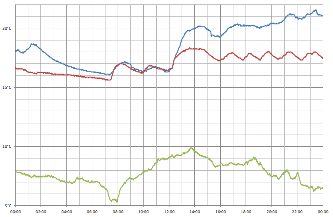
I captured data from three sensors over a 24 hour period; one outside (green line), one in my bedroom (red line) and one in my office (blue line). You can see how the central heating kicks in at 07:30, and I turned it up a little after 12:00. During the day the temperature in the bedroom moves up and down as the heating switches on and off, but the temperature in the office appears to be more consistent and a bit higher – the sensor is near where I am sitting and my desktop computer, which is likely contributing some heat.
Conclusion
What was originally intended to be a quick project to make use a couple of electronic components I had been sent in error soon turned into what I thought was an interesting demonstration of what can be done with the Cambridge Z88 using its stock software and some very basic additional hardware, further cementing my appreciation for the well-designed device.
The files accompanying this post can be downloaded below:
- ONEWIRE.BBC – 1-Wire demonstration program.
- TEMPLOG.BBC and TEMPLOG.CLI – Temperature logging program and CLI file to set up the alarm.
- templogs.zip and templogs.xlsx – Sample data captured by the temperature logging program.