Booting CP/M 3 from an SD card
Wednesday, 23rd June 2010
Up to this point I have been running CP/M 2.2 on the Z80 computer. CP/M 3 adds a number of useful features, including the following:
- Support for more than 64KB RAM via banked memory.
- Standardised access to real-time clock for file date and time stamping.
- Improved text entry on the command-line when using the memory-banked version, such as the ability to move the cursor when editing and recall the previously entered line.
- Support for disks with physical sectors larger than the default record size of 128 bytes.
Switching to a banked memory system would require some new hardware in the form of a memory management unit so I have stuck with the simpler non-banked system for the time being. Support for physical disk sectors larger than 128 bytes is more interesting (SD cards use 512 byte "blocks") and real-time clocks are always useful so I have started working on updating to CP/M 3.
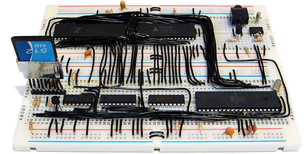
Z80 computer with new SD card slot (bottom left) and real-time clock (top right)
CP/M consists of three main pieces of software:
- A BIOS which exposes a small number of routines to perform primitive, hardware-specific operations (e.g. output a character to the console, read a raw sector from a disk, check if a key has been pressed).
- The BDOS which provides the main API for transient programs (e.g. read a complete line of input from the console, create a file, read a record from a file).
- The CCP, or console command processor, which provides the main user interface for loading and running other programs or performing some basic tasks via its built-in commands. This would be analogous to COMMAND.COM on DOS.
When working with CP/M 2.2 I had source files for these three pieces of software, so I just needed to implement the 17 BIOS functions, reassemble the three files to fixed addresses in memory and load them to these fixed addresses using the AVR when booting the computer. These three files were stored in the lower 8KB of the flash memory chip and were not accessible from within CP/M itself.
CP/M 3 proved to be a bit more of a challenge, as it is loaded slightly differently. The CCP is stored as a regular file named CCP.COM on the floppy disk you're booting from, so only the BIOS and BDOS need to be loaded from their hiding place at the start of the boot disk. These two pieces of software are merged into a single file named CPM3.SYS by a CP/M utility named GENCPM. To get this utility to work I needed to provide GENCPM with a hardware-specific BIOS3.SPR file that implemented the 31 BIOS routines. Fortunately, a file named BIOSKRNL.ASM is provided that implements most of the boilerplate code involved with writing a BIOS (you still have to provide the hardware-specific routines yourself, but your task is made much easier by following the template) so I just needed to recompile that for a non-banked system and link it with my handful of hardware-specific routines.
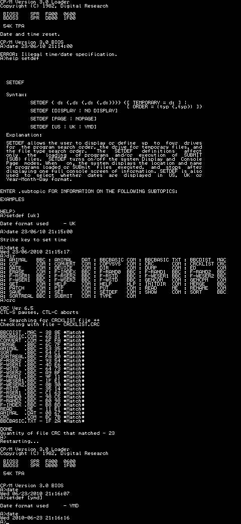
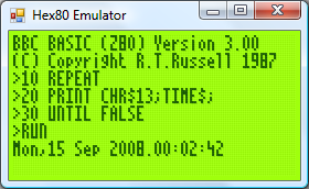
Ideally, CPM3.SYS would be stored on the regular file system with CCP.COM and the hidden boot loader would load CPM3.SYS for you. CP/M 3 does provide a small boot loader for this purpose (aptly named CPMLDR) which employs a cut-down BDOS and BIOS to load CPM3.SYS from the file system into memory for you. I haven't been able to get it to work, though, so I currently parse and load CPM3.SYS using some C code on the AVR. This works well enough for the time being, as can be seen in the above output generated by the computer when testing the real-time clock.
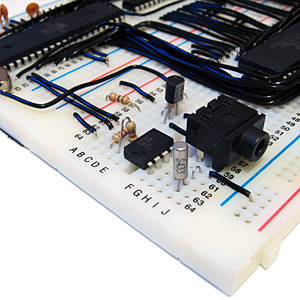
The time and date is maintained by a DS1307, an inexpensive eight-pin real-time clock and calendar chip that is shown in the middle of the above photograph. It is accessed over the I2C bus using a protocol that is natively supported by the AVR hardware. It uses binary-coded decimal to represent dates and times, which corresponds nicely to the time format used by CP/M; however, CP/M represents dates as a 16-bit integer counting the number of days since the 31st December 1977. I have used the algorithms on this website to convert dates to and from this format and the individual components.
The only downside of the DS1307 is that it only stores a two-digit year number, not the four digits one would hope for. This means that the century is discarded when setting the real-time clock, allowing for you to set a date that is then retrieved differently (truncated to the range 1930..2029). I haven't thought of a suitable solution to this problem just yet. I could use the AVR to act as the real-time clock, but I would then lose the advantage of the DS1307's battery backup that kicks in when the main power supply is removed.
The state of the DS1307 is effectively random at power-up. One of the first things the computer does when booting is to read the current date and time and check that all fields are within range. If not it resets them to midnight on the 1st January 1978 and displays a message to indicate that it has done so.
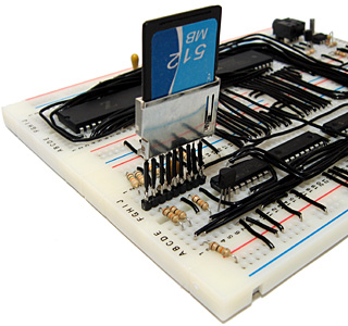
The SD card has been a bit of a headache to get working and though it currently only supports reading, not writing, it should hopefully be a useful addition to the computer. Rather than the previous arrangement of series rectifier diodes to drop the supply voltage and zener diodes to protect the inputs I'm using a dedicated 3.3V regulator to power the card and resistor voltage dividers to drop the 5V logic signals to around 3V (the closest I could get to 3.3V with the resistors I had to hand). I'm using the disk image from the old 512KB flash chip and treating the card as having 128 byte sectors so the arrangement is no more capable than before and in some cases quite a lot slower (reading a 128 byte record now entails reading a whole 512 byte block from the card then returning the desired 128 byte range within that block) but it seems to be as reliable as it used to be at least. SD cards append a CRC16 checksum when transferring data blocks so I can hopefully detect errors more easily and their on-board flash memory controller should perform wear-levelling, prolonging the life of the card.
To write the disk image to the card I used HxD which makes the job as easy as copy and paste. One problem I did have is that it displayed an "Access denied" error when attempting to write data, which I assume to be because something in Windows was using the card at the same time as HxD. I knocked together a short program for the AVR that wrote junk to the first block of the card, the result being that Windows no longer recognised the card's file system and HxD managed to write the data to the disk with no further problems.
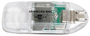
Sockets for regular SD cards seem to be relatively expensive for what they are, but the above SD card reader cost a pound (what else?) from Poundland. A bit of work with a soldering iron and some desoldering tools yielded some useful components:
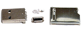
The crystal is unmarked and I'm hardly short of LEDs but the USB A connector could be a good way to reduce the size of a project that plugs into a USB port (USB B connectors are rather bulky) and the SD card slot works brilliantly for my needs here. There are cheaper and nastier ways to add an SD card slot to your project, but something like this feels more robust and has the advantage of reporting the state of the card's write protection switch.
Times, backlights and off-page calls
Sunday, 14th September 2008
Dates, times and backlights
I'm using a DS1307 real-time clock to provide the computer with real-time date and time functions. It's a great little chip - all it needs is power, two lines for I2C communications, a 32768Hz crystal between two pins and a back-up battery to keep it ticking when main power is removed and it's happy. That accounts for seven pins; the last remaining pin can be used as a one-bit output (you can set it to a high or low state in software) or it can be configured to output a square wave at 1Hz, ~4kHz, ~8kHz or ~32kHz.
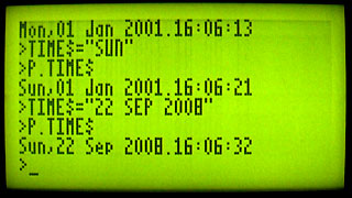
BBC BASIC can access the clock via the TIME$ pseudo-variable. This string variable returns the date and time in the format Sun,14 Sep 2008.15:20:00, and you can set the clock by assigning to the variable. When setting the clock you can specify either the date, the time, or both. Parsing the string has been an interesting exercise in Z80 programming, as it's not something I've ever attempted without regular expressions before!
The only hardware modification since last time is a very poorly implemented software control of the backlight. The fifth bit of the control port specifies whether the backlight is on or off, and it can be toggled with the *BACKLIGHT command. I say "poorly implemented" as the transistor driver I'm using to interface the hardware port with the backlight LEDs results in a much dimmer backlight than when I had the LEDs hooked up directly to the power supply (on the positive side, at least the 5V regulator's heatsink is cool enough to touch - the backlight draws a lot of current).
Calling off-page functions
Now that I have access to all eight 16KB "pages" that make up the 128KB OS ROM, it may help to explain how one can use all of this memory. After all, if page 1 is swapped in and you wish to call a function on page 2, a regular Z80 call isn't going to work as you need to swap page 2 before calling the function then swap page 1 back in afterwards.
The trick is to exploit the way that the Z80 handles calling subroutines. There is a 16-bit register, PC, which stores the address of the next instruction to execute. When you call a subroutine, the Z80 pushes PC onto the stack then sets PC to the address of the subroutine. When you return from a subroutine (via the ret instruction) the Z80 simply pops the value it previously pushed onto the stack and copies this back to PC. Instead of calling the target subroutine directly, you call a special handler that is available on every page. Following your call is 16-bit identifier for the off-page function you wish to call. This handler then (prematurely) pops off the return address from the stack, reads the 16-bit value that follows it (which is the indentifier of the function you wish to call), looks up the page and address of the target function, swaps in the correct page and calls it as normal. When the function returns, the handler then swaps back the calling page and jumps back to the return address.
The Z80 has a series of rst instructions that call fixed addresses within the first 256 bytes of memory. These instructions are useful as they're small (one byte vs three bytes for a regular call) and fast, so I'm using rst $28 to call the off-page call handler (for no other reason than it's the same as the handler on the TI-83+).
As an example, let's say you had this function call at address $2B00:
$2B00:    rst $28
$2B01:    .dw $30F0
$2B03:    ; We'd return here.
When the Z80 executed that rst $28 it would push $2B01 (address of the next instruction) to the stack then jump to $28. The handler at $28 would do something like this:
    pop hl    ; hl is a 16-bit register and would now contain $2B01
    ld e,(hl) ; Read "e" from address pointed to by hl, now equals $F0
    inc hl    ; hl = $2B02
    ld d,(hl) ; Read "d" from address pointed to by hl, now equals $30
    inc hl    ; hl = $2B03 ("real" return address)
    push hl   ; push hl back on the stack so when we return from here we end up in the correct place.
Now, de is $30F0 - this is the identifier of the function we're calling. In my case, the identifier points to a function table on page 0. Each entry in the table is three bytes - one byte for the page index and two bytes for the address of the function on the that page. We'd need to do something like this:
    in a,(Page)  ; Read the current page into A.
    push af      ; Push A and F to the stack for later retrieval.
    and ~7       ; Mask out the lower three bits of the address.
    out (Page),a ; Sets current ROM page to 0.
    ex de,hl     ; Exchanges de and hl, so hl now points to the function identifier.
    or (hl)      ; ORs contents of memory at (hl) (ie, page number) with a, to set the target page.
    inc hl
    ld e,(hl)    ; e = LSB of target address
    inc hl
    ld d,(hl)    ; d = MSB of target address
    ex de,hl     ; hl = target address.
    out (Page),a ; Swaps in the correct page.
    ld de,ReturnFromHandler ; Address to return to.
    push de ; Store on stack.
    jp (hl) ; Set pc = hl.
ReturnFromHandler
    ; Swap back the original page which was pushed earlier...
    pop af
    out (Page),a
    ret ; ...and return to the calling page!
A further advantage of using rst $28 to replace call is that both are the same size, so the assembler can check if you're calling an address on the same page or a different one and insert the regular (and much faster) Z80 call in places where you don't need to swap the page.
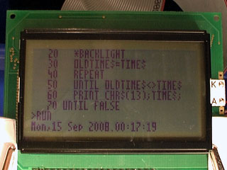
Finally, the obligatory video, this time showing a clock that toggles the backlight once a second.
Subscribe to an RSS feed that only contains items with the DS1307 tag.