Working out the Sharp CE-50P printer's character set
Sunday, 15th November 2026
I tend to have a way of getting sidetracked with hobby projects and as the scope increases, the chances of ever finishing steadily decreases. However, useful things can still be learned along the way, and sometimes they seem interesting enough to write about.
One of my current hobby projects is some software that can be used to transfer data to and from Sharp's graphing calculators. I was chiefly interested in the EL-9400, EL-9450, EL-9600, EL-9900 and EL-9950; these devices all seem to be broadly related to each other, and they are mostly compatible with each other as far as variable formats and data transfer protocols are concerned. I'd got the data transfer worked out, then decided to add variable editors to the software (so rather than just being able to transfer a binary blob of data back and forth, you could for example open a program and see its listing or edit the numeric data inside a list or matrix). I was due to start working on the equation editor (these calculators allow you to enter expressions using a graphical "textbook"-style editor) but couldn't really think of a good way to handle this so got sidetracked by the EL-9300.
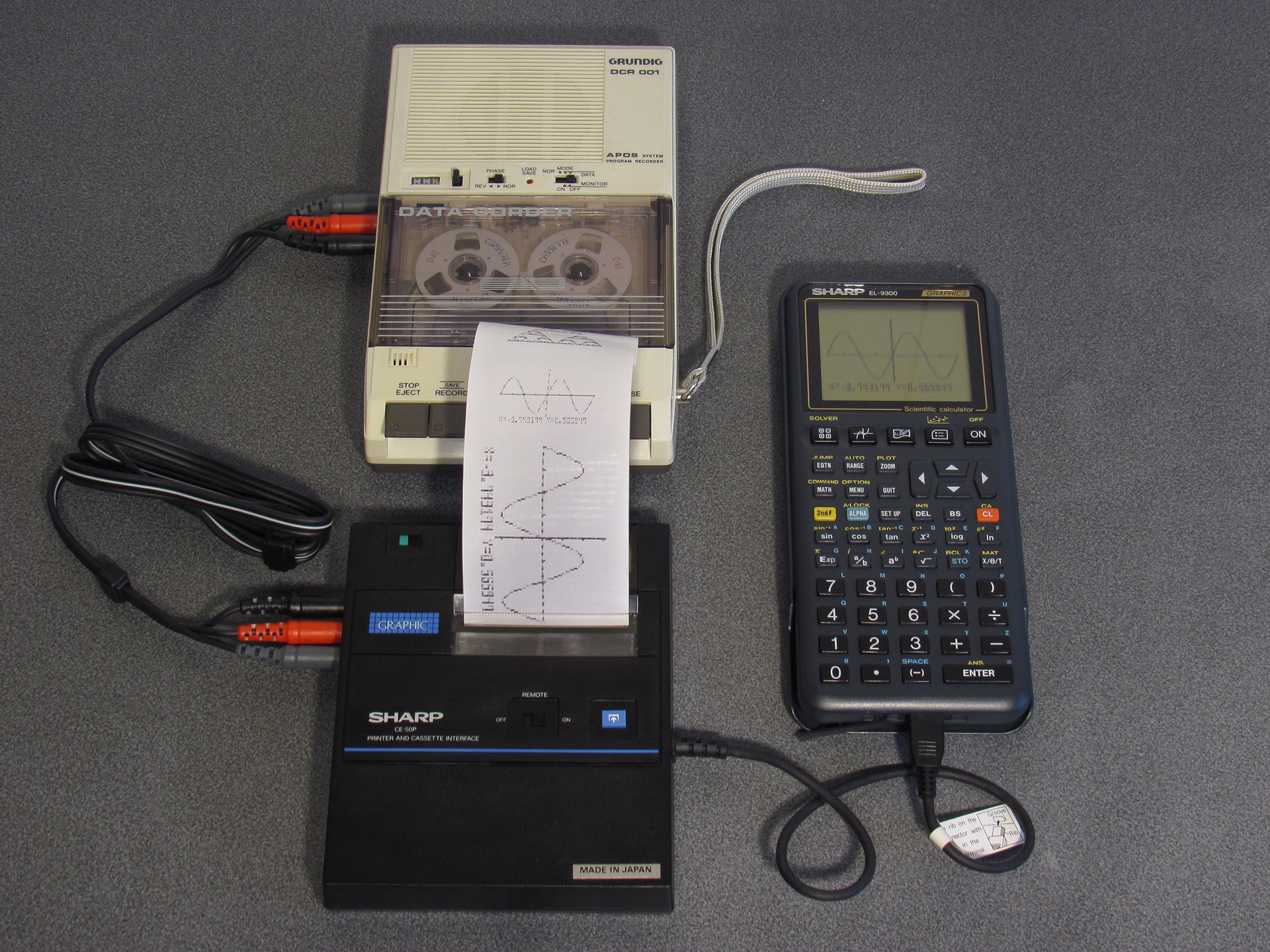
A Sharp EL-9300 connected to a CE-50P printer and cassette interface.
The EL-9300 is an older calculator model that shares a similar user interface to its younger siblings but it has some notable differences, one of which being its communication port. Rather than a 2.5mm TRS socket, it has a proprietary four-pin connector that could also be found on Sharp's organisers of the time. This allowed two calculators to be connected together, or for the calculator to be connected to a CE-50P printer and cassette interface for hard copies or long-term data storage on tape cassette. I don't know if accompanying PC transfer software was ever released by Sharp, but I do have a CE-136T "RS-232 level converter" that lets you connect devices with this four-pin port to a PC. By connecting a logic analyser to the CE-50P and sending various test prints or saving and loading from cassette from an organiser I'd been able to reverse-engineer the protcols and written some PC software that could emulate the CE-50P. This meant I could save to a "tape" on my PC and transfer data via a virtual tape image. This isn't ideal, as loading from tape replaces all other program records on the device, and the only way to transfer individual programs without clearing the others was directly from calculator to calculator. The answer, therefore, was to write some PC software that pretended to be an EL-9300 and could send and receive variable data, and then reverse-engineer those variable formats and write some editors similar to what I'd done for the later calculator models.
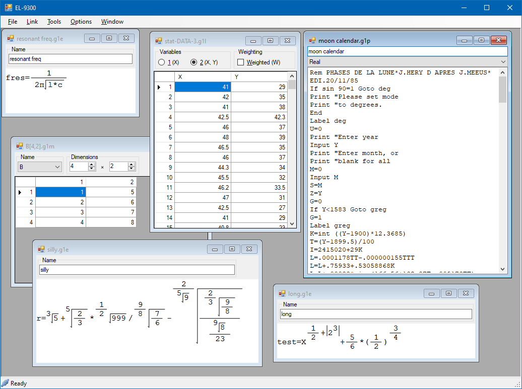
Work-in-progress PC link software for the Sharp EL-9300.
I worked on this software for a while, including starting work on the graphical equation editor. I'd got as far as being able to load and display (but not yet modify) solver equation variables copied from the EL-9300 before I got sidetracked again, this time by the EL-9000. This was Sharp's first graphing calculator, and the predecessor of the EL-9300. As far as I could tell it was quite different to use, but had the same four-pin communication port and also supported the CE-50P printer and cassette interface. I'd only been able to tell that by reading a scan of the manual, though, as this calculator seems to be somewhat rare and the only ones I'd seen for sale had been ferociously expensive, with sellers listing second-hand examples for several hundred pounds. I like vintage calculators but not quite as much as being able to afford to eat, so this seemed like it would remain out of reach until one popped up one day for around £30. Unfortunately, the reason for this comparatively low price seemed to be a black splodge of "LCD rot" in the middle of its display, so I thought I'd sleep on it. By the next morning it had sold, though, so that put an end to it... or so I thought. A few days later I got a notification that it had been re-listed at the old price, but by the time I got around to looking properly at the listing the price had halved, so I thought I'd be a fool to miss it again. I placed the order, and a few days later the calculator dropped through the letterbox.
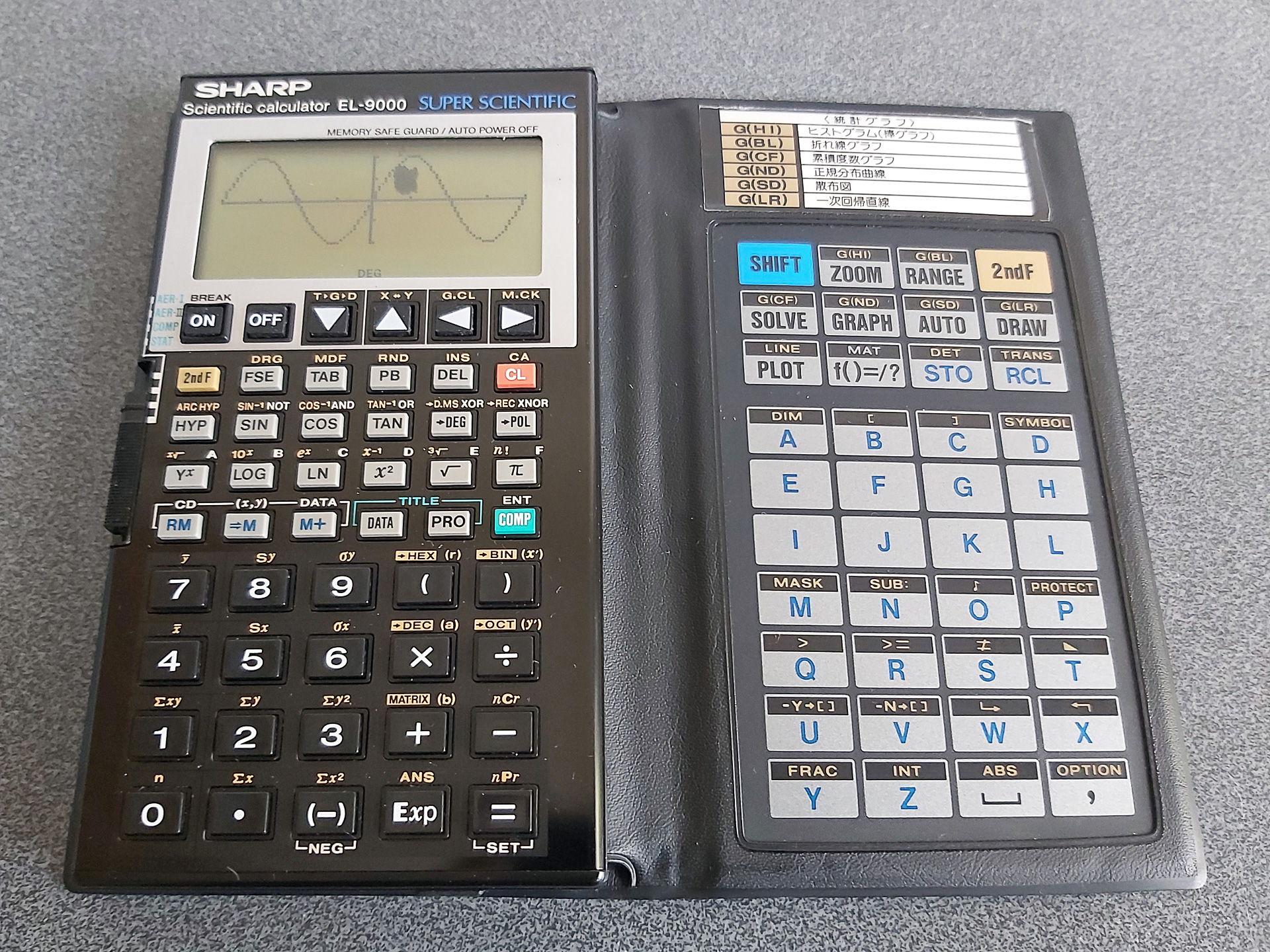
My Sharp EL-9000 with its damaged LCD. Fortunately all of the keys built into the folding cover work.
After playing with it for a while, I thought I'd try printing from it to my virtual CE-50P and almost immediately ran into issues. Every other Sharp organiser or calculator I'd tried before printed data by sending 0x59 followed by 128 bytes of pixel data, corresponding to an 8 pixel high line that filled the width of printable area. Most of these devices had 96 pixel wide displays, so they'd pad their 96 bytes of active screen data with 16 zeroes before and 16 zeroes after to reach the desired 128 bytes of data. The EL-9000 also has a 96 pixel wide display, however it printed data by sending 0x58 followed by 96 pixels of data – an option I wasn't aware existed before.
Things were even more surprising when I tried to print from the program editor, as instead of printing graphically as all of my other Sharp devices did the EL-9000 sent 0x51 followed by sixteen bytes of character data terminated by 0x0D, corresponding to the 16 columns of text on the screen. One thing that had previously puzzled me is that the CE-50P service manual describes a test mode (activated by holding the paper feed key whilst switching the printer on) which prints "an entire character set". I hadn't previously seen any devices attempt to print text directly like this, they always converted their text into a bitmap on the device and sent graphics data to the printer instead. The "entire character set" only runs as far as the lowercase 'h' in any case, so I thought maybe it was just an incomplete test pattern baked into the ROM, but no – it turns out there is a full character ROM inside the printer after all.
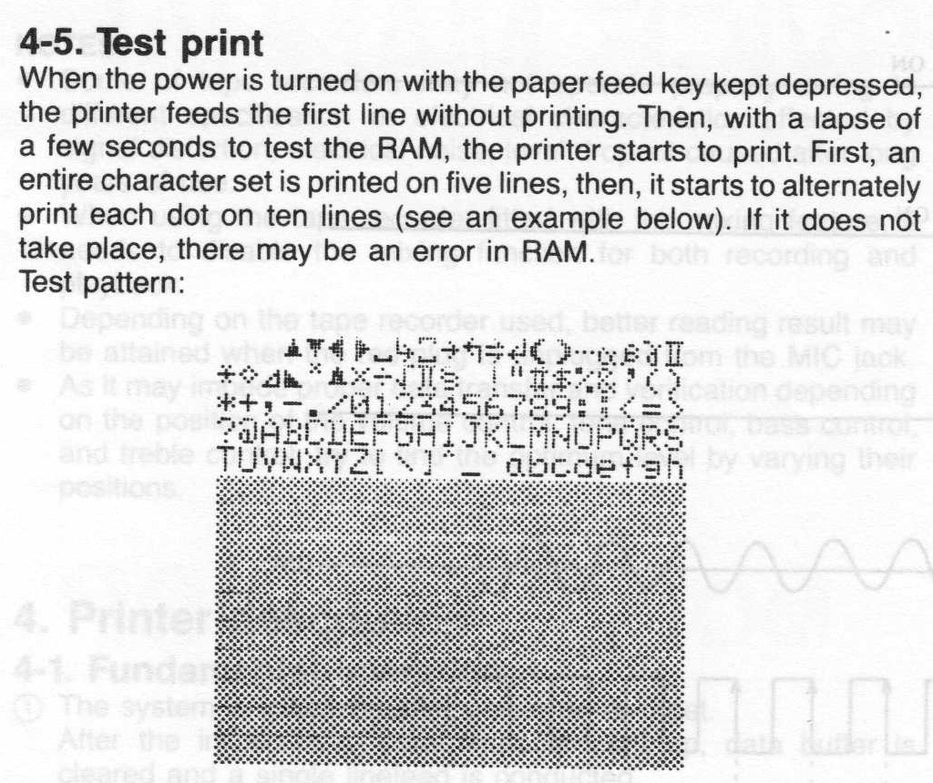
This posed a problem for my virtual CE-50P, though – how could I implement this feature without knowing what all of the characters looked like? As mentioned above I could at least use the test mode to identify the characters as far as 'h', but there are an awful lot more characters than that! By writing test programs on the EL-9000 that used as many of the available characters as I could, then printing them on a real CE-50P, I was able to fill in some of the gaps but there were still a lot of missing characters.
I do have a BASIC card for my Sharp organisers so I could try writing a program for those that would print every possible character, but the way that BASIC accesses the printer is graphical so I'd end up seeing the organiser's character set rather than the printer's, and I'd already established from the few non-ASCII characters I'd been able to identify that the two character sets did not match.
Fortunately the BASIC card lets you POKE data into memory then CALL it, so I should be able to write an assembly program that sent text to the printer. I'd still need to figure out how to do that, and working out how the organiser transferred bytes to the printer seemed like a good starting point. Fortunately I'd already hacked together Ghidra support for the organiser's ESR-L processor for a previous project where I was trying to figure out how I could enable 40-column text mode from the 16-column BASIC card, and so I started picking apart a dump of the IQ-7000 organiser's ROM using Ghidra as a disassembler.
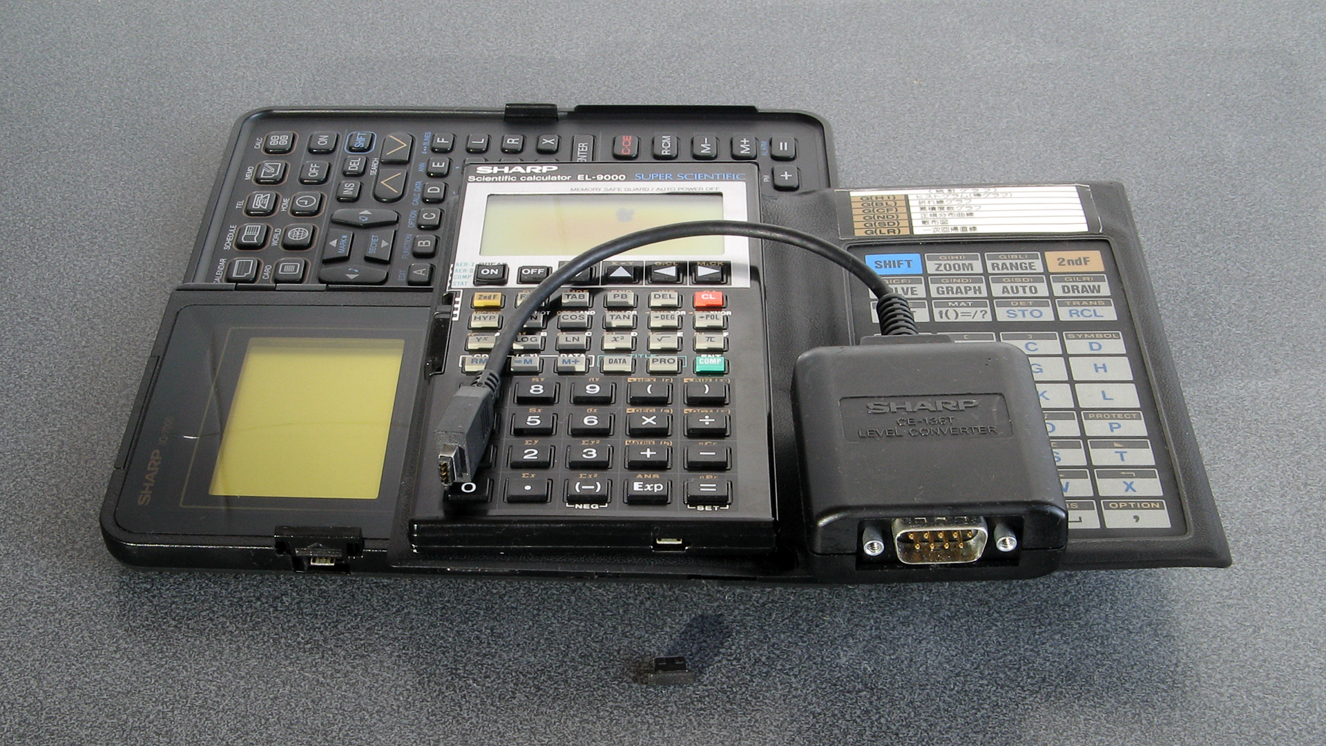
The Sharp CE-136T level converter, EL-9000 calculator and IQ-7000 organiser.
The 4-pin option port is below the screen of the organiser and below the Exp key of the calculator.
The first challenge was finding where in the ROM the code that dealt with the 4-pin option port was. According to the ESR-L Instruction Manual the CPU has a general I/O port called the "E-port" with sixteen I/O lines that could be accessed via four registers in its internal memory; EIL and EIH for input and EOL and EOH for output. Writing a program to run on the organiser that polled the input registers showed that bit 6 in register EIH (covering E8 to E15) changed state when I tried to send data to the organiser from my PC, so it looks like E14 is connected to one of the option port's I/O lines. Searching the ROM for bytes matching the EOH register found a cluster of code to disassemble that performed low-level port operations:
*************************************************************************
* Sets the So line.                                                     *
*************************************************************************
                    SET_SO
0fbbaf 30 79 f4 80       OR           (EOH),10000000b
0fbbb3 06                RET

*************************************************************************
* Resets the So line.                                                   *
*************************************************************************
                    RES_SO
0fbbb4 30 71 f4 7f       AND          (EOH),01111111b
0fbbb8 06                RET

*************************************************************************
* Gets state of Si line, returning the level in the carry flag.         *
*************************************************************************
                    GET_SI
0fbbb9 30 65 f6 40       TEST         (EIH),01000000b
0fbbbd 1a 02             JRNZ         GET_SI_HIGH
0fbbbf 9f                RC
0fbbc0 06                RET
                    GET_SI_HIGH
0fbbc1 97                SC
0fbbc2 06                RET

*************************************************************************
* Resets the So and Si lines.                                           *
*************************************************************************
                    RES_SOSI
0fbbc3 30 71 f4 3f       AND          (EOH),00111111b
0fbbc7 06                RET

*************************************************************************
* Sets the So and Si lines.                                             *
*************************************************************************
                    SET_SOSI
0fbbc8 30 79 f4 c0       OR           (EOH),11000000b
0fbbcc 06                RET
There are two data I/O lines on the 4-pin option port, referred to as "So" (source output, E15) and "Si" (sink output, E14). These are bidirectional (open collector) I/O lines and the code above uses "set" or "reset" (or "high" or "low") to denote the bit level (1 or 0) written to the port and not the actual voltage level, as at this point I just want to identify the code that is doing something with the option port. The above provides a good starting point. Now, it would seem likely that data that read bytes from the option port would call GET_SI to get the state of the Si line before rotating or shifting it into a byte variable. Now that I knew the address of the GET_SI routine (0x0fbbb9) I could search the ROM for that value to find out where it was being called from. More specifically, I'd need to truncate the address to sixteen bits as the routine returns with RET, which indicates it can only be called from the same segment; if it was intended to be called with the full 20-bit address it would need to return with RETF (the ESR-L can address up to 1MB of external memory, but this is divided into 16 segments of 64KB each).
A search was performed for the byte sequence 0xB9, 0xBB and sure enough, not far away there's a call to GET_SI followed by a left shift into the accumulator and a call to SET_SO which looks like the inner part of the byte-receiving routine:
0fbac1 04 b9 bb          CALL         GET_SI
0fbac4 f6                SHL          A
0fbac5 04 af bb          CALL         SET_SO
After some further disassembly above and below the identified code snippet, the full routine for getting a byte from the option port can be revealed:
*************************************************************************
* Gets a single byte                                                    *
*************************************************************************
                    OPTION_GET_BYTE
0fbaa2 0b eb 00          MV           I,235
0fbaa5 08 08             MV           A,8
0fbaa7 dd                EX           A,B
                    Wait for Si to go low.
                    WAIT_SI_LOW
0fbaa8 04 b9 bb          CALL         GET_SI
0fbaab 1e 0d             JRNC         SI_LOW
0fbaad 2b                PUSHU        I
0fbaae 04 cd bb          CALL         CHECK_BREAK
0fbab1 3b                POPU         I
0fbab2 1c 22             JRC          ERROR
0fbab4 7c 03             DEC          I
0fbab6 1b 10             JRNZ         WAIT_SI_LOW
0fbab8 12 1a             JR           ERROR_0
                    Si has gone low, so set So low.
                    SI_LOW
0fbaba 04 b4 bb          CALL         RES_SO
                    Sampling delay
0fbabd 0b e5 00          MV           I,229
0fbac0 ef                WAIT
                    Clock in data from Si.
0fbac1 04 b9 bb          CALL         GET_SI
0fbac4 f6                SHL          A
                    Set So high.
0fbac5 04 af bb          CALL         SET_SO
                    Wait for Si to go high
0fbac8 0b 9e 04          MV           I,1182
                    WAIT_SI_HIGH
0fbacb 04 b9 bb          CALL         GET_SI
0fbace 1c 0b             JRC          SI_HIGH
0fbad0 7c 03             DEC          I
0fbad2 1b 09             JRNZ         WAIT_SI_HIGH
                    ERROR_0
0fbad4 08 00             MV           A,0
                    ERROR
0fbad6 04 c3 bb          CALL         RES_SOSI
0fbad9 97                SC
0fbada 06                RET
                    Check if we've received all the bits
                    SI_HIGH
0fbadb dd                EX           A,B
0fbadc 7c 00             DEC          A
0fbade dd                EX           A,B
0fbadf 1b 39             JRNZ         WAIT_SI_LOW
                    Short delay loop
0fbae1 09 13             MV           IL,19
                    DELAY
0fbae3 7c 01             DEC          IL
0fbae5 1b 04             JRNZ         DELAY
                    Clear carry to denote success, then return
0fbae7 9f                RC
0fbae8 06                RET
This routine has all of the expected features of a byte-receiving routine; this includes delay loops, a counter for the eight bits of data to shift in, and counters to detect timeout (if a pin doesn't change to the expect state within a certain number of times around a loop, jump to the label that sets the error condition then bail out). It also calls a routine that I called CHECK_BREAK that checks some other bits of the organiser's state and returns error codes like "low battery" so I assume is part of the logic used to break out of communication routines in emergencies (either the aforementioned low battery state or if the On key is pressed – I haven't disassembled much of the code that the CHECK_BREAK routine also calls, so this is mostly a hunch). Immediately after the OPTION_GET_BYTE routine is this one:
*************************************************************************
* Gets a single byte, updates the checksum                              *
*************************************************************************
                    OPTION_GET_BYTE_CHECKSUM
0fbae9 04 a2 ba          CALL         OPTION_GET_BYTE
0fbaec 1c 08             JRC          EXIT
0fbaee 30 43 d8          ADD          (DL),A
0fbaf1 30 51 d9 00       ADC          (DH),0
0fbaf5 9f                RC
                    EXIT
0fbaf6 06                RET
After receiving a byte successfully via OPTION_GET_BYTE it adds the received value to the sixteen-bit DX variable, so this very much looks like part of the code that handles updating a checksum as data is received. The next routine is similar, but calls a variation of the GET_BYTE routine that I called OPTION_GET_BYTE_WAIT_INFINITE as instead of bailing out if it can't receive a byte within a short timeout period it will loop infinitely trying to receive a byte (though it does still bail out if CHECK_BREAK reports an error/break condition). The next GET_BYTE variation waits for up to a full minute before timing out:
*************************************************************************
* Gets a single byte.                                                   *
* Waits for up to one minute for the byte.                              *
*************************************************************************
                    OPTION_GET_BYTE_WAIT_MINUTE
0fbb05 08 08             MV           A,8
0fbb07 dd                EX           A,B
0fbb08 0b e0 2e          MV           I,12000
                    WAIT_SI_LOW
0fbb0b 04 b9 bb          CALL         GET_SI
0fbb0e 1f 56             JRNC         OPTION_GET_BYTE::SI_LOW
0fbb10 04 48 ad          CALL         DELAY_5MS
0fbb13 2b                PUSHU        I
0fbb14 04 cd bb          CALL         CHECK_BREAK
0fbb17 3b                POPU         I
0fbb18 1d 44             JRC          OPTION_GET_BYTE::ERROR
0fbb1a 7c 03             DEC          I
0fbb1c 1b 13             JRNZ         WAIT_SI_LOW
0fbb1e 13 4c             JR           OPTION_GET_BYTE::ERROR_0
This tries to receive a byte 12000 times before bailing out, and calls a routine that delays for 5ms, hence the one minute total timeout. This covers quite a few routines that receive bytes, surely we'd need some routines to send bytes too? Searching for routines that referenced the addresses of the RES_SO and SET_SO routines soon found the basic OPTION_SEND_BYTE routine:
*************************************************************************
* Sends a single byte.                                                  *
*************************************************************************
                    OPTION_SEND_BYTE
0fbb2f dd                EX           A,B
0fbb30 08 08             MV           A,8
0fbb32 dd                EX           A,B
                    SEND_BIT
0fbb33 0b eb 00          MV           I,235
0fbb36 04 b4 bb          CALL         RES_SO
                    WAIT_SI_LOW
0fbb39 04 b9 bb          CALL         GET_SI
0fbb3c 1e 12             JRNC         SI_LOW
0fbb3e 2b                PUSHU        I
0fbb3f 04 cd bb          CALL         CHECK_BREAK
0fbb42 3b                POPU         I
0fbb43 1c 06             JRC          ERROR
0fbb45 7c 03             DEC          I
0fbb47 1b 10             JRNZ         WAIT_SI_LOW
                    ERROR_0
0fbb49 08 00             MV           A,0
                    ERROR
0fbb4b 04 c3 bb          CALL         RES_SOSI
0fbb4e 97                SC
0fbb4f 06                RET
                    SI_LOW
0fbb50 e6                ROL          A
0fbb51 1c 05             JRC          SO_HIGH
0fbb53 04 b4 bb          CALL         RES_SO
0fbb56 12 03             JR           SO_CHANGED
                    SO_HIGH
0fbb58 04 af bb          CALL         SET_SO
                    SO_CHANGED
0fbb5b 0b 9e 04          MV           I,1182
                    WAIT_SI_HIGH
0fbb5e 04 b9 bb          CALL         GET_SI
0fbb61 1c 06             JRC          SI_HIGH
0fbb63 7c 03             DEC          I
0fbb65 1b 09             JRNZ         WAIT_SI_HIGH
0fbb67 13 20             JR           ERROR_0
                    SI_HIGH
0fbb69 04 af bb          CALL         SET_SO
0fbb6c 09 1e             MV           IL,30
                    DELAY_30_LOOP
0fbb6e 7c 01             DEC          IL
0fbb70 1b 04             JRNZ         DELAY_30_LOOP
0fbb72 dd                EX           A,B
0fbb73 7c 00             DEC          A
0fbb75 18 03             JRZ          SUCCESS
0fbb77 dd                EX           A,B
0fbb78 13 47             JR           SEND_BIT
                    SUCCESS
0fbb7a 9f                RC
0fbb7b 06                RET
This has a lot of similarity to the OPTION_GET_BYTE routine, except instead of calling GET_SI and shifting the received bit into the accumulator, it rotates the accumulator to find the bit to send then calls RES_SO or SET_SO to output the appropriate voltage level for that bit. Immediately after this routine is a variation that calls DELAY_5MS twice to introduce a 10ms delay between bytes:
*************************************************************************
* Waits 10ms, then sends a single byte.                                 *
*************************************************************************
                    OPTION_DELAYED_SEND_BYTE
0fbb7c 04 48 ad          CALL         DELAY_5MS
0fbb7f 04 48 ad          CALL         DELAY_5MS
0fbb82 04 2f bb          CALL         OPTION_SEND_BYTE
0fbb85 06                RET
...before the version of the routine that updates the checksum held in DX before transmitting the byte:
*************************************************************************
* Updates the checksum, then sends a single byte.                       *
*************************************************************************
                    OPTION_SEND_BYTE_CHECKSUM
0fbb86 30 43 d8          ADD          (DL),A
0fbb89 30 51 d9 00       ADC          (DH),0
0fbb8d 04 2f bb          CALL         OPTION_SEND_BYTE
0fbb90 06                RET
There are also routines that attempt to send the byte with an infinite timeout, with or without updating the checksum, similar to the variations available for receiving bytes.
Having these basic routines to send and receive bytes via the option port is useful, but seeing how they can be used together to actually control the printer is the real goal. Fortunately I had already figured out what a lot of the printer control command bytes are by using a logic analyser to observe what data is sent when an organiser prints something, so that gave me some command bytes to look for, e.g.:
- 0xC0: Initialise printer
- 0x59: Print a line of graphics data (128 bytes of data follows this)
- 0x70: End a print operation
- 0xAA: Get a device's ID (the printer will respond with 0x01, 0xF0)
Using the same technique as before – searching the memory for addresses of the individual byte-transfer routines to see where they are being called and disassembling the surrounding code – revealed a series of routines next to each other that perform printer-related operations, matching the command codes mentioned above:
*************************************************************************
* Initialise the printer                                                *
*************************************************************************
                    PRINTER_INIT
0fb828 04 67 b8          CALL         PRINTER_ID_CHECK
0fb82b 1c 0d             JRC          ERROR
0fb82d 08 c0             MV           A,0xc0
0fb82f 04 7c bb          CALL         OPTION_DELAYED_SEND_BYTE
0fb832 1c 06             JRC          ERROR
0fb834 04 67 ad          CALL         DELAY_1MS
0fb837 04 9a b9          CALL         OPTION_GET_ACK
                    ERROR
0fb83a 2e                PUSHU        F
0fb83b 04 c3 bb          CALL         RES_SOSI
0fb83e 04 48 ad          CALL         DELAY_5MS
0fb841 3e                POPU         F
0fb842 06                RET

*************************************************************************
* Begin printing a line                                                 *
*************************************************************************
                    PRINTER_BEGIN_LINE
0fb843 08 59             MV           A,0x59
0fb845 04 7c bb          CALL         OPTION_DELAYED_SEND_BYTE
0fb848 1c 04             JRC          ERROR
0fb84a 04 67 b9          CALL         OPTION_SEND_ZEROES
0fb84d 06                RET
                    ERROR
0fb84e 97                SC
0fb84f 06                RET

*************************************************************************
* End a print                                                           *
*************************************************************************
                    PRINTER_END_PRINT
0fb850 04 67 ad          CALL         DELAY_1MS
0fb853 08 70             MV           A,0x70
0fb855 04 2f bb          CALL         OPTION_SEND_BYTE
0fb858 1c 0c             JRC          EXIT
0fb85a 04 67 ad          CALL         DELAY_1MS
0fb85d 04 9a b9          CALL         OPTION_GET_ACK
0fb860 1c 04             JRC          EXIT
0fb862 04 c3 bb          CALL         RES_SOSI
0fb865 9f                RC
                    EXIT
0fb866 06                RET

*************************************************************************
* Check if a printer is attached.                                       *
*************************************************************************
                    PRINTER_ID_CHECK
0fb867 04 15 ba          CALL         OPTION_ID_DEVICE_AA
0fb86a 1c 0d             JRC          ERROR
0fb86c 60 01             CMP          A,0x1
0fb86e 1a 07             JRNZ         ERROR_0
0fb870 dd                EX           A,B
0fb871 60 f0             CMP          A,0xf0
0fb873 1a 02             JRNZ         ERROR_0
0fb875 9f                RC
0fb876 06                RET
                    ERROR_0
0fb877 08 00             MV           A,0
                    ERROR
0fb879 97                SC
0fb87a 06                RET
Immediately before these is a slightly longer routine that uses them to either print a single 8-pixel-high row of data from the screen (if register A is from 0 to 7) or from 96 bytes of graphics data pointed to by the X register (if A is -1). Note that OPTION_SEND_ZEROES in this routine and in PRINTER_BEGIN_LINE sends 16 zero bytes to pad the 96 bytes of actual printer data with blank space on either side to make up the full 128 byte printer width.
*************************************************************************
* Print a line of data on the printer.                                  *
* If A = -1, X is a pointer to bitmap data.                             *
* If A is not -1, it's the row on the screen to print.                  *
*************************************************************************
                    PRINTER_PRINT_GRAPHICS_LINE
0fb7c5 60 ff             CMP          A,0xff
0fb7c7 18 42             JRZ          X_IS_POINTER
0fb7c9 4d 55             SUB          Y,Y
                    A is not -1, so use it as the line number
                    FIND_Y
0fb7cb 60 00             CMP          A,0
0fb7cd 18 08             JRZ          GOT_Y
0fb7cf 09 08             MV           IL,8
0fb7d1 45 51             ADD          Y,IL
0fb7d3 7c 00             DEC          A
0fb7d5 13 0c             JR           FIND_Y
                    GOT_Y
0fb7d7 04 43 b8          CALL         PRINTER_BEGIN_LINE
0fb7da 1c 47             JRC          ERROR
0fb7dc 4d 44             SUB          X,X
                    A_IS_LINE_NUMBER_LOOP
0fb7de 2c                PUSHU        X
0fb7df 2d                PUSHU        Y
0fb7e0 30 cd d6 00       MVW          (CX),0
       00
0fb7e5 09 4b             MV           IL,0x4b
0fb7e7 05 e8 ff 0f       CALLF        IOCS
0fb7eb 3d                POPU         Y
0fb7ec 3c                POPU         X
0fb7ed 04 2f bb          CALL         OPTION_SEND_BYTE
0fb7f0 1c 31             JRC          ERROR
0fb7f2 6c 04             INC          X
0fb7f4 30 a4 da          MV           (SI),X
0fb7f7 30 61 da 60       CMP          (SI),96
0fb7fb 1b 1f             JRNZ         A_IS_LINE_NUMBER_LOOP
                    PAD_LINE_END
0fb7fd 04 67 b9          CALL         OPTION_SEND_ZEROES
0fb800 1c 21             JRC          ERROR
0fb802 04 67 ad          CALL         DELAY_1MS
0fb805 04 9a b9          CALL         OPTION_GET_ACK
0fb808 1c 5c             JRC          PRINTER_END_PRINT::EXIT
0fb80a 06                RET
                    X_IS_POINTER
0fb80b 04 43 b8          CALL         PRINTER_BEGIN_LINE
0fb80e 1c 13             JRC          ERROR
0fb810 0d 60 00 00       MV           Y,96
                    X_IS_POINTER_LOOP
0fb814 90 24             MV           A,[X++]
0fb816 04 2f bb          CALL         OPTION_SEND_BYTE
0fb819 1c 08             JRC          ERROR
0fb81b 7c 05             DEC          Y
0fb81d 1b 0b             JRNZ         X_IS_POINTER_LOOP
0fb81f 13 24             JR           PAD_LINE_END
                    ERROR_0
0fb821 08 00             MV           A,0x0
                    ERROR
0fb823 04 c3 bb          CALL         RES_SOSI
0fb826 97                SC
0fb827 06                RET
This routine is then used as a building block in a more comprehensive routine, that also allows the user to pass -2 in register A to print the whole screen. This version of the routine also initialises the printer and preserves some state on entry and restores it on exit via OPTION_PRESERVE and OPTION_RESTORE routines:
*************************************************************************
* Prints either a line of graphics data or the whole screen.            *
* If A = -2, the whole screen is printed.                               *
* If A = -1, X is a pointer to bitmap data for a single line.           *
* If A is 0 to 7, it's the row on the screen to print.                  *
*************************************************************************
                    PRINTER_PRINT_GRAPHICS_LINE_OR_SCREEN
0fb6fd 04 eb bb          CALL         OPTION_PRESERVE
0fb700 60 fe             CMP          A,0xfe
0fb702 18 1b             JRZ          FULL_SCREEN
0fb704 28                PUSHU        A
0fb705 04 67 b8          CALL         PRINTER_ID_CHECK
0fb708 1c 0f             JRC          POP_EXIT
0fb70a 38                POPU         A
0fb70b 04 c5 b7          CALL         PRINTER_PRINT_GRAPHICS_LINE
0fb70e 1c 0a             JRC          EXIT
0fb710 04 50 b8          CALL         PRINTER_END_PRINT
0fb713 1c 05             JRC          EXIT
0fb715 04 e0 bb          CALL         OPTION_RESTORE
0fb718 06                RET
                    POP_EXIT
0fb719 39                POPU         IL
                    EXIT
0fb71a 04 e0 bb          CALL         OPTION_RESTORE
0fb71d 97                SC
0fb71e 06                RET
                    FULL_SCREEN
0fb71f 30 7d ec          DEC          (BP)
0fb722 04 60 09          CALL         FUN_0f0960
0fb725 88 a1 fd 01       MV           A,[TEXTFLAGS]
0fb729 28                PUSHU        A
0fb72a 72 a1 fd 01       AND          [TEXTFLAGS],0xdf
       df
0fb72f 7a a1 fd 01       OR           [TEXTFLAGS],0x40
       40
0fb734 30 cd d6 00       MVW          (CX),0x0
       00
0fb739 09 5e             MV           IL,0x5e
0fb73b 4d 44             SUB          X,X
0fb73d 30 cd d4 00       MVW          (BX),0x700
       07
0fb742 30 cd d8 0f       MVW          (DL),0x70f
       07
0fb747 05 e8 ff 0f       CALLF        IOCS
0fb74b 30 cd d4 00       MVW          (BX),0x700
       07
0fb750 0c b5 b7 0f       MV           X,PRINTING_CAPTION = "   -PRINTING-   "
0fb754 0d 10 00 00       MV           Y,0x10
0fb758 4c 22             SUB          BA,BA
0fb75a 30 cd d6 00       MVW          (CX),0x0
       00
0fb75f 09 42             MV           IL,0x42
0fb761 05 e8 ff 0f       CALLF        IOCS
0fb765 04 28 b8          CALL         PRINTER_INIT
0fb768 1c 29             JRC          FULL_SCREEN_EXIT
0fb76a 04 67 b8          CALL         PRINTER_ID_CHECK
0fb76d 1c 24             JRC          FULL_SCREEN_EXIT
0fb76f cc 00 00          MV           (BP+0x0),0x0
                    FULL_SCREEN_LOOP
0fb772 80 00             MV           A,(BP+0x0)
0fb774 04 c5 b7          CALL         PRINTER_PRINT_GRAPHICS_LINE
0fb777 1c 1a             JRC          FULL_SCREEN_EXIT
0fb779 6d 00             INC          (BP+0x0)
0fb77b 61 00 07          CMP          (BP+0x0),7
0fb77e 1b 0e             JRNZ         FULL_SCREEN_LOOP
0fb780 fd 46             MV           X,U
0fb782 08 06             MV           A,6
0fb784 45 40             ADD          X,A
0fb786 08 ff             MV           A,0xff
0fb788 04 c5 b7          CALL         PRINTER_PRINT_GRAPHICS_LINE
0fb78b 1c 06             JRC          FULL_SCREEN_EXIT
0fb78d 04 50 b8          CALL         PRINTER_END_PRINT
0fb790 1c 01             JRC          FULL_SCREEN_EXIT
0fb792 9f                RC
                    FULL_SCREEN_EXIT
0fb793 b0 37             MV           [--S],A
0fb795 4f                PUSHS        F
0fb796 30 6d ec          INC          (BP)
0fb799 30 cd d6 00       MVW          (CX),0
       00
0fb79e 09 5f             MV           IL,0x5f
0fb7a0 4d 44             SUB          X,X
0fb7a2 05 e8 ff 0f       CALLF        IOCS
0fb7a6 38                POPU         A
0fb7a7 a8 a1 fd 01       MV           [TEXTFLAGS],A
0fb7ab 04 97 09          CALL         FUN_0f0997
0fb7ae 5f                POPS         F
0fb7af 90 27             MV           A,[S++]
0fb7b1 04 e0 bb          CALL         OPTION_RESTORE
0fb7b4 06                RET
                    PRINTING_CAPTION
0fb7b5 20 20 20 2d       char[16]     "   -PRINTING-   "
       50 52 49 4e
       54 49 4e 47
Knowing that these routines exist and where to find them in the ROM is one thing, but how were they intended to be called? I also have a ROM dump from an IQ-7400 organiser and the routines aren't at the same memory addresses, and most of them return with RET which means they can only be called from the same segment. The PC-E500's technical reference manual describes a routine called IOCS that performs certain operations on I/O devices based on a device and drive number in variable CX and a command number in register I, so it would seem likely that somewhere in the ROM is a table of addresses that map the command numbers to their respective routines.
Searching for some of the addresses of routines that were likely to be made publicly accessible soon produced a table of routines that could be called along with the routine that would invoke the target routine with the command number in the register IL:
*************************************************************************
* Calls a printer routine with the command number in IL.                *
*************************************************************************
                    PRINTER_FN
0fb477 2a                PUSHU        BA
0fb478 2c                PUSHU        X
0fb479 fd 01             MV           A,IL
0fb47b 60 3f             CMP          A,0x3f
0fb47d 1e 11             JRNC         FN_3F_OR_OVER
0fb47f 48 08             SUB          A,0x8
0fb481 0c 98 b4 0f       MV           X,FN_TABLE
                    INVOKE
0fb485 45 40             ADD          X,A
0fb487 45 40             ADD          X,A
0fb489 92 04             MV           BA,[X]
0fb48b b2 37             MV           [--S],BA
0fb48d 3c                POPU         X
0fb48e 3a                POPU         BA
0fb48f 06                RET
                    FN_3F_OR_OVER
0fb490 0c a6 b4 0f       MV           X,FN_TABLE_3F_OR_OVER
0fb494 48 3f             SUB          A,0x3f
0fb496 13 13             JR           INVOKE
                    FN_TABLE
0fb498 dc b5             ushort       B5DCh      0x08 ? PRINTER_IOCS_08
0fb49a 00 b6             ushort       B600h      0x09 ? PRINTER_IOCS_09
0fb49c e6 b4             ushort       B4E6h      0x0A PRINTER_DRIVE_DOES_NOT_EXIST
0fb49e fc b4             ushort       B4FCh      0x0B ? PRINTER_IOCS_0B
0fb4a0 e6 b4             ushort       B4E6h      0x0C PRINTER_DRIVE_DOES_NOT_EXIST
0fb4a2 05 b6             ushort       B605h      0x0D ? PRINTER_IOCS_0D
0fb4a4 e6 b4             ushort       B4E6h      0x0E PRINTER_DRIVE_DOES_NOT_EXIST
                    FN_TABLE_3F_OR_OVER
0fb4a6 ed b9             ushort       B9EDh      0x3F PRINTER_RESET
0fb4a8 ea b4             ushort       B4EAh      0x40 PRINTER_RESET_A
0fb4aa fd b6             ushort       B6FDh      0x41 PRINTER_PRINT_GRAPHICS_LINE_OR_SCREEN
0fb4ac 5d b9             ushort       B95Dh      0x42 PRINTER_PRINT_TEXT_0_SAFE
0fb4ae 53 b9             ushort       B953h      0x43 PRINTER_PRINT_TEXT_1_SAFE
0fb4b0 dc b5             ushort       B5DCh      0x44 ? PRINTER_IOCS_08
0fb4b2 00 b6             ushort       B600h      0x45 ? PRINTER_IOCS_09
0fb4b4 05 b6             ushort       B605h      0x46 ? PRINTER_IOCS_0D
0fb4b6 fc b4             ushort       B4FCh      0x47 ? PRINTER_IOCS_OB
0fb4b8 c3 bb             ushort       BBC3h      0x48 RES_SOSI
0fb4ba af bb             ushort       BBAFh      0x49 SET_SO
0fb4bc b4 bb             ushort       BBB4h      0x4A RES_SO
0fb4be b9 bb             ushort       BBB9h      0x4B GET_SI
0fb4c0 28 b8             ushort       B828h      0x4C PRINTER_INIT
0fb4c2 15 ba             ushort       BA15h      0x4D OPTION_ID_DEVICE_AA
0fb4c4 38 ba             ushort       BA38h      0x4E OPTION_ID_DEVICE_A5
0fb4c6 63 ba             ushort       BA63h      0x4F SET_SO_CHECK_SI_HIGH_ERR_RES_SO
0fb4c8 81 ba             ushort       BA81h      0x50 SET_SO_CHECK_SI_HIGH
0fb4ca 9a b9             ushort       B99Ah      0x51 OPTION_GET_ACK
0fb4cc 7c bb             ushort       BB7Ch      0x52 OPTION_DELAYED_SEND_BYTE
0fb4ce 2f bb             ushort       BB2Fh      0x53 OPTION_SEND_BYTE
0fb4d0 86 bb             ushort       BB86h      0x54 OPTION_SEND_BYTE_CHECKSUM
0fb4d2 91 bb             ushort       BB91h      0x55 OPTION_SEND_BYTE_CHECKSUM_WAIT_IN
0fb4d4 9c bb             ushort       BB9Ch      0x56 OPTION_SEND_BYTE_WAIT_INFINITE
0fb4d6 a2 ba             ushort       BAA2h      0x57 OPTION_GET_BYTE
0fb4d8 e9 ba             ushort       BAE9h      0x58 OPTION_GET_BYTE_CHECKSUM
0fb4da f7 ba             ushort       BAF7h      0x59 OPTION_GET_BYTE_CHECKSUM_WAIT_INF
0fb4dc 05 bb             ushort       BB05h      0x5A OPTION_GET_BYTE_WAIT_MINUTE
0fb4de 20 bb             ushort       BB20h      Ox5B OPTION_GET_BYTE_WAIT_INFINITE
0fb4e0 cd bb             ushort       BBCDh      0x5C CHECK_BREAK
0fb4e2 eb bb             ushort       BBEBh      0x5D OPTION_PRESERVE
0fb4e4 e0 bb             ushort       BBE0h      0x5E OPTION_RESTORE

*************************************************************************
* Sets carry flag and error code A to 0x01,                             *
* "The drive does not exist".                                           *
*************************************************************************
                    PRINTER_DRIVE_DOES_NOT_EXIST
0fb4e6 08 01             MV           A,0x1
0fb4e8 97                SC
0fb4e9 06                RET
As it seems likely that this is part of the organiser's IOCS routine, the problem can now be approached from the opposite direction – look for code that handles the call to IOCS and find where it calls the printer PRINTER_FN routine that was just identifie. In fact, we don't even need to go that far, as each device that can be accessed via IOCS (screen, keyboard, serial port, option port etc) has a "header" that describes it, including its device name and entry point of its routine handler, so finding this table of headers should be enough. Searching the ROM for the printer device name "PRN:" soon finds it, fourth in the list of devices:
                    IOCS_HDR_STDO_SCRN
0f03f5 08 04 0f          addr         IOCS_HDR_STDI_KYBD
0f03f8 00                db           0h
0f03f9 a2                db           A2h
0f03fa a5 04 0f          addr         LAB_0f04a5
0f03fd 53 54 44 4f       ds           "STDO:SCRN:"
       3a 53 43 52
       4e 3a 00
                    IOCS_HDR_STDI_KYBD
0f0408 1b 04 0f          addr         IOCS_HDR_COM
0f040b 01                db           1h
0f040c a1                db           A1h
0f040d 0a 36 0f          addr         LAB_0f360a
0f0410 53 54 44 49       ds           "STDI:KYBD:"
       3a 4b 59 42
       44 3a 00
                    IOCS_HDR_COM
0f041b 28 04 0f          addr         IOCS_HDR_STDL_PRN
0f041e 02                db           2h
0f041f d3                db           D3h
0f0420 fe a5 0f          addr         FUN_0fa5fe
0f0423 43 4f 4d 3a       ds           "COM:"
       00
                    IOCS_HDR_STDL_PRN
0f0428 3a 04 0f          addr         IOCS_HDR_CAS
0f042b 03                db           3h
0f042c a2                db           A2h
0f042d 39 b4 0f          addr         PRINTER_FN_PRESERVE
0f0430 53 54 44 4c       ds           "STDL:PRN:"
       3a 50 52 4e
       3a 00
                    IOCS_HDR_CAS
0f043a 47 04 0f          addr         IOCS_HDR_S1_S2_S3
0f043d 04                db           4h
0f043e d7                db           D7h
0f043f c0 ae 0f          addr         FUN_0faec0
0f0442 43 41 53 3a       ds           "CAS:"
       00
                    IOCS_HDR_S1_S2_S3
0f0447 59 04 0f          addr         IOCS_HDR_SYSTM
0f044a 06                db           6h
0f044b c3                db           C3h
0f044c 83 7c 0f          addr         LAB_0f7c83
0f044f 53 31 3a 53       ds           "S1:S2:S3:"
       32 3a 53 33
       3a 00
                    IOCS_HDR_SYSTM
0f0459 68 04 0f          addr         IOCS_HDR_RTC
0f045c 08                db           8h
0f045d 00                db           0h
0f045e 02 57 0f          addr         LAB_0f5702
0f0461 53 59 53 54       ds           "SYSTM:"
       4d 3a 00
                    IOCS_HDR_RTC
0f0468 75 04 0f          addr         IOCS_HDR_PANET
0f046b 0a                db           Ah
0f046c 00                db           0h
0f046d ef 31 0f          addr         LAB_0f31ef
0f0470 52 54 43 3a       ds           "RTC:"
       00
                    IOCS_HDR_PANET
0f0475 84 04 0f          addr         IOCS_HDR_PACOM
0f0478 0b                db           Bh
0f0479 c0                db           C0h
0f047a 3d bc 0f          addr         LAB_0fbc3d
0f047d 50 41 4e 45       ds           "PANET:"
       54 3a 00
                    IOCS_HDR_PACOM
0f0484 93 04 0f          addr         IOCS_HDR_UNKNOWN_1
0f0487 0c                db           Ch
0f0488 53                db           53h
0f0489 00 bc 0f          addr         LAB_0fbc00
0f048c 50 41 43 4f       ds           "PACOM:"
       4d 3a 00
                    IOCS_HDR_UNKNOWN_1
0f0493 9c 04 0f          addr         IOCS_HDR_UNKNOWN_2
0f0496 0d                db           Dh
0f0497 00                db           0h
0f0498 77 67 0f          addr         LAB_0f6777
0f049b 00                ds           ""
                    IOCS_HDR_UNKNOWN_2
0f049c ff ff 0f          addr         LAB_0fffff
0f049f 0e                db           Eh
0f04a0 00                db           0h
0f04a1 88 5c 0f          addr         LAB_0f5c88
0f04a4 00                ds           ""
From this we can see that the printer has device number 0x03, attributes 0xA2 (bit 7: "able to handle file-control", bit 5: "character device", bit 1: "write enable") and a handler at 0x0fb439 which I named PRINTER_FN_PRESERVE as it looks like this:
                    PRINTER_FN_PRESERVE
0fb439 04 43 b4          CALL         PRINTER_STATE_PRESERVE
0fb43c 04 77 b4          CALL         PRINTER_FN
0fb43f 04 5d b4          CALL         PRINTER_STATE_RESTORE
0fb442 07                RETF

                    PRINTER_STATE_PRESERVE
0fb443 30 ea 36 da       MVP          [--U],(SI)
0fb447 30 ea 36 dd       MVP          [--U],(DAT_0000dd)
0fb44b 30 e9 36 d4       MVW          [--U],(BX)
0fb44f 30 e9 36 d6       MVW          [--U],(CX)
0fb453 30 e9 36 d8       MVW          [--U],(DL)
0fb457 30 e8 36 ed       MV           [--U],(PX)
0fb45b 2b                PUSHU        I
0fb45c 06                RET

                    PRINTER_STATE_RESTORE
0fb45d 3b                POPU         I
0fb45e 30 e0 26 ed       MV           (PX),[U++]
0fb462 30 e1 26 d8       MVW          (DL),[U++]
0fb466 30 e1 26 d6       MVW          (CX),[U++]
0fb46a 30 e1 26 d4       MVW          (BX),[U++]
0fb46e 30 e2 26 dd       MVP          (DAT_0000dd),[U++]
0fb472 30 e2 26 da       MVP          (SI),[U++]
0fb476 06                RET
That is, a bunch of variables and the I register are preserved on the user stack before PRINTER_FN is called and then restored afterwards. Knowing all this we can finally try to print something from assembly! Previously we'd looked at the PRINTER_PRINT_GRAPHICS_LINE_OR_SCREEN routine, which we know will print the entire screen if register A is set to -2 when called. This appears as entry 0x41 on the list of functions that can be called, so we'll need to set register I to 0x41. We also know that the printer is device 3, so that needs to be stored in variable CX which can be found at address 0xD6. Finally, IOCS can be called at address 0xFFFE8:
    mvw ($D6), 3
    mv i, $41
    mv a, -2
    callf $FFFE8
    retf
This sample program can be assembled using XASM, POKEd into memory and then CALLed – at which point it does indeed print out the current screen! Success! It took a while to get there, but now with a better idea of how the organiser handles the printer internally it should be possible to write a program that sends text (rather than graphics) to the printer and from that work out what every character in the printer's character set looks like.
I have glossed over one minor technical detail – where do we POKE the program into memory? There should be some free space in the BASIC card's memory but I haven't figured out a way to properly set some aside, least of all with a fixed address so that when the code is assembled it's at the right address. Instead, I've been using what I think is the organiser's clipboard buffer, as that should start at a fixed address and provide enough space for a few bytes of machine code.
To find out where the clipboard buffer is, I first copy a known string (e.g. "CLIP") into the clipboard using the organiser's "memo" application. I then use this BASIC program to search for the string:
10 INPUT "Search for: ",S$
20 F=ASC S$
30 INPUT "Start addr: ",A
40 IF F<>PEEK A LET A=A+1:GOTO 40
50 M=1
60 FOR T=1TO LEN S$
70 IF ASC MID$ (S$,T,1)<>PEEK (A+T-1)LET M=0:T=LEN S$
80 NEXT T
90 IF M PRINT HEX A
100 A=A+1:GOTO 40
Using a start address of (for example) &1F000 I found what appears to be the clipboard buffer at the following addresses:
- IQ-7000: &1FBF2
- IQ-7400: &1FBCD
- IQ-8000: &1F35E
However, I can't make any promises that the above values are correct or how much code you could store there, and you may end up overwriting other things inadvertently. You could check that the address seems plausible by modifying the byte at that address and seeing if the first character of the clipboard contents changes too.
I hacked together a program that would print sixteen characters using the printer command byte 0x52 but found it wouldn't work on the organiser. It would work sometimes if I printed only three or four characters at a time, but any more than that it and it would fail to print. I took a closer look at some of the routines built into the ROM that successfully transferred a lot of data to the printer and found that they used a pair of routines before and after the bulk of their code that preserved then restored some state:
                    OPTION_RESTORE
0fbbe0 3f                POPU         IMR
0fbbe1 4f                PUSHS        F
0fbbe2 b0 37             MV           [--S],A
0fbbe4 04 00 36          CALL         FUN_0f3600
0fbbe7 90 27             MV           A,[S++]
0fbbe9 5f                POPS         F
0fbbea 06                RET

                    OPTION_PRESERVE
0fbbeb b4 37             MV           [--S],X
0fbbed b5 37             MV           [--S],Y
0fbbef b0 37             MV           [--S],A
0fbbf1 04 da 35          CALL         DELAY_SET_BZ_100
0fbbf4 90 27             MV           A,[S++]
0fbbf6 95 27             MV           Y,[S++]
0fbbf8 94 27             MV           X,[S++]
0fbbfa 2f                PUSHU        IMR
0fbbfb 30 cc fb c0       MV           (IMR),11000000b
0fbbff 06                RET
I hadn't fully disassembled them and haven't yet established what the BZ register values are being used for, but the way that the interrupt mask was preserved and then changed to 11000000b, disabling everything other than external interrupts, seemed the most relevant – if an interrupt fired in the middle of a data transfer it would muck up the timing, and that could well explain why the data wasn't getting through to the printer properly.
Fortunately, the above two routines are exposed via IOCS (command number 0x5D disables interrupts, 0x5E re-enables them) and so I just wrapped my entire sample program with calls to those two routines and the printer was now able to print all 16 characters in a line! Unfortunately it would then return to BASIC but lock up almost immediately afterwards; the organiser's LCD would dim slightly and it wouldn't respond to keys. It looked like it was stuck executing something (hence the dimmed LCD) but I wasn't sure what; assuming it was also related to interrupts I wrapped all of the code with pushu IMR and popu IMR to provide a second back-up of the interrupt mask register and that seemed to fix it. Again, I don't really know what I'm doing, but if it lets me print a test pattern then so be it!
The final assembly program ended up looking like this:
    org		$1FBF2 ; IQ-7000

    pre_on

    pushu IMR ; preserve interrupt mask

    mv i, $5D ; disable interrupts
    call iocs

    mv i, $40 ; reset printer
    mv a, 0
    call iocs
    jrc exit

    mv i, $4D ; check ID (using AA)
    call iocs
    jrc exit

    mv a, $51 ; print line
    call send
    jrc exit

    mv x, buffer
    mv il, 16

charloop:
    mv a,[x++]
    pushu x
    pushu il
    call send
    popu il
    popu x
    dec il
    jrnz charloop

    mv a, $0D ; line end
    call send
    jrc exit

    call get_ack
    jrc exit

    mv a, $70 ; end print
    call send
    jrc exit

    call get_ack

exit:
    mv i, $48 ; reset So and Si
    call iocs

    mv i, $5E ; re-enable interrupts
    call iocs

    popu IMR ; restore interrupt mask

    retf


get_ack:
    mv i,$51 ; get acknowledgement
    jr iocs

send:
    mv i, $52 ; send a byte (delayed)
    ; fall-through

iocs:
    mvw ($D6), 3
    callf $FFFE8
    ret

buffer:
    db '0123456789ABCDEF'

    end
Once assembled and embedded into a BASIC program which steps through all 256 characters and prints them (16 at a time), it looks like this:
10 REM PRNTCHARS
20 O=&1FBF2:P=O
30 READ H$:IF H$="END"THEN GOTO 60
40 FOR I=1TO LEN H$ STEP 2:POKE P,EVAL("&"+MID$ (H$,I,2))
50 P=P+1:NEXT I:GOTO 30
60 P=P-16:FOR C=0 TO 255 STEP 16
70 FOR X=0 TO 15:L=C+X:IF L=13 LET L=255
80 POKE P+X,L:NEXT X
90 CALL O:NEXT C
100 DATA 2F0B5D000451FC0B400008000451FC1C380B4D000451FC1C300851044EFC1C29
110 DATA 0C5BFC01091090242C29044EFC393C7C011B0D080D044EFC1C0F0449FC1C0A08
120 DATA 70044EFC1C030449FC0B48000451FC0B5E000451FC3F070B510012030B520030
130 DATA CDD6030005E8FF0F0630313233343536373839414243444546
140 DATA END
Line 70 intentionally skips printing character 13, as this is the line terminator (you can print lines shorter than 16 characters, and they are left-aligned unlike some of Sharp's other printers that right-align the text like a traditional printing calculator). Fortunately the test pattern built into the ROM shows us what character 13 should look like, even though I'm not sure how you'd print it normally.
After running the program a couple of times I scanned the printout and then carefully transcribed every character from the printout into a font file using the Fony editor.
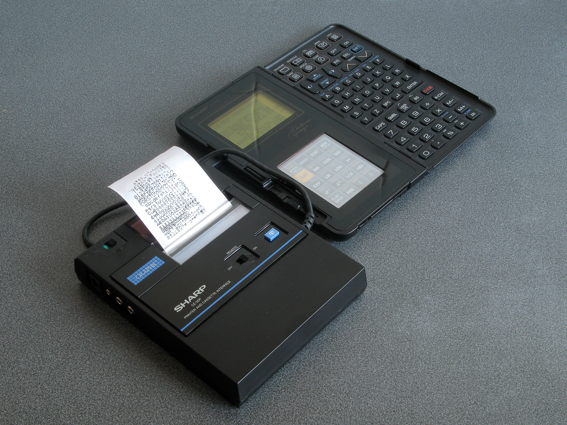
The result of running the test program on the IQ-7000: a printout of the CE-50P's full character set.
From that I was able to export a bitmap that I could then turn back into binary data for my CE-50P emulator, and I could then run the test program on the organiser again to check that the output from the emulated printer properly matched the output from the real one. I found some misplaced pixels by overlaying a screenshot of the virtual CE-50P's output over the scan and quickly flipping between them; once these were corrected, I was pretty happy that I had a decent version of the CE-50P's character set.
I did run into one further quirk of the printer; its output is 128 pixels wide, which can accommodate up to 21 characters per line, but the EL-9000 only prints 16 characters per line (as does my test program above). When I tried printing 21 characters nothing happened – indeed, any attempt at printing 17 or more characters in a line resulted in a silent printer. On a hunch I tried changing the printer command code from 0x51 to 0x52, and found that that allowed me to print up to 21 characters, as did 0x53. I'd previously allowed my emulated CE-50P to print any number of characters per line, but following those experiments I limited 0x51 to sixteen characters and 0x52/0x53 to 21, as per the behaviour of the real printer.
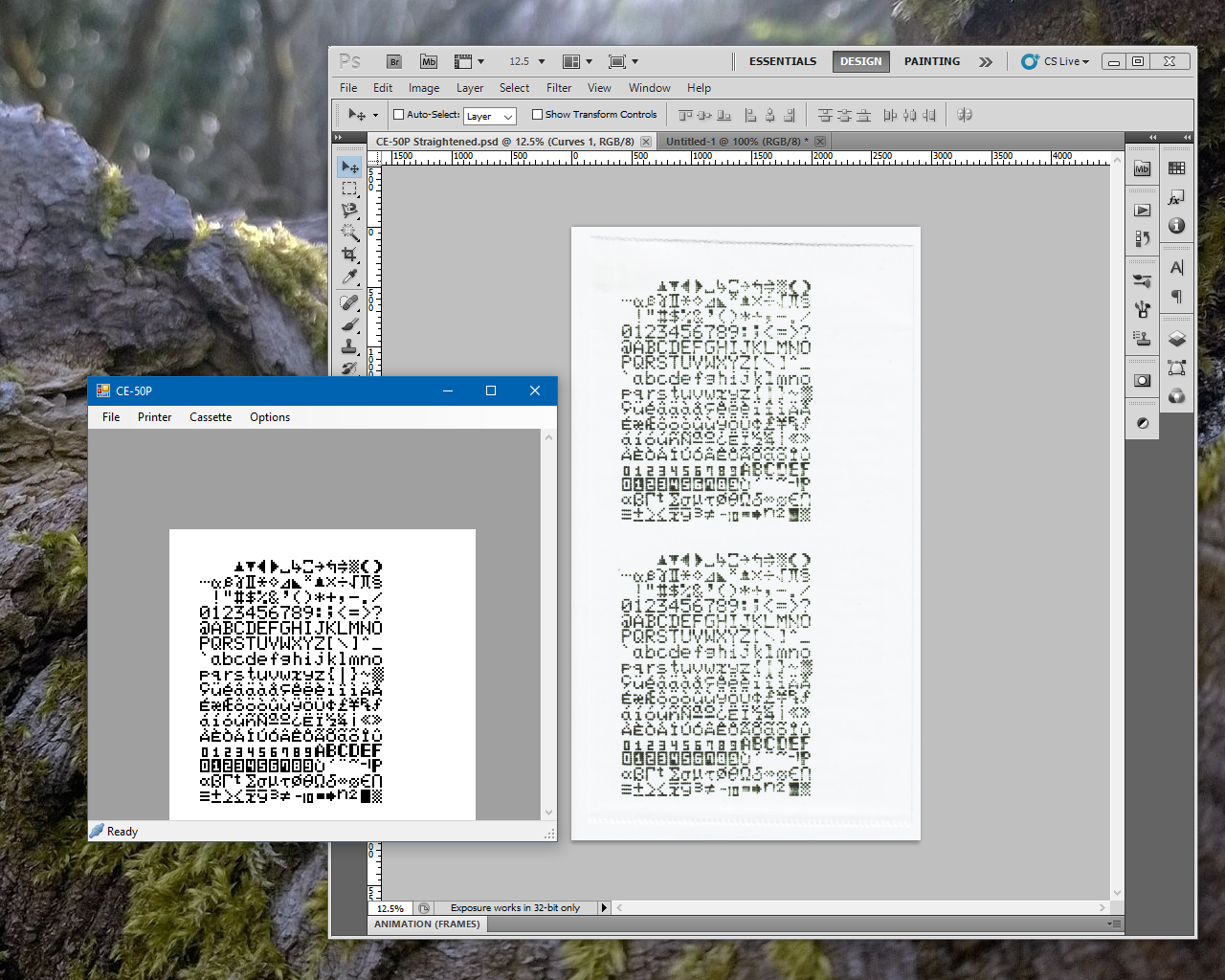
Comparing the virtual printer's output with the scans from the real one.
Now that I have a solution to the CE-50P's undocumented character set, maybe I can get to work implementing the rest of the EL-9000's data transfer protocol. Once I've finished that, maybe I can finish working on the EL-9300's equation editor. Once that's working to my satisfaction, maybe I can extend it for use in my EL-9400/EL-9450/EL-9600/EL-9900/EL-9950 link software. And then, if I'm very lucky, I might have something I could release... if I don't get sidetracked by something else in the process!
Subscribe to an RSS feed that only contains items with the EL-9300 tag.