Cogwheel 1.0.3.0 beta 3
Monday, 24th August 2009
I managed to break save states in the last build of Cogwheel (attempting to load a save state would fail, not being able to set a property). I've marked the offending read-only property with [StateNotSaved] and made the loader slightly more robust in Cogwheel 1.0.3.0 beta 3. It's beta 3, not 2, because I uploaded 2 and then noticed another issue - you couldn't change the controller mappings! This is something that must have been broken for ages, but either nobody noticed or they just didn't care to report it. Oh well, that's been fixed now. For some reason Google don't let you re-upload files, so beta 3 it has to be.
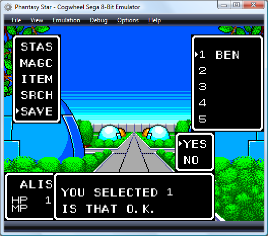
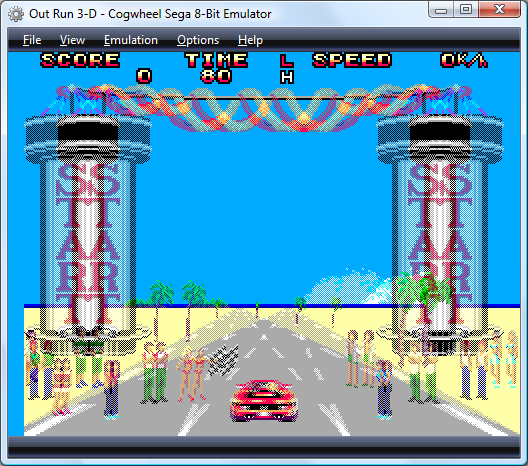
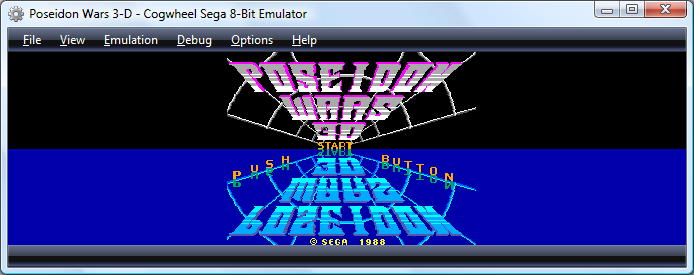
Another addition is this build is preliminary support for persistent cartridge RAM. Some games, such as Phantasy Star (pictured above) let you save your progress in the game onto battery-backed RAM built into the cartridge. If you come back to the game later you should now be able to continue your progress without needing to manually save the entire emulator state.
I've had reports of rather bizarre crashes bringing one poor user's machine to its knees. I'm at a loss to establish why; I've tried the emulator on four machines (two Vista, two XP) and although one of the machines displays a white screen instead of the emulator output (no pixel shader 2.0 support on its Radeon 9000) the software trundles along just fine otherwise (I can at least hear the game music!) The one notable difference between my machines and his machine is that he's using a 64-bit version of Windows, and all of the ones I have access to run 32-bit Windows. To see if this is the issue, I've changed the configuration to x86 (I've encountered strange bugs with .NET code using unmanaged 32-bit code on 64-bit Windows) to see if this will remedy issues, but if anyone has any bright ideas I'd be interested to hear them.
Cogwheel 1.0.3.0 beta 1
Thursday, 20th August 2009
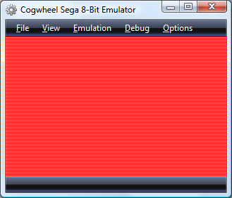
I've released a beta version of Cogwheel 1.0.3.0 in the hope of getting some feedback. My main concern is with the new 3D glasses code, so I'd be very grateful if you could install the emulator and run this ROM in it. The ROM simply alternates between showing a red screen for the left eye and a cyan one for the right eye (the emulator defaults to only showing the left eye, so you'll just see red for the moment). If you select a different 3D glasses mode (Options, 3D glasses, Row interleaved) you should end up with something like this:
If you drag the around the desktop the lines should appear fixed on the spot (as long as you drag it slowly enough to allow it to repaint), and if you resize it the entire form should always be covered in lines one pixel apart. The same should apply to the column interleaved and chequerboard interleaved modes.
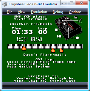
I've also added VGM recording and VGM playback. VGM playback is handled by bundling Maxim's SMS VGM player.
The console's region (Japanese or Export) and video standard (NTSC or PAL) are now user-configurable via the Emulation menu. The YM2413 (FM sound) emulation has been converted to straight C# (it used to be a P/Invoked native DLL). Drag-and-drop support has been added to aid in loading ROMs, save-states and VGMs.
There have been a number of internal optimisations, fixes and tweaks (such as per-scanline backdrop colours), but nothing too major (compatibility is roughly the same as it was). If you do find any bugs, please report them!
New 3D renderer in Cogwheel
Monday, 10th August 2009
I have written a new 3D-compatible renderer for Cogwheel. It holds two textures, one for each eye, and uses one of a number of different effect file techniques to mix the two views.
Based on the interlacing work from the previous entry, the first technique is one that uses interleaved rows. I'm not really sure if there's a good way to convert texture coordinates into device coordinates, so am passing in the viewport height as a parameter and hoping that floating point errors don't trip me up (they haven't, yet).
float4 RowInterleavedPixelShader(VertexPositionTexture input) : COLOR0 {
	float row = input.Texture.y * ViewportHeight * 0.5f;
	if (abs(round(row) - row) < 0.1f) {
		return tex2D(LeftEyeSampler, input.Texture);
	} else {
		return tex2D(RightEyeSampler, input.Texture);
	}
}
Alternate pixel centres may also pose a problem in the future. If anyone had any recommendations, suggestions or warnings on the way I'm detecting the evenness or oddness of a particular "scanline" then I'd appreciate hearing them!

I have also added two other interleaving modes; one in columns and another in a chequerboard pattern. I included these two as I've seen that some 3D LCD panels use a column interleaving pattern (I suppose that with a lenticular lens in front of such a panel you may not even need 3D glasses) and apparently Sharp have displays that use the chequerboard pattern.
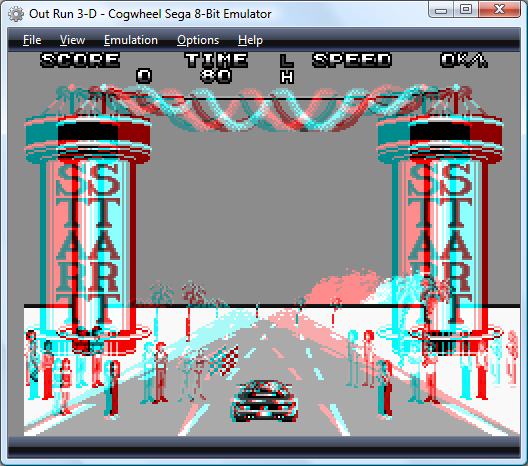
I have also taken advantage of pixel shaders to create colour and monochrome anaglyphs (previously calculated in software), though neither look as good as the above full-colour modes for shutter glasses or similar hardware.
There are a few issues I need to sort out first before I can release this; for example, there's no way to set whether the first row/column/pixel is for the left or right eye. More problematic is the removal of support for non power-of-two textures; the Master System's 256×192 display is fine, but the Game Gear's 160×144 display gets rounded up to 192 pixels wide (and yes, I know that's not a power of two) on my video card. I also mean to give Promit's SlimTune profiler a look to see if I can optimise some of the less efficient pieces of my code. The C# version of emu2413 is probably a good candidate, being a "dumb" translation from the original macro-heavy C.
Taking advantage of interlacing for 3D
Friday, 7th August 2009
To achieve smooth, glitch-free 3D in an ideal world, one would like to be able to alternate between left and right eye views every time the monitor refreshes. You could then use the monitor's vertical synchronisation pulse to alternate which eye shutter is currently open.
Relying on software is not so bad if you can guarantee that you will be able to keep up with the video hardware and output alternating frames without dropping any. This is pretty much impossible with today's complex operating systems running any number of background tasks that could interfere with your render loop at any moment.
Fortunately, video cards already have a mode that is guaranteed to output a different image every frame - interlaced scan. Rather than send each scanline (row) of the image every frame ("progressive scan"), it alternates between sending every even-numbered scanline and every odd-numbered scanline. This halves the vertical resolution, but allows you to double the refresh rate using the same amount of bandwidth.

We can take advantage of this scan mode to encode the left and right views into a single image. The view for the left eye is stored in the even-numbered scanlines and the view for the right eye is stored in the odd-numbered scanlines, as in the image above. When displayed on a monitor using interlaced scan, it appears as the following:
As the video card takes care of alternating which set of scanlines (or field) is displayed, the result is that the left and right views alternate perfectly in time with the monitor's refresh rate.
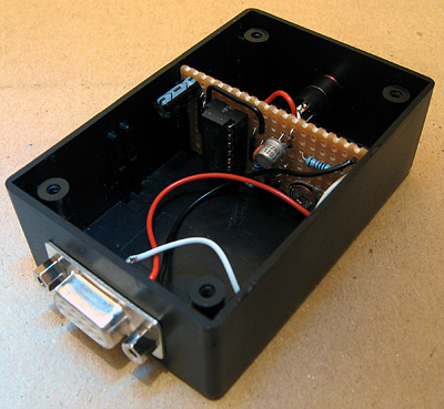
To test this, I've attached a counter IC to the vertical synchronisation pulse of a VGA monitor. The low bit of the counter toggles every time the screen refreshes, and this is used to select which eye shutter is open on the 3D glasses. The glasses are driven using the serial port adaptor described in the previous post.
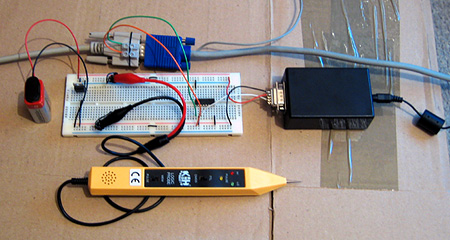
The result is perfectly stable 3D images. The circuit does not know which field, and hence which eye's view, is visible at any time - it just alternates left and right, which means that there is a 50% chance that the left and right views are flipped. This can be fixed by switching the circuit off then on again to try and resynchronise, but a better solution would be to add a switch to toggle the uncovered eye manually and to fix the synchronisation. As this would only need to be done once per session this isn't much of an issue! An alternative fix would be to add a switch to switch the left and right views in software.
The logic probe in the above photo is an integral part of the design - at least, I assume it is, as if I remove it the circuit doesn't work correctly! I assume there's a noise issue that's interfering with the circuit (none of the unused inputs on the counter chip are tied low) and the logic probe contains some noise suppression circuitry of its own.
The only real fly in the ointment here is video driver support for interlaced scan modes. My video card only supports 1920×1080 at 30i, 29i and 25i, and only if the primary monitor is an LCD. I can work around the problem by cloning the primary LCD to the CRT and setting both to 1920×1080 at 30i, but my LCD displays a warning message and makes a distressing noise and 30i, whilst faithful to the Master System's 30fps 3D, is unpleasantly flickery. It would be wonderful if I could drop the resolution down a bit and switch to 60i, but I can't see a way to do that with ATi's drivers.
3D LCD Shutter Glasses Experimentation
Wednesday, 5th August 2009
The Sega Master System supported 3D LCD shutter glasses to provide a more immersive (if somewhat flickery) playing experience. Having caught wind of an eBay member selling compatible glasses for $9 and being rather interested in stereoscopy I decided to experiment a little for myself.
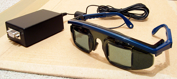
The glasses are pretty simple; they consist of two LCD panels that can be "switched on" to block light from passing through to each eye. A 3.5mm stereo jack plug provides the electrical connection.
To display the 3D image you alternate between showing the image for the left eye and the right eye on the monitor, uncovering the corresponding eye immediately before the image appears on the monitor. This effectively halves the refresh rate (and results in fairly noticeable flicker when run at the standard NTSC 60Hz) and prevents the 3D glasses from working with displays that respond too slowly (eg LCD panels). I've had to dig out my old CRT monitor for this project. Even if my LCD did refresh quickly enough, its polarisation is perpendicular to the polarisation of the shutter glasses, meaning that no light can pass from the LCD through the glasses even when both eye LCD panels are switched off.
The adaptor I'm using is based on this circuit (I'm using the second variation with the variable resistor to fine-tune the driving frequency). The LCD panels require an AC voltage, and using a EOR gate as an oscillator allows the whole device to be constructed out of a single IC with a handful of external components. More importantly, being based on an existing and public design allows me to ensure that any work I do should be compatible with adaptors other people have built.
The DTR pin on the serial port supplies power to the circuit and the RTS pin is used to choose which LCD panel is switched on to cover an eye.
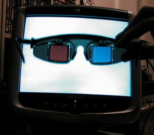
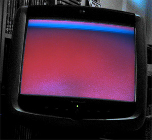
Test pattern seen through glasses
The above image displays a test pattern viewed through the glasses. The software alternates between clearing the screen to red with the left eye shutter open and clearing the screen to cyan with the right eye shutter open. The colours were deliberately chosen to match the colours of the common anaglyph glasses. As the colours are alternated very quickly (in the interests of avoiding a headache I used a refresh rate of 120Hz) the screen appears a light grey colour to the naked eye.
Most LCD shutter glasses appear to use some form of feedback from the video signal to synchronise the alternating of eyes. On a PC they could alternate every time the vsync signal appeared on the VGA port, on a TV they could open the correct eye shutter depending on the current field of the interlaced image that was being displayed. The Sega Master System's video chip can generate an interrupt when entering the vblank period which you can use to prepare the next frame and update the glasses. An adaptor connected to the PC's serial port has no such luck - I have not yet found a way to reliably synchronise the glasses to the refresh rate.
Poor synchronisation (and even worse photography) results in images like the above, as seen through the left shutter. As the LCD shutters have been updated too late, some of the display intended for the right eye is seen through the left eye at the top of the display - the cyan band in this case.
So far, the best result I've had is to use Direct3DEx's DeviceEx, which provides a handy WaitForVBlank method. Less handy is the Vista requirement, as is the slight delay between returning from this function and updating the serial port, resulting in a flickering band near the top of the display as per the previous photograph. For the best results I need to set the presentation interval to "immediate", which compounds the issue with occasional tearing caused by the delay between WaitForVBlank returning and calling Present.
Switching the presentation interval back to "1" (tying the refresh rate of the render loop to that of the monitor) results in complete frames (no tearing or bands of the wrong colour/image), but the additional delay before presenting the next frame puts updating the LCD glasses out of sync by one frame. As the uncovered eye should alternate between subsequent frames one can simply uncover the "opposite" eye to uncover the correct image, but any dropped frames throw this out of sync and you get the occasional "inside out" view when the wrong eye is uncovered. Any background tasks on the PC kicking in could potentially cause a dropped frame. This is one reason that a VGA pass-through adaptor that automatically alternates the uncovered eye every frame wouldn't work, as it would get thrown out of sync by these dropped frames.
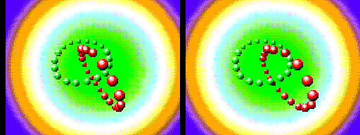
A demo compatible with the Sega 3D glasses, showing the images for each eye as stereo pair
The advantage of using an existing adaptor design makes me reluctant to pursue solutions that involve additional hardware to fix the problem. One possible solution I can think of would be an additional pass-through box that contains a simple latch that is clocked by the VGA vsync signal between the serial port and the glasses adaptor. You could then set the state of the glasses immediately before calling Present, safe in the knowledge that your signal will only get through to the adaptor box perfectly synchronised with the CRT's vertical refresh, assuming the CRT doesn't enter vblank between updating the serial port and calling Present. Not having to manually synchronise to vsync in software would remove the need for the Vista-only Direct3DEx too.