Mounting circuit boards and rear panel connectors
Monday, 9th August 2010
One of the fun things about working with electronics is that you can end up with a physical product at the end of your hard work. To this end I have started moving my Z80 computer from its current breadboard to a more permanent enclosure.
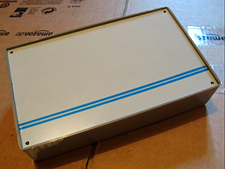
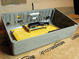
Large project boxes can be quite expensive (around £40, it seems), but the one I picked out was a slightly more reasonable £7. It's not the prettiest enclosure I've seen but it should be large enough to house the computer and provide space on the lid for the LCD and on the rear surface for a collection of connectors (as you'd expect to find on the rear of any computer).
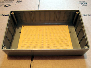
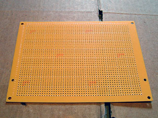
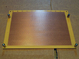
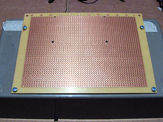
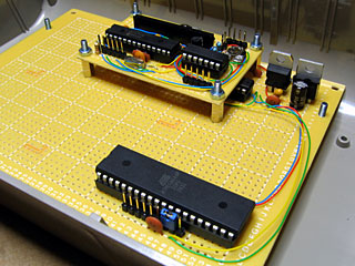
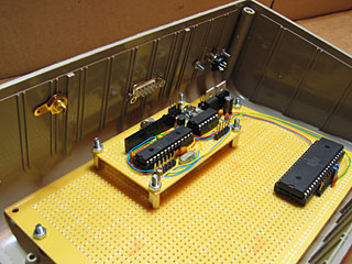
The first challenge was how I intended to mount the circuit board within the box. The perfboard I will use for the main computer circuit doesn't fit the marked mounting posts on the bottom of the project box; it's too narrow and too deep. What the photo doesn't show very well is that the perfboard is not able to lie flat in the box due to the curve at the rear of the box. To raise the board above the bottom of the box I decided to use four PCB spacers, which required two new holes to be drilled into the perfboard away from its corners.
I decided that the video display controller, which resides on its own board, should be mounted on the main circuit board using PCB spacers too.
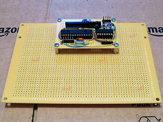
This required four more holes to be drilled into the main circuit board. I tried to align the small video display board so that its 16-way pin socket for connection to the LCD was as close to the horizontal centre as possible.
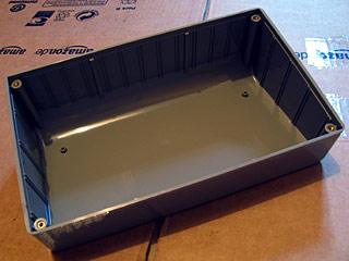
The base of the project box needed to have four holes drilled into it to support the main circuit board. Once the two nearest the front edge had been drilled, I screwed the circuit board to the back of the project box to mark the position for the other two holes to ensure that they lined up exactly with the holes drilled in the circuit board.
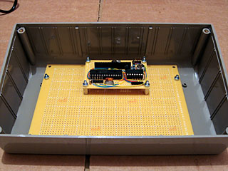
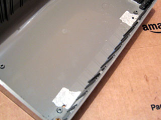
Screws come through the bottom of the project box to hold the main circuit board in place. Some sticky foam feet are provided with the project box which will raise it off the surface it is resting on to prevent these four screws from leaving scratches! Due to the curve at the back of the box the circuit board is only a few millimetres above its surface, which is why I reversed the screws holding the video display board to leave the long threaded ends pointing upwards.
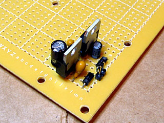
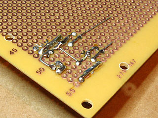
As working on the enclosure is a fairly noisy activity I switched my attention to the electronics for a brief spell. The first part of the circuit I assembled was the power supply; this just uses a pair of voltage regulators to provide 5V and 3.3V from an external power supply (I use a cheap wall wart affair rated at 7.5V DC).
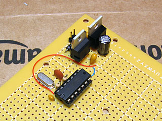
I decided that the next part to tackle would be the oscillator. This uses a 20MHz crystal and a 74LS04 according to the design on z80.info to generate a 20MHz clock signal which will be further divided by two to produce a 10MHz clock signal for the Z80. I had some real problems with this design; it would run at 20MHz until I attached a load to it, at which point it would generate a fairly random-looking signal or stop oscillating entirely. I experimented with a few different capacitors and found that if I remove the 120pF capacitor and replace it with a 33pF capacitor on the other end of the crystal it works reliably. I'm not entirely sure why this is, but it's the design I've been using for a while with the computer on a breadboard so I'm happy to keep it this way for the time being.
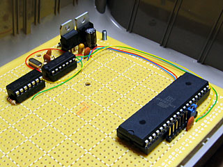
I added a D flip-flop to divide the 20MHz clock to 10MHz and then added the ATmega644P microcontroller to the board. This has a jumper next to its clock input allowing for the selection of either 20MHz or 10MHz operation; a pin header to the left of this jumper allows for it to be programmed in-circuit.
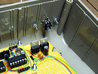
With those new parts in place I reinstated the video display board to check that everything still fit. My main concern now was how far the connectors screwed into the rear of the case would intrude and whether there'd be any problems with them getting in the way of the circuit boards.
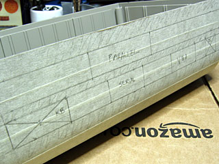
I sketched a design of how I saw the connectors would fit on the back of the case and then copied the layout to some masking tape stuck to the case. The computer naturally needs a power supply and keyboard input, and the video display board accounts for the VGA connector and an RCA connector for composite video (which I neglected to mark). I also hope to include a serial port and a parallel port in the final design (though neither are currently supported by the software) so left space for those two connectors.
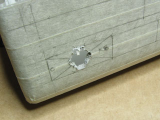
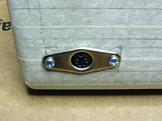
The 6-way mini-DIN connector for the keyboard is the deepest one to contend with so I decided to start with it. I cut the hole in the case by drilling a small hole in the plastic which I then enlarged with a burr tool to the correct shape and size.
Fortunately it looks like there's plenty of room in the case for connectors!
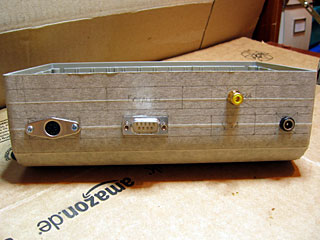
The next few connectors confirm this. I really do not enjoy cutting the holes for D-sub connectors (such as the one for the serial port); they don't have much of a metal lip to hide a botched hole, so I have to cut very slowly and very carefully, taking a very long time to slowly enlarge each hole until the connector fits. I'm therefore not really sure why I decided to have three D-sub connectors in this computer design; maybe I'm just a glutton for punishment.
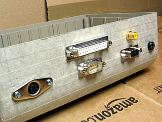
Finally, the rear of the case is completed. I will leave the masking tape on there as scratch protection until I have finished the front of the case (this will be significantly simpler — just a power switch, power LED and disk activity LED). Once that is done I can resume working on the electronics!