Targeted repairs for missing rows and columns on the Sharp EL-9900's LCD
Wednesday, 2nd September 2026
Sharp don't seem to have the best reputation when it comes to graphing calculators however I do have a bit of a soft spot for them as they do have some interesting features. The EL-9300 lets you connect a printer and cassette interface to print out screenshots, program listings or formulae as well and save data to (and load data back from) tape cassette. The EL-9600 has a touch screen which does rather speed up menu navigation. The EL-9900 loses the touch screen but has a reversible keyboard with a "basic" side and an "advanced" side, which changes available menu options and defaults as well as the keyboard layout.
Unfortunately, the EL-9900 seems to suffer from the flex cable that connects the main PCB to the LCD coming unstuck, resulting in an increasing number of missing rows and columns as it ages. Fortunately, there is direct access to the flex cable on the EL-9900 calculator, which means it can be reattached by reheating it.
I have four EL-9900 calculators now and all had this issue. The first one I repaired by gingerly poking around with a soldering iron (set to around 250°C) until all the rows and columns came back. The next one I repaired in a video for YouTube and I dealt with that one by working my way along the whole flex cable from left to right until everything was working. Not exactly a scientific approach, but with so many missing columns I figured the cable needed some serious attention anyway and that calculator is still fully working 20 months later.
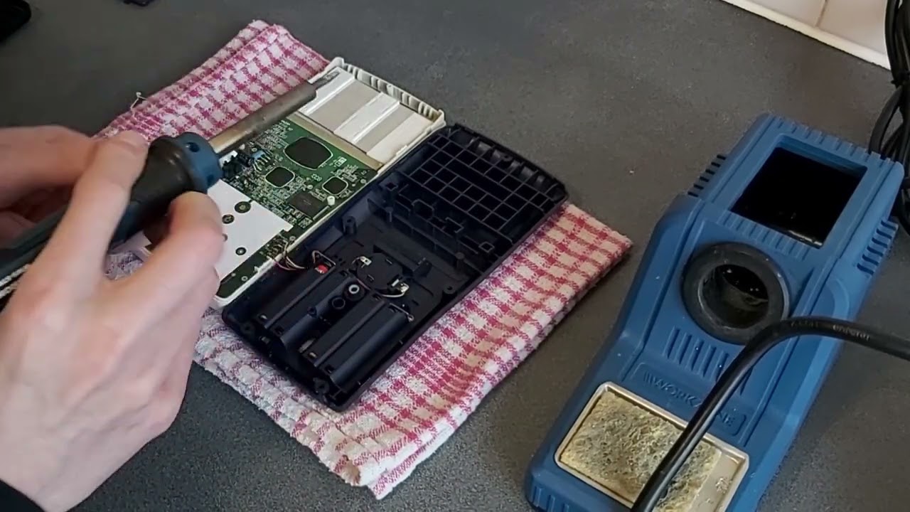
The first calculator I tried to repair didn't fare so well, unfortunately. After the initial success it started losing rows and columns again and so I'd try re-heating the flex cable. That would work for a week or so until yet another row or column disappeared. Eventually I had reheated the cable so many times it started to look very crusty and the repairs became less effective, until I ended up melting a hole straight through a section of it, destroying it completely.
I recently acquired another pair of EL-9900 calculators, both with only two or three missing rows and columns on them. I thought it would be a good opportunity to try a more targeted approach, as reheating the whole flex cable when there were only a small number of faults seems unnecessarily risky. There are two issues here: identifying which rows and columns are faulty, and then identifying where the corresponding point on the flex cable is to heat with the soldering iron. To this end, I developed this printable guide (LibreOffice Draw file) that has three rulers on it.
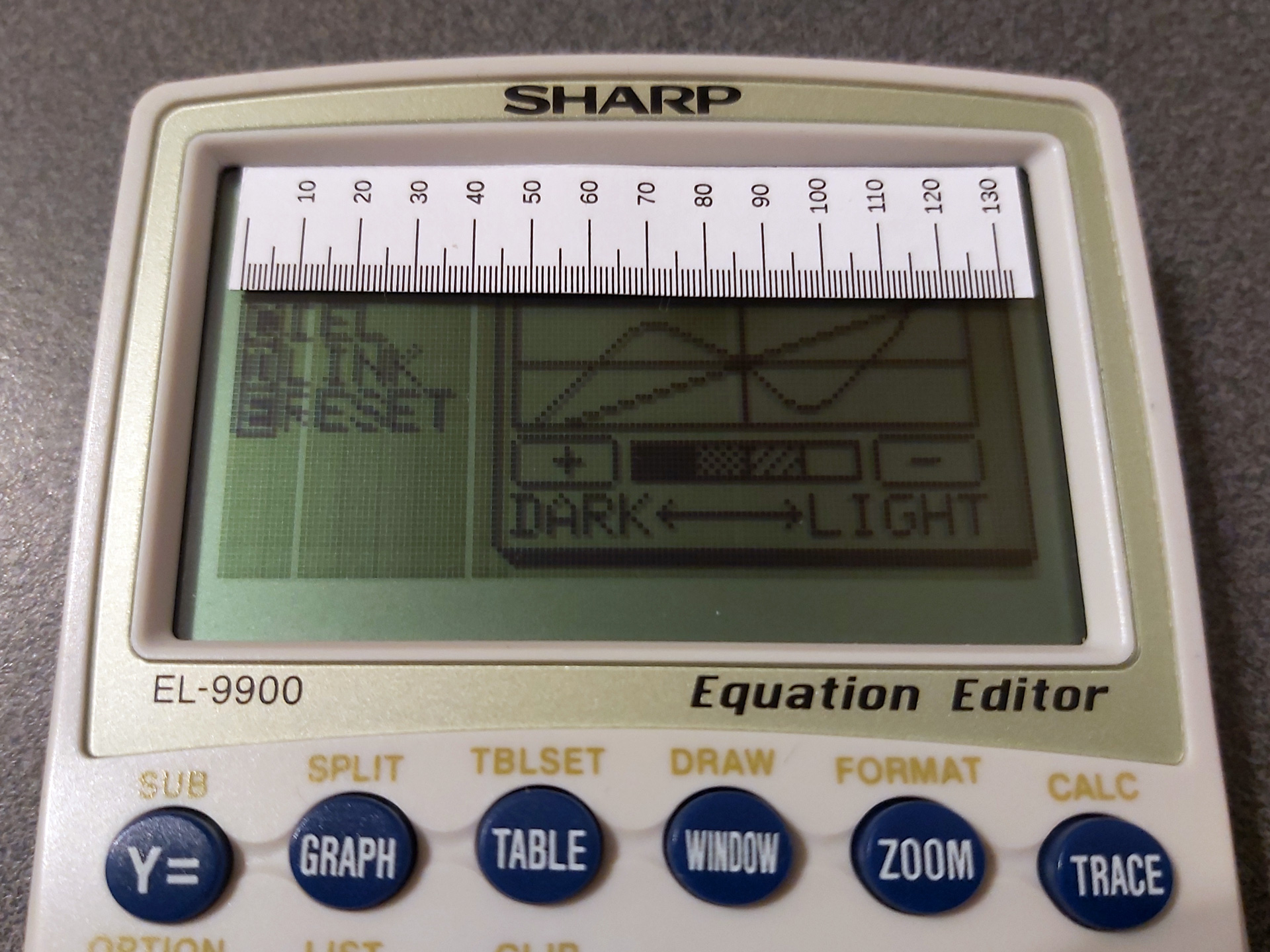
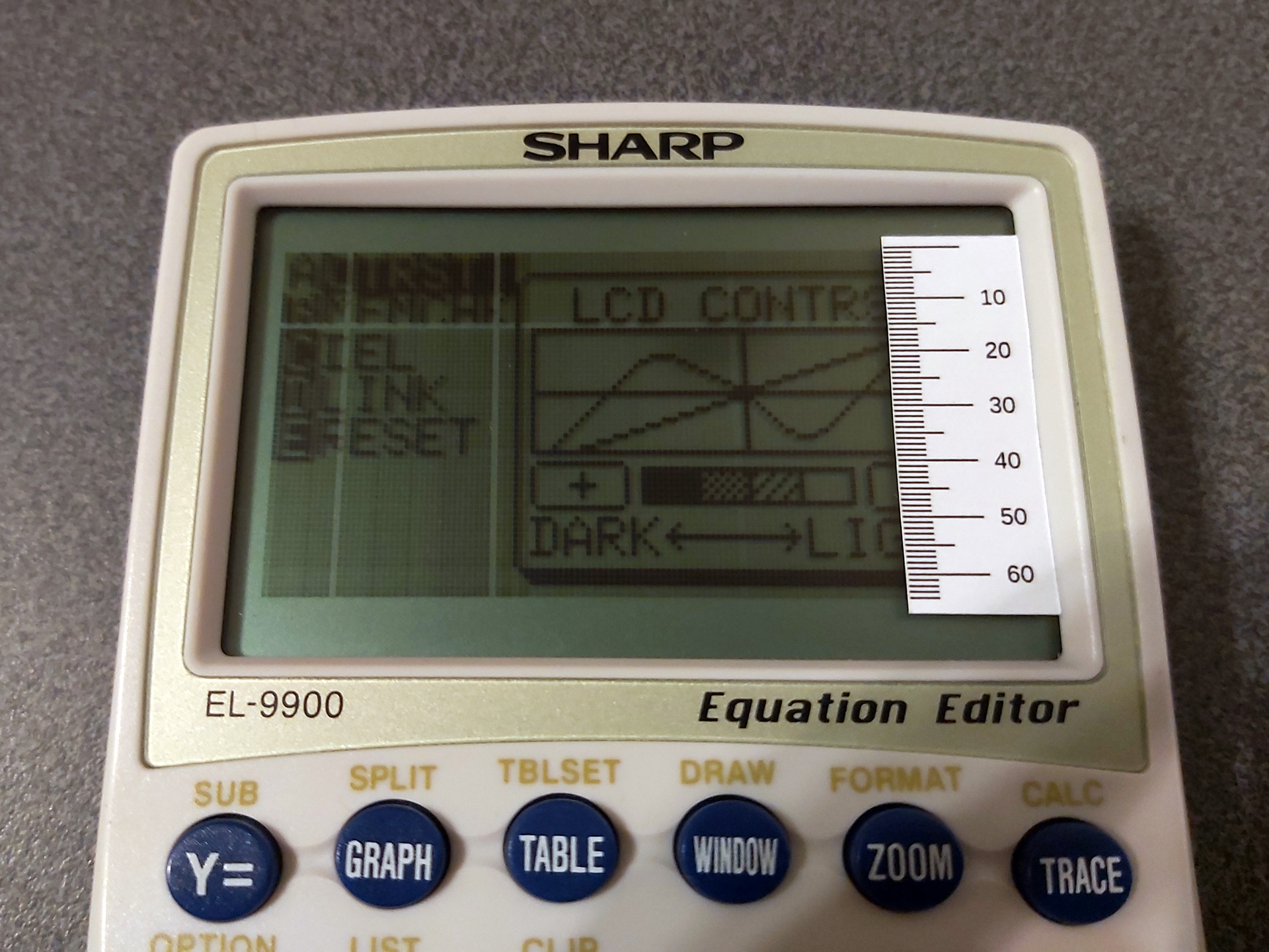
The first two rulers can be used to measure the column or row number of the missing pixels. You could just count these, but that can quickly get very tedious! The third ruler can then be used to find where to heat up the flex cable:
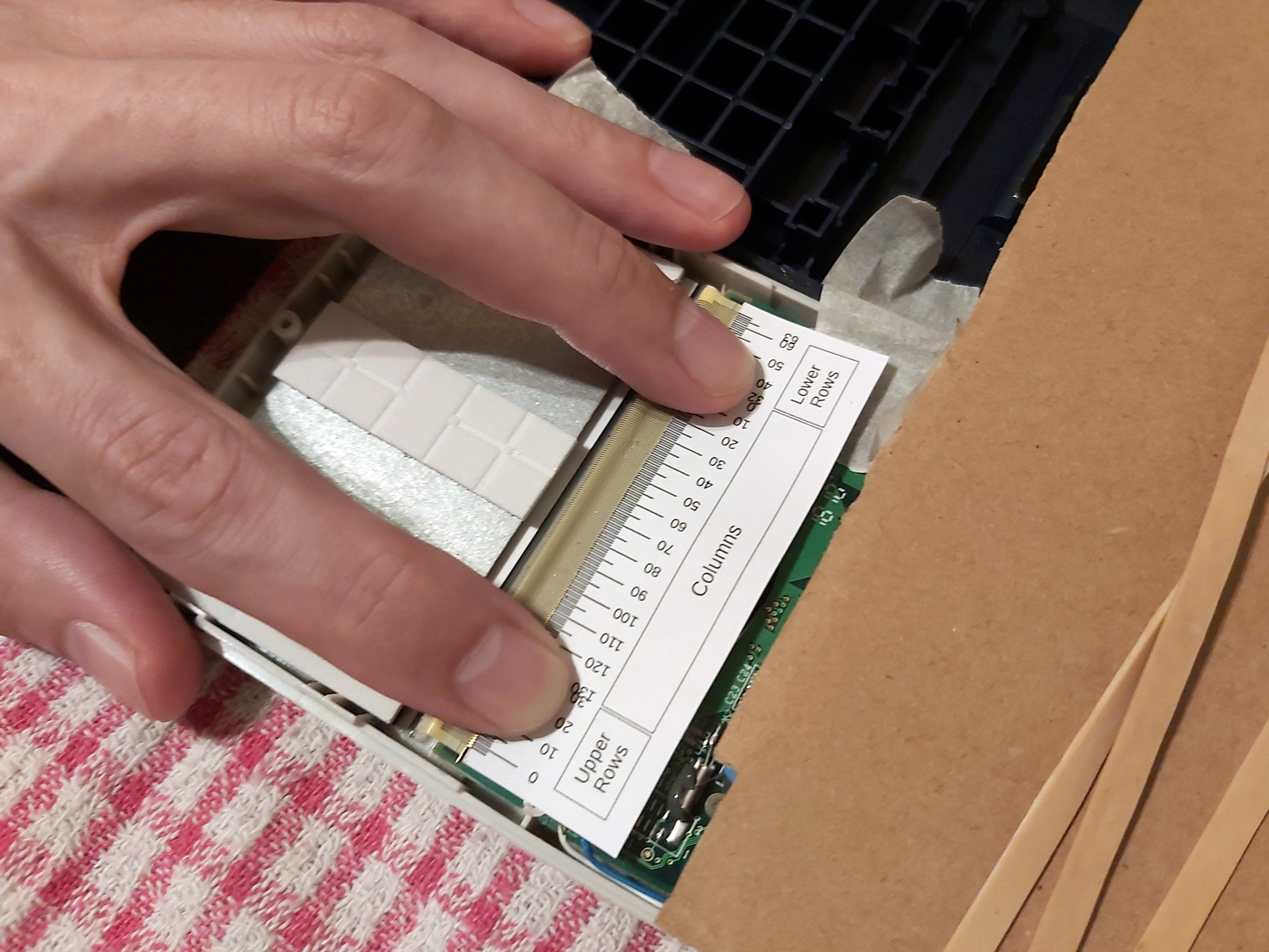
Note that the "Lower Rows" are – I think – incorrectly ordered in this photo.
The flex cable can be broken down into three areas. The large central area corresponds to the columns, though as we are working on the back of the LCD the column numbers are reversed (and so run from right to left, rather than left to right). The left hand side of the flex cable corresponds to the top half of the display and the right hand side corresponds to the bottom half. I worked this out by removing the LCD from the calculator I'd previously destroyed and holding it up to a bright light to see where the traces in the glass went. Fortunately for me but unfortunately for testing purposes the LCDs in the calculators I've repaired have only had faulty rows in the upper half of the display, which means that I initially got the order of the "lower rows" reversed – having sketched it out on some paper I think the middle row (32) will be connected on the outside of the flex cable and the bottom row (63) will be on the inside, nearest the "columns" section, as otherwise the traces would have to cross over each other. I have updated the PDF and ODG, but that explains the error in the above photo, and until I find a calculator with a fault in the lower half I won't be able to double check.
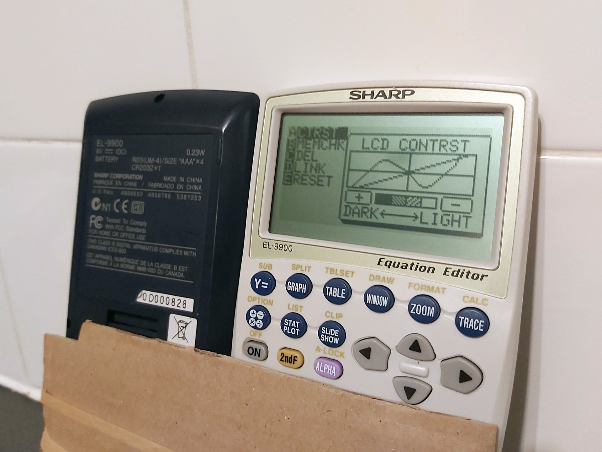
All the rows and columns are back, but sadly I can't do much about the LCD "bruise" below the C in CONTRST.
I was able to use the guides to successfully repair the two recently-acquired calculators by only heating the affected parts of the flex cable. I also used a lower temperature on the soldering iron than before (220°C) and that seemed to be enough to stick the cable back down – I'd only hold it against the flex cable for a short amount of time, lightly running it down the cable in the direction of the traces and then holding the flex against the PCB firmly with a finger as it cooled.
In case you found this post because you also have a faulty EL-9900 calculator and are looking for some repair tips, here's what springs to mind:
- The calculator has five main screws on the back as well as one smaller one inside the battery compartment under the third cell from the left. You do not need to remove the screw on the memory battery backup door.
- The case has four clips on the sides holding the two halves together. I find it easiest to unclip the first two from the top (the guide for the hard case widens at the top, giving you plenty of room to insert your fingers to pull, with the two clips being towards the bottom of the LCD). Squeezing the white front half of the calculator whilst continuing to pull will release the lower two clips. Do not fully separate the two halves yet, you just want to release the clips.
- There are four very thin wires between the rear half of the case (containing the battery compartment) and the front half of the case (containing the main PCB). The two halves of the case can be opened like a book with the opening on the right hand side when looking at the front of the calculator.
- As the battery compartment is connected with wires (rather than, say, spring contacts to the main PCB) the calculator can be operated when open. However, a switch on the main PCB (normally pressed by a stud on the battery compartment door) prevents this from happening – a piece of tape will hold this down and let you switch the calculator on.
- The connections for the thin wires between the battery compartment and main PCB are extremely fragile, so if you keep opening and closing the calculator when working on it these will likely break and need to be resoldered. To avoid this, I recommend only opening the calculator up once, then using some tape to join the two halves of the calculator together at the "hinge" and using two pieces of cardboard and an elastic band to hold everything together as this will let you flip the calculator over between working on the flex cable and checking the LCD without stressing those thin wires. The keyboard should also be popped out to prevent the cardboard from holding down the keys (the fixed keys above the removable keyboard are more than sufficient to test the calculator when working on it).
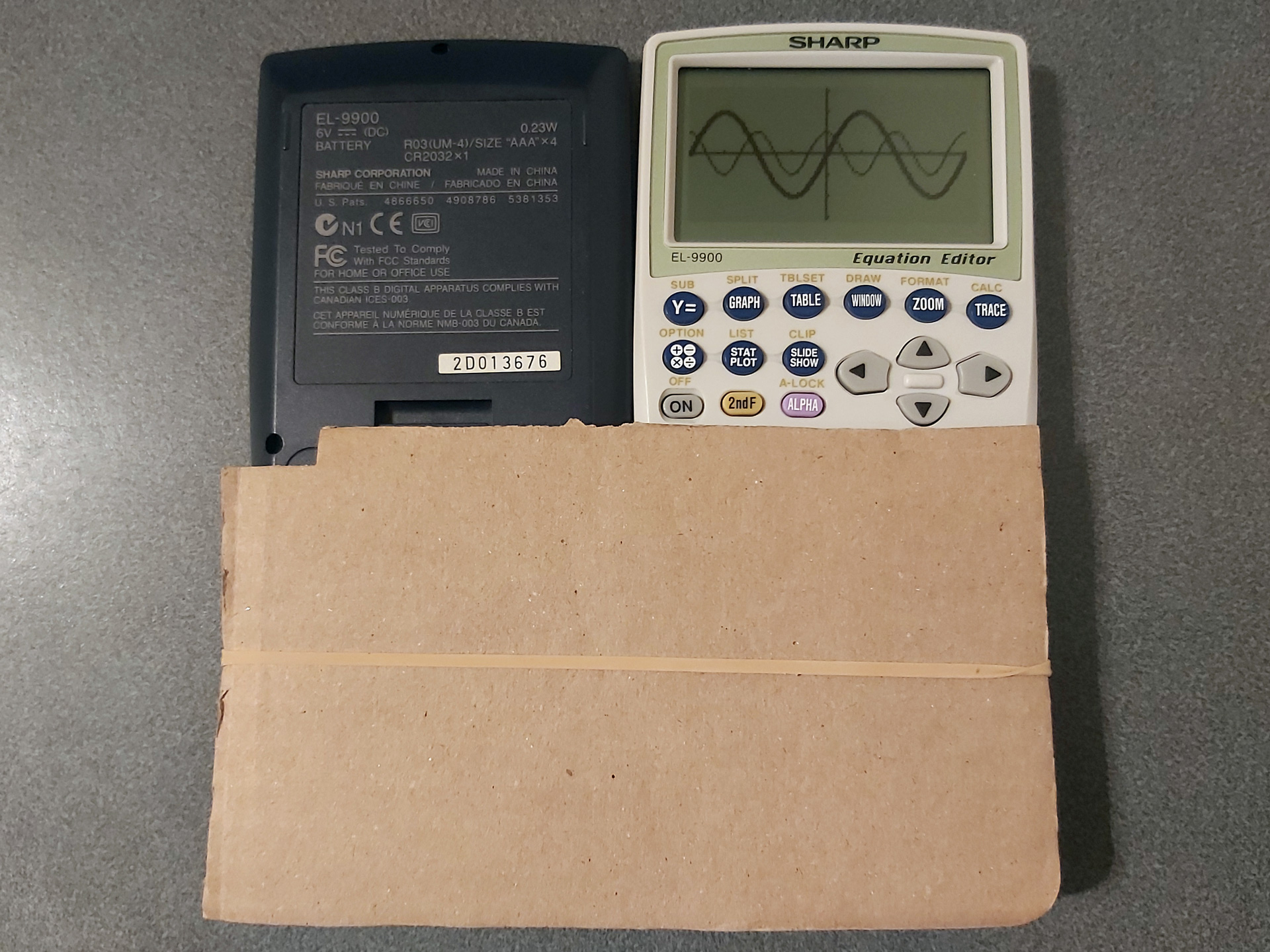
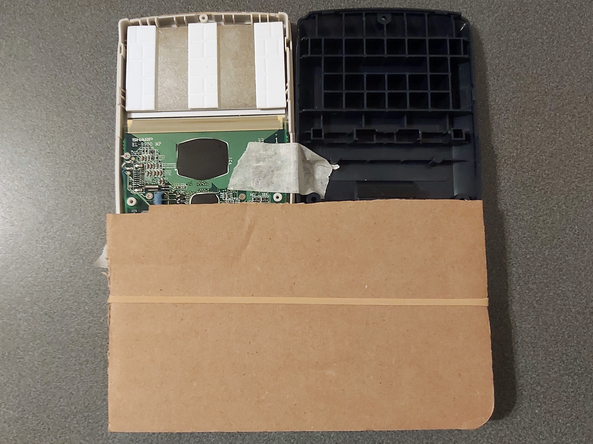
- Only poke the soldering iron near the part of the flex cable that's stuck to the board. The soldering iron will very easily melt a hole in the flex cable if you touch it in the unsupported gap between the PCB and the LCD glass.
- Once you've repaired any known faulty rows or columns, test the calculator over a period of a few hours before closing it back up in case the fixes don't hold or any new faults appear after disturbing the flex cable. Keep a list of rows or columns you've repaired to see whether the issue is one you've repaired before or whether it really is a new fault.
- When closing the calculator back up, it's much easier to do this without the keyboard installed due to the sprung pin that normally tries to push the keyboard out. I also find it easier to put the spring and pin in the back half of the calculator and to lower the front half on top of it (threading the pin through the small hole in the front) rather than balancing the pin with the spring on top of it in the front half and lowering the back half on top of that.
Here again is the link to the printable repair guide (LibreOffice Draw file), and maybe it'll help you if you have a faulty EL-9900. It's certainly helped me – good luck!