Targeted repairs for missing rows and columns on the Sharp EL-9900's LCD
Wednesday, 2nd September 2026
Sharp don't seem to have the best reputation when it comes to graphing calculators however I do have a bit of a soft spot for them as they do have some interesting features. The EL-9300 lets you connect a printer and cassette interface to print out screenshots, program listings or formulae as well and save data to (and load data back from) tape cassette. The EL-9600 has a touch screen which does rather speed up menu navigation. The EL-9900 loses the touch screen but has a reversible keyboard with a "basic" side and an "advanced" side, which changes available menu options and defaults as well as the keyboard layout.
Unfortunately, the EL-9900 seems to suffer from the flex cable that connects the main PCB to the LCD coming unstuck, resulting in an increasing number of missing rows and columns as it ages. Fortunately, there is direct access to the flex cable on the EL-9900 calculator, which means it can be reattached by reheating it.
I have four EL-9900 calculators now and all had this issue. The first one I repaired by gingerly poking around with a soldering iron (set to around 250°C) until all the rows and columns came back. The next one I repaired in a video for YouTube and I dealt with that one by working my way along the whole flex cable from left to right until everything was working. Not exactly a scientific approach, but with so many missing columns I figured the cable needed some serious attention anyway and that calculator is still fully working 20 months later.
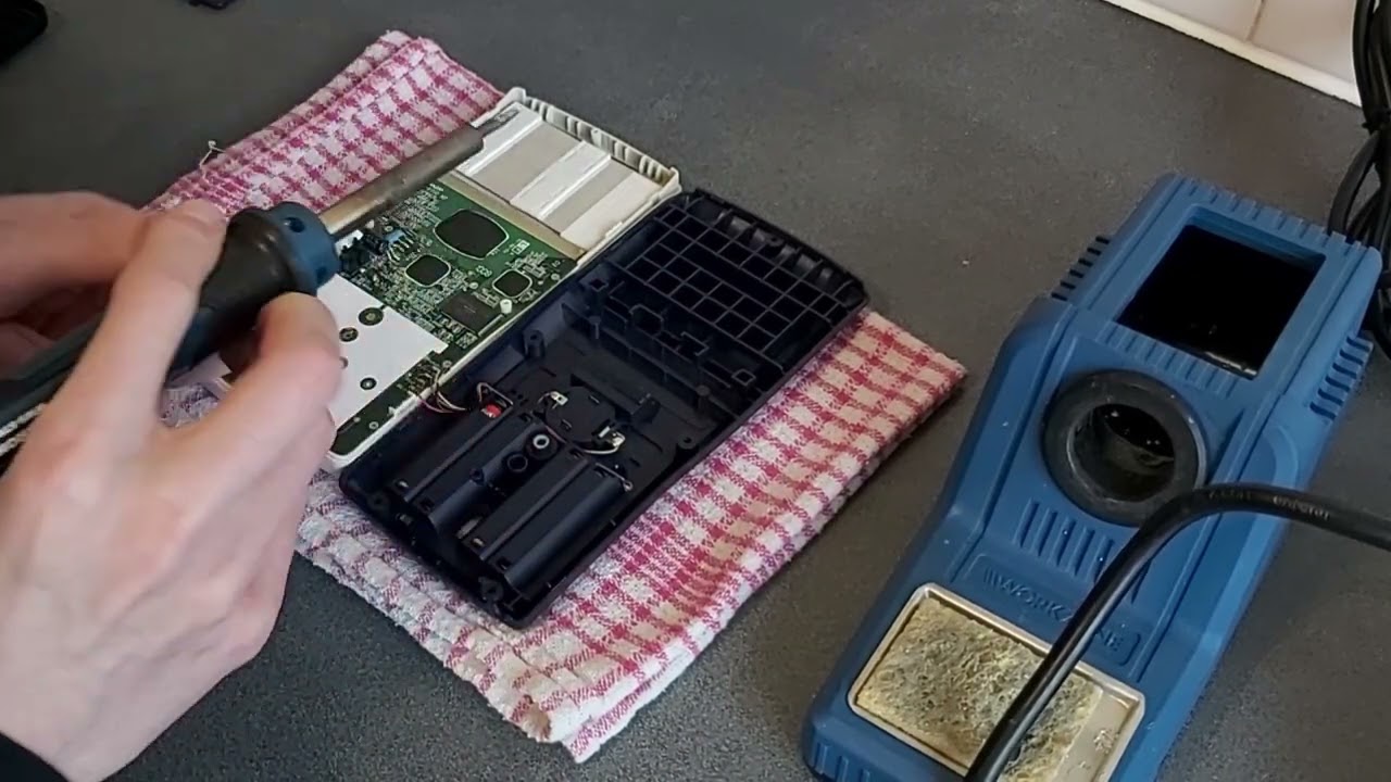
The first calculator I tried to repair didn't fare so well, unfortunately. After the initial success it started losing rows and columns again and so I'd try re-heating the flex cable. That would work for a week or so until yet another row or column disappeared. Eventually I had reheated the cable so many times it started to look very crusty and the repairs became less effective, until I ended up melting a hole straight through a section of it, destroying it completely.
I recently acquired another pair of EL-9900 calculators, both with only two or three missing rows and columns on them. I thought it would be a good opportunity to try a more targeted approach, as reheating the whole flex cable when there were only a small number of faults seems unnecessarily risky. There are two issues here: identifying which rows and columns are faulty, and then identifying where the corresponding point on the flex cable is to heat with the soldering iron. To this end, I developed this printable guide (LibreOffice Draw file) that has three rulers on it.
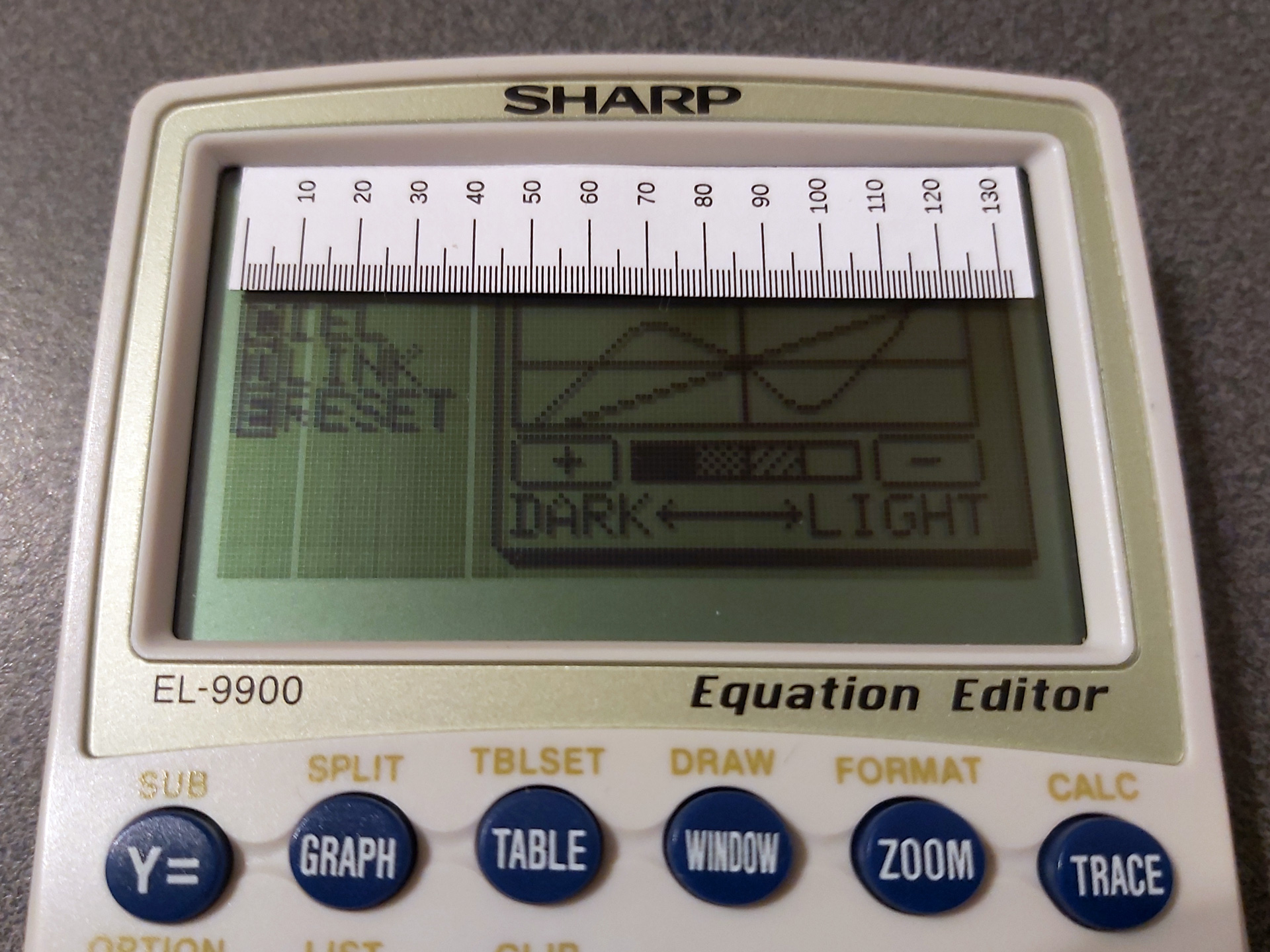
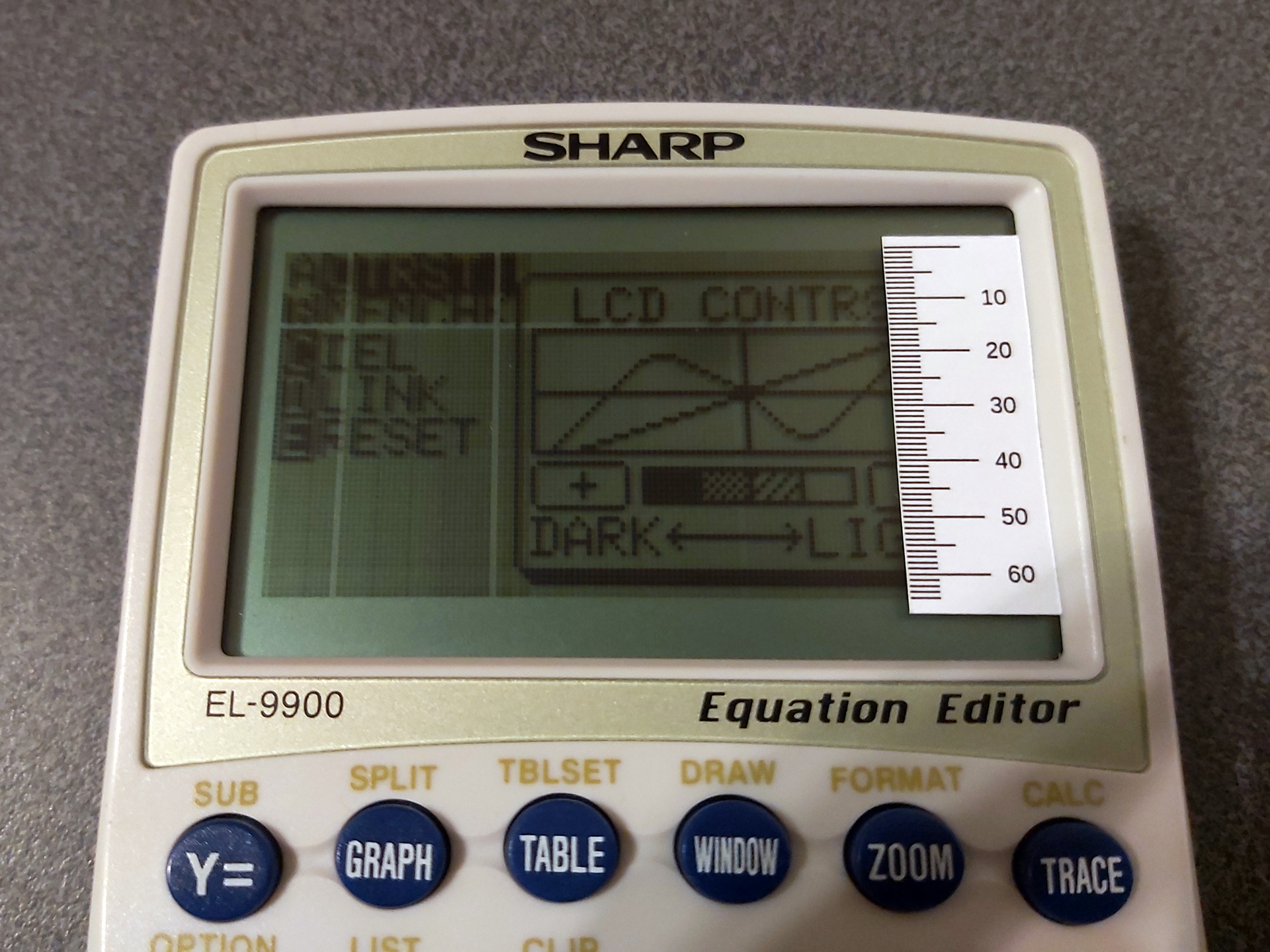
The first two rulers can be used to measure the column or row number of the missing pixels. You could just count these, but that can quickly get very tedious! The third ruler can then be used to find where to heat up the flex cable:
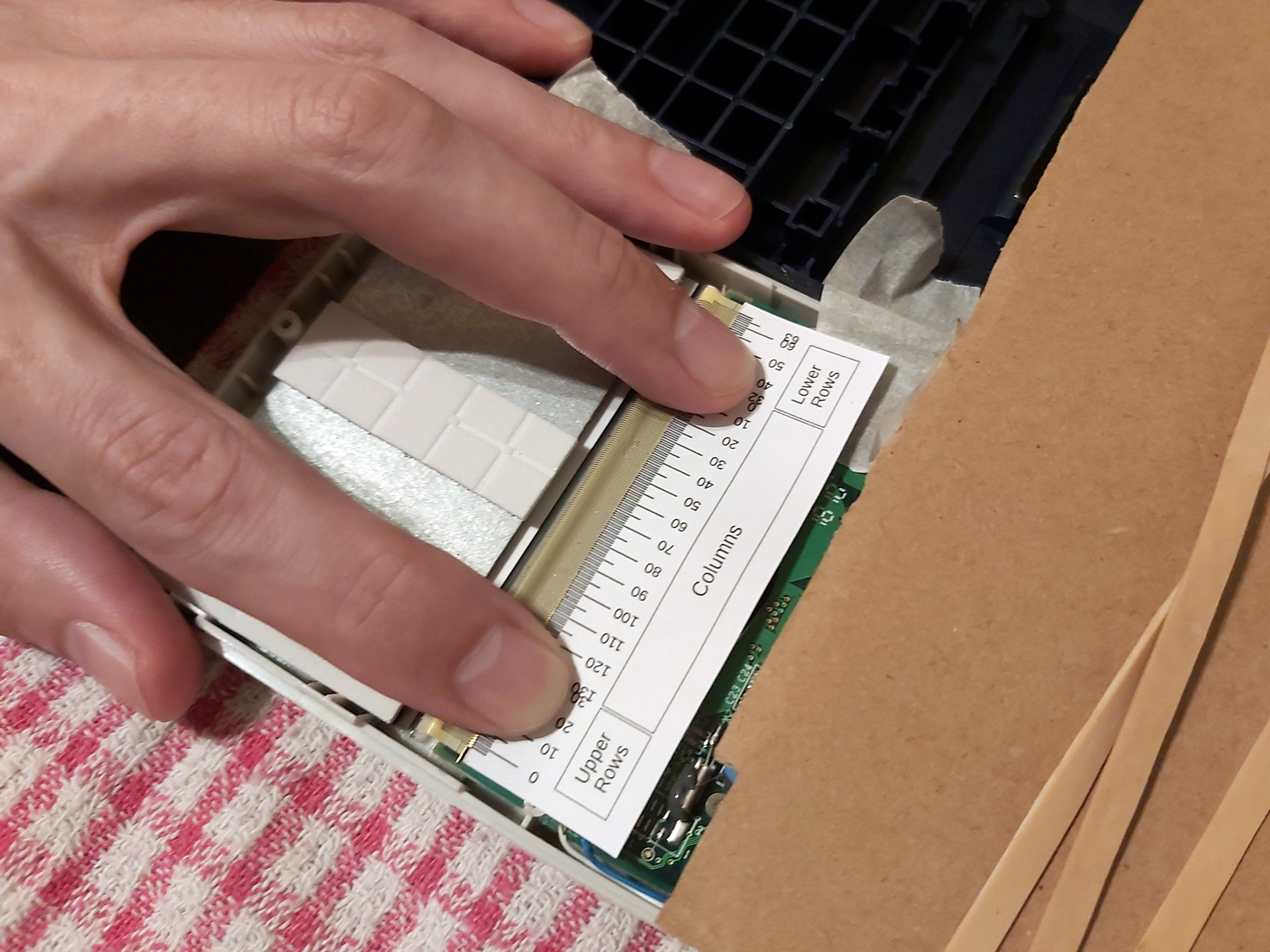
Note that the "Lower Rows" are – I think – incorrectly ordered in this photo.
The flex cable can be broken down into three areas. The large central area corresponds to the columns, though as we are working on the back of the LCD the column numbers are reversed (and so run from right to left, rather than left to right). The left hand side of the flex cable corresponds to the top half of the display and the right hand side corresponds to the bottom half. I worked this out by removing the LCD from the calculator I'd previously destroyed and holding it up to a bright light to see where the traces in the glass went. Fortunately for me but unfortunately for testing purposes the LCDs in the calculators I've repaired have only had faulty rows in the upper half of the display, which means that I initially got the order of the "lower rows" reversed – having sketched it out on some paper I think the middle row (32) will be connected on the outside of the flex cable and the bottom row (63) will be on the inside, nearest the "columns" section, as otherwise the traces would have to cross over each other. I have updated the PDF and ODG, but that explains the error in the above photo, and until I find a calculator with a fault in the lower half I won't be able to double check.
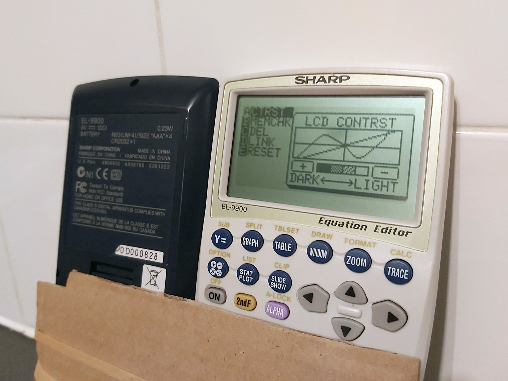
All the rows and columns are back, but sadly I can't do much about the LCD "bruise" below the C in CONTRST.
I was able to use the guides to successfully repair the two recently-acquired calculators by only heating the affected parts of the flex cable. I also used a lower temperature on the soldering iron than before (220°C) and that seemed to be enough to stick the cable back down – I'd only hold it against the flex cable for a short amount of time, lightly running it down the cable in the direction of the traces and then holding the flex against the PCB firmly with a finger as it cooled.
In case you found this post because you also have a faulty EL-9900 calculator and are looking for some repair tips, here's what springs to mind:
- The calculator has five main screws on the back as well as one smaller one inside the battery compartment under the third cell from the left. You do not need to remove the screw on the memory battery backup door.
- The case has four clips on the sides holding the two halves together. I find it easiest to unclip the first two from the top (the guide for the hard case widens at the top, giving you plenty of room to insert your fingers to pull, with the two clips being towards the bottom of the LCD). Squeezing the white front half of the calculator whilst continuing to pull will release the lower two clips. Do not fully separate the two halves yet, you just want to release the clips.
- There are four very thin wires between the rear half of the case (containing the battery compartment) and the front half of the case (containing the main PCB). The two halves of the case can be opened like a book with the opening on the right hand side when looking at the front of the calculator.
- As the battery compartment is connected with wires (rather than, say, spring contacts to the main PCB) the calculator can be operated when open. However, a switch on the main PCB (normally pressed by a stud on the battery compartment door) prevents this from happening – a piece of tape will hold this down and let you switch the calculator on.
- The connections for the thin wires between the battery compartment and main PCB are extremely fragile, so if you keep opening and closing the calculator when working on it these will likely break and need to be resoldered. To avoid this, I recommend only opening the calculator up once, then using some tape to join the two halves of the calculator together at the "hinge" and using two pieces of cardboard and an elastic band to hold everything together as this will let you flip the calculator over between working on the flex cable and checking the LCD without stressing those thin wires. The keyboard should also be popped out to prevent the cardboard from holding down the keys (the fixed keys above the removable keyboard are more than sufficient to test the calculator when working on it).
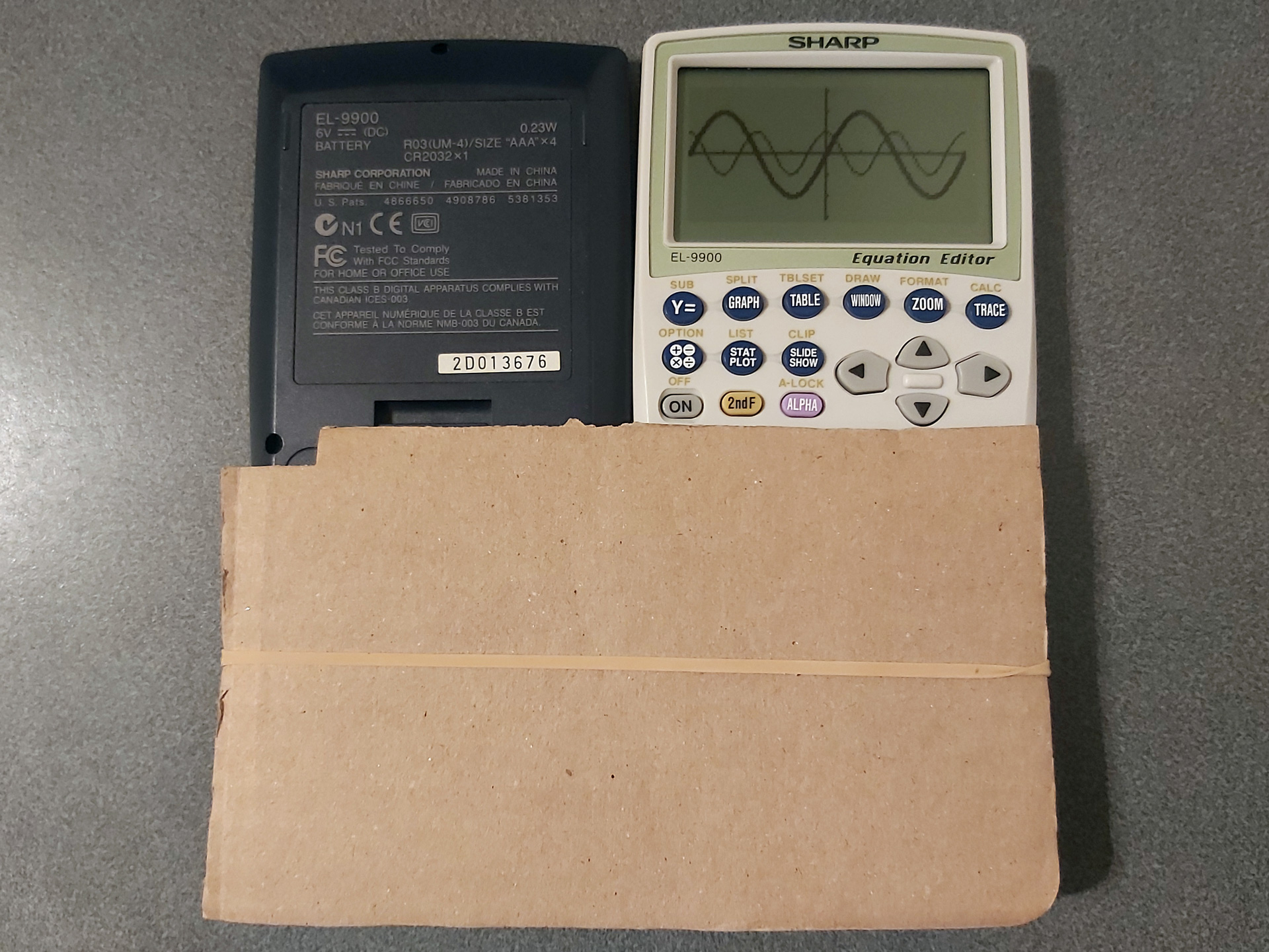
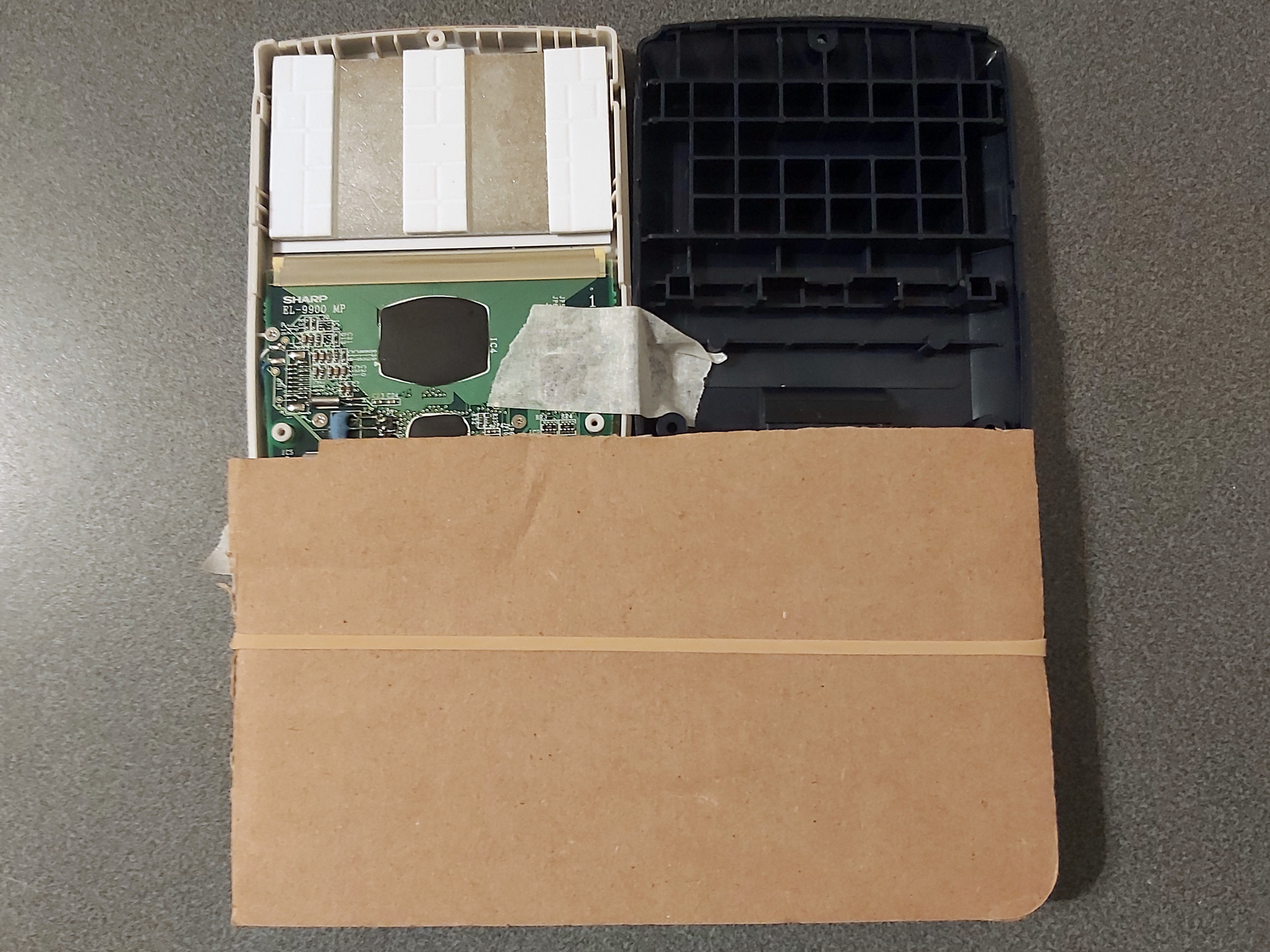
- Only poke the soldering iron near the part of the flex cable that's stuck to the board. The soldering iron will very easily melt a hole in the flex cable if you touch it in the unsupported gap between the PCB and the LCD glass.
- Once you've repaired any known faulty rows or columns, test the calculator over a period of a few hours before closing it back up in case the fixes don't hold or any new faults appear after disturbing the flex cable. Keep a list of rows or columns you've repaired to see whether the issue is one you've repaired before or whether it really is a new fault.
- When closing the calculator back up, it's much easier to do this without the keyboard installed due to the sprung pin that normally tries to push the keyboard out. I also find it easier to put the spring and pin in the back half of the calculator and to lower the front half on top of it (threading the pin through the small hole in the front) rather than balancing the pin with the spring on top of it in the front half and lowering the back half on top of that.
Here again is the link to the printable repair guide (LibreOffice Draw file), and maybe it'll help you if you have a faulty EL-9900. It's certainly helped me – good luck!
Various calculator-related updates: BBC BASIC, Vinegar, Telnet 83, Brass and Latenite
Sunday, 14th June 2026
My original TI-83 Plus feels like it's on its last legs. I suspect there's some issue with the flash memory, and I've already had to wipe its certificate page using the BootExec utility that exploits a buffer overflow in the link routines to get an operating system back on it. Even though it's working for now, I'm somewhat wary of installing flash applications on it.
Recently, however, someone contacted me to let me know that there was a bug in the TI-83 Plus version of Richard Russell's BBC BASIC that I'd put together a few years ago. It turns out that on more recently-manufactured TI-84 Plus calculators uses a new LCD driver which modifies the data pointer when reading back the status register. The BBC BASIC host interface I'd put together polls the busy flag in this status register, and so the display was corrupting on these new calculators as writes to the LCD memory were not going to the correct address.
It was a reasonably easy fix (replacing my own LCD busy test with a call to the one provided by the calculator's operating system), but not one I could test myself as I don't own a TI-84 Plus. I also wanted to check that there weren't any regressions with the fix, but I didn't want to risk damaging my TI-83 Plus further by reinstalling the flash application on it.
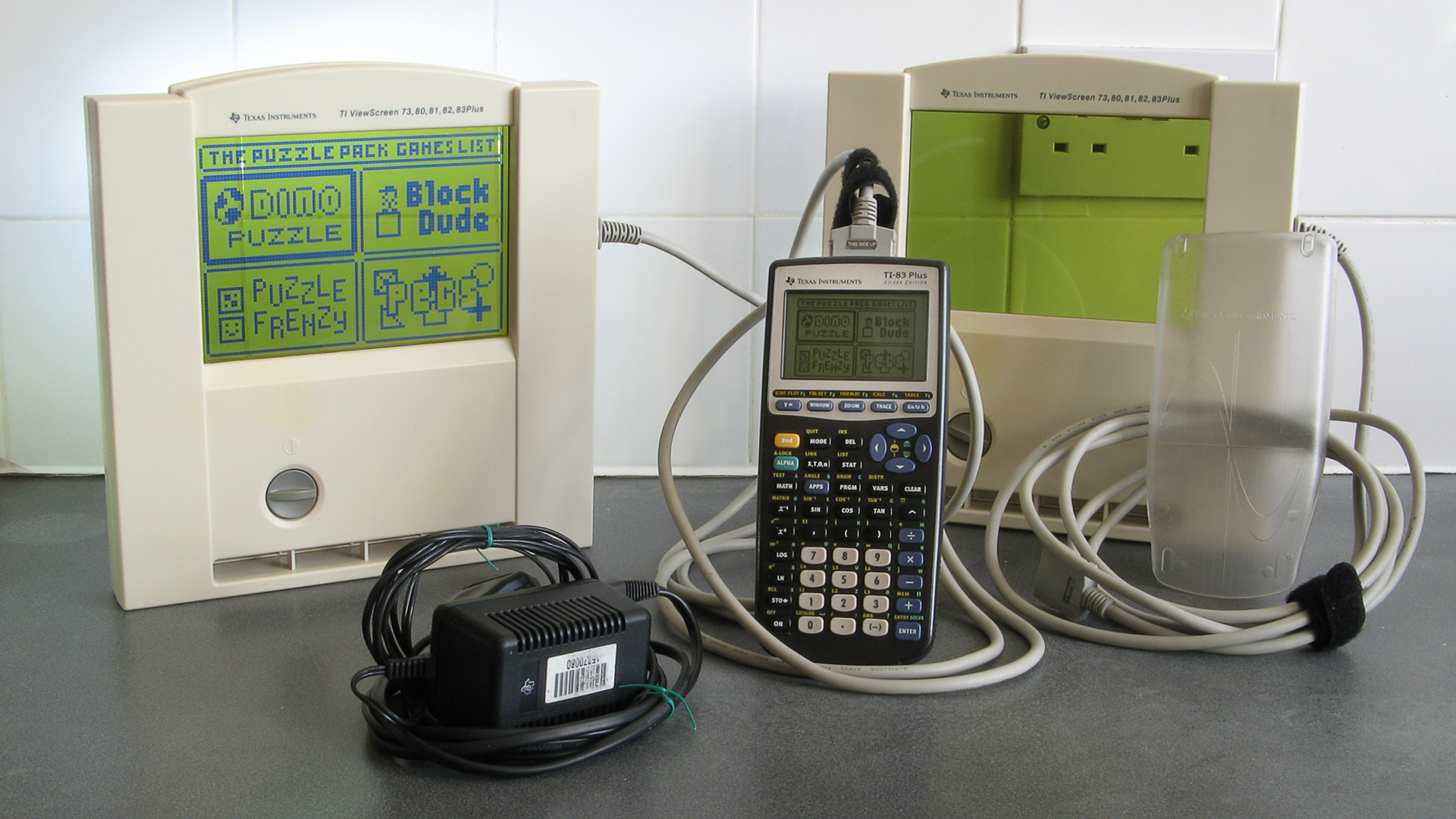
I did find the above TI-83 Plus Silver Edition calculator on eBay, though, for a good price – and it's the ViewScreen model! This has a special socket on the back of the calculator that lets you plug in a large external LCD (it came with two of them) which is designed to be used on an overhead projector so a teacher can demonstrate using the calculator to their students. I'd previously experimented with a project that displays the calculator's screen on a TV, but that captures a screenshot over the calculator's link port so is slow, requires a button to be pressed to update the image and only works in situations where the OS is idly waiting for a keypress. The ViewScreen taps into a buffered copy of the signals sent to the calculator's LCD driver, so will automatically and immediately show a copy of what's on the calculator's own screen.
Now that I had a TI-83 Plus Silver Edition I installed BBC BASIC on it, saw that the LCD fix had worked and not broken anything else, but also encountered a few other bugs that I'd not noticed before which I've also fixed:
- Pressing non-printable keys (e.g. cursor keys) in INKEY no longer slows CPU down to 6MHz until the app is restarted.
- Pressing Clear in INPUT statements now clears the whole input line instead of inserting a CHR$27 into the line.
- The On key only triggers escape when pressed. On the Silver Edition it was triggering when released as well.
These updates have been uploaded to the project page on this site, the GitHub page and ticalc.org.
Now that I had a shiny new calculator, I thought I'd try installing some other old programs on it to see how well they worked. One of these was Vinegar, a CHIP-8 and SCHIP 'emulator'/interpreter. I soon found that this also had an LCD bug on the TI-83 Plus Silver Edition, as enabling the "96x64 SCHIP mode" (which scales the 128×64 native resolution of SCHIP games down to the calculator's 96×64 display instead of cropping it) would erroneously switch the LCD driver into "6 bits per column" mode after a few seconds of play instead of the intended "8 bits per column" mode, corrupting the display.

How the options menu should appear (left) versus how it appears on the Silver Edition (right) due to a bug.
This project had some very old code and had never been checked into source control so I set it up on GitHub, combined the copy of the source code I had on my local machine with the source code that was publicly available for download and fixed the LCD bug. I also found and fixed a memory leak bug that occurred if no CHIP-8/SCHIP programs ("ROMs") were installed on the calculator and added a couple of keyboard shortcuts to control the display. These changes are available in release 1.2 on the main project page, the GitHub page and ticalc.org.
The next bug I spotted was in Telnet 83. I didn't originally write this particular program, but it is included as part of the TIWiFiModem project where I've already made some bug fixes and improvements. When trying to use it to set up my TIWiFiModem with my new wireless access point I discovered that I couldn't type in the password as some of the keys were not being mapped correctly. I'd previously corrected other key mapping bugs in this program but must have missed a couple, so these are now fixed. There isn't an official release for this project but the compiled .8xp is checked directly into the repository so can be downloaded from there.
I use my old Brass assembler to build the Telnet 83 project. Some other people do still use this from time to time and so I decided it would be best for the community if the source code was available, no matter how embarassingly poorly-written it was. To this end I set up a GitHub repository a few years ago, but as the code had never been checked into source control before then there was no accompanying history. I did have a few old backups and so imported them into the repository in date order, but as these backups were taken around 20 years ago with no notes as to what I was thinking at the time it's all a bit of a mess!
As this is not intended to be an actively-developed project I don't plan to make too many changes to it, but I have fixed a couple of bugs along the way. Notably, operator precedence is handled more correctly now (operators with the same precedence, such as * and /, are now evaluated from left to right whereas previously * had higher precedence than /). When working on Telnet 83 I also found that if data overlaps in the output binary the reported address range was incorrect and also poorly-formatted, and this has now been fixed too:
Brass Z80 Assembler 1.0.5.4 - Ben Ryves 2005-2023 ------------------------------------------------- Assembling... Pass 1 complete. (310ms). Pass 2 complete. (84ms). Writing output file... Warning: Data overlap between$14930-$14930. ← Now shows the correct value '$AB9D' Errors: 0, Warnings: 1. Done!
String literals were also handled very oddly, and I've slightly improved this and added extremely rudimentary expression parsing on string, so #include "page" + pagenum + ".asm" now works as you might expect. I've filled in some of the missing gaps in the documentation, too; updates can be downloaded from the Brass page on this site or the GitHub repository.
An even more ancient development tool that I put together was Latenite, an IDE designed to be used for Z80 development. I hadn't used this myself in years (preferring to use Visual Studio Code as an editor and the Brass 3 Project Builder to build the code and launch a debugger) but Vinegar was set up to use this (including a project file, build scripts and debug scripts) so I thought I'd give it a go. Unfortunately, it really didn't work – the files I had on my local development copy didn't match what was in the publicly released zip files, and neither worked with what Vinegar was expecting.
Again, I set up a GitHub repository for the project and tried to piece together a working code base using the files I had locally, the files that had been publicly released and what I could remember of what had gone on twenty years before.
The solution contained a series of projects for tools (an 8xp "linker", a TASM error processor and a WLA-DX error processor) that aren't included in later releases of the software. I suspect these are remnants of the project from before Brass became the bundled assembler. I have added the Brass repository as a submodule to the project so that it can be built alongside Latenite, and that will hopefully help keep things in sync.
A notable sticking point was a conflict in the PindurTI-based debugging system. There appear to be two different versions, with different debug scripts and executable names. The older "PTIDebugger" was a project in the Latenite solution I had locally, and is what the Vinegar project was looking for, however the bundled project template for TI-83 (Plus) development uses a new executable called "PindurTI Debugger" and set of debug scripts with incompatible file names and I had no record of its source code anywhere.
Fortunately, the old Latenite interface for this debugger is still present in the PindurTI debugger that's part of the Brass 3 repository, so I suspect this was originally developed for Latenite before being incorporated in the Brass 3 project. I can't currently use this as a submodule of the Latenite project as it has a dependency on Brass 3 (and I don't want to have to bundle the whole of Brass 3 in the same project, as it's not relevant) so I just copied the code over and removed the Brass 3 bits.
PindurTI is an emulator developed by the legendary Patai "cobb" Gergely, not that you'd know it from the lack of attribution in Latenite or my other development tools. Similarly, calculator shells were bundled directly for debugging purposes without mentioning their authors or including their documentation, just a raw binary. For the most part image resources used in the IDE were nicked directly from Windows XP or Visual Studio, too. This is all very naughty! Whilst I don't really intend to pick up development on Latenite again, beyond fixing some of the more obvious bugs, I would at least like to try to remedy this. I've already replaced the image resources with new icons and now provide links to the calculator shell documentation from within the IDE. There's still a way to go before I'm happy with this, though.
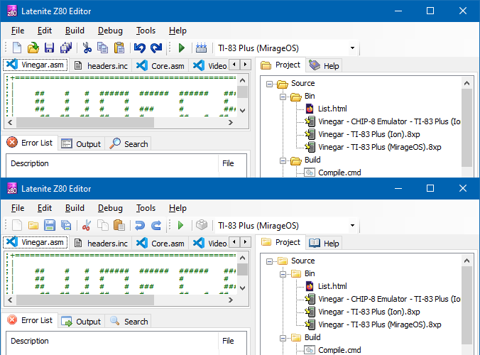
A comparison of the old icons (top) compared to the new icons (bottom).
I don't expect anyone to be still using this development tool, but in case there are old projects out there that were assembled using it then in the interest of making sure they can still be built in the future I think it's worth making sure the source code is available.
All of this relates to calculator programming and the place where I used to share all of this was the MaxCoderz forum. This has had very little traffic for the past few years, but if you were one of the few people looking for it you might have noticed that until very recently it was unavailable. This was due to bots very aggressively scraping the content, causing phpBB to insert millions of rows onto the session table on the database – this one site that had virtually zero legitimate traffic ended up slowing down the entire server to a crawl a few times per day, and though I did at first selectively block the bots it ended up being a very tedious game of Wack-a-Mole and so I ended up taking down the whole forum.
Nobody had complained about the site being down, but in the interest of keeping sites online for historical interest I have restored the site and it's now protected with CloudFlare. This is not something I'm too happy about doing, but I'd rather have a site accessible via CloudFlare than not accessible at all.
One thing I have noticed is that this site is very poorly-equipped for distributing information about updates, with so many projects being scattered across different (and poorly-maintained) sections of the site. I am currently working on overhauling this site and shifting it onto a new platform, but one of the key requirements is to not break any of the existing links or content so it'll take a bit more work to get it ready.
Subscribe to an RSS feed that only contains items with the Graphing Calculator tag.