Loading BASIC programs from cassette tape to the Sega Master System
Monday, 16th August 2021
After I posted about the pattern filling modes on Twitter I was alerted to the BBC Micro Bot website which hosts a gallery of programs that produce impressive graphical output from very short BASIC programs (short enough to fit in a Tweet!)
I tried a few of them out but unfortunately ran into problems with a lot of them that use various tricks to reduce the original program text length by embedding non-ASCII characters directly into the body of the program. My usual approach to prepare programs was either to copy and paste them into an emulator (my emulator strips out non-ASCII characters on pasting, as these can't be mapped to keystrokes) or to save them to a file and transfer that serially, and my own editor's tokeniser and BBC BASIC for Windows both had a habit of mangling the non-ASCII characters.
The BBC Micro Bot website does not provide a way to download the BASIC programs directly but does provide a share link that allows you to export a disk image or play back the program from a virtual tape cassette. I don't have a a disk drive attached to my Master System, but the tape option seemed promising...
The basic cassette tape interface
My initial approach to loading programs into BASIC from external storage was to connect my Cambridge Z88 computer running PC Link 2 or EazyLink to the Master System with an RS-232 serial cable. This works well for me, but isn't very practical for others who might not already own a Z88, and I do want this to be an easy project for people to replicate!
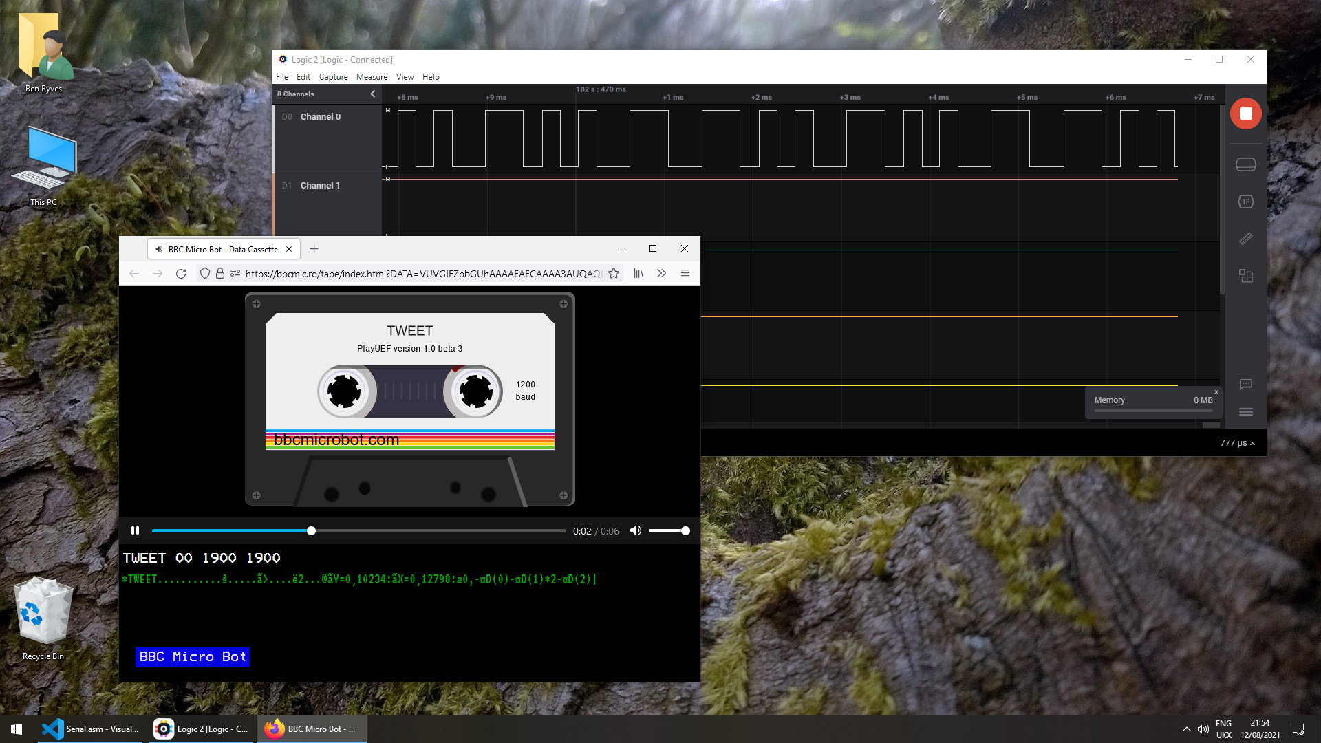
Being able to load from tape would significantly lower the barrier to entry, if the cassette tape interface circuit can be constructed easily. You wouldn't even need an actual tape player; the drive belts have gone in mine (I tried to make a test recording on mine and it just unspooled the tape into the bowels of the machine) so for the time being I've been testing loading from PlayUEF, the web-based UEF player that's also found on the BBC Micro Bot website. This can be run from a browser and it works well on my mobile phone and makes loading programs from a web link an absolute doddle. Perfect!
The challenge, then, is how to get that audio data into the Master System in the first place and whether it's got enough grunt to be able to decode it in software. Using the same tape format as the BBC Micro seemed like it would be a good choice so I read this article on the Acorn cassette format on BeebWiki. The highest frequency audio signal is a sine wave at 2400Hz. As we'll need to handle both halves of each cycle we'll need to sample the signal at least 4800 times per second. As the Master System has a CPU clock of around 3.58MHz, that gives us 3.58×10⁶/4800≈756 CPU cycles for each half of the cycle which should be more than sufficient.
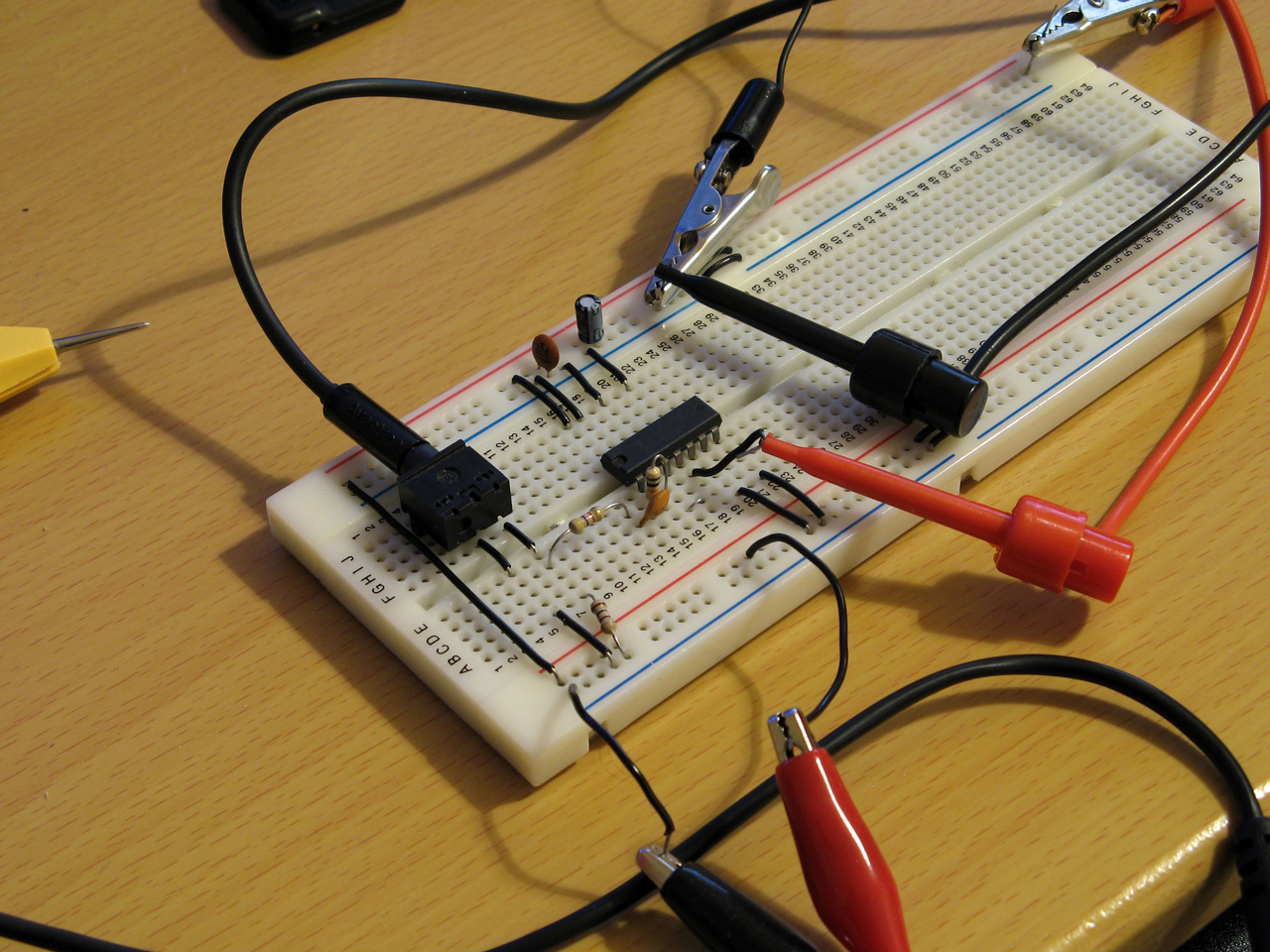
We still need to get the audio signal into the Master System somehow! I did a bit of digging online and couldn't find too much information about suitable electrical interfaces. My best lead was the circuit diagram for the BBC Micro's tape interface, however that requires several op-amps and I only have a single LM741 in my parts bin, which isn't going to do a very good job on a single 5V supply. In the short term I've used the circuit above which is a slightly modified version of this common circuit used to convert S/PDIF signals to TTL levels using an unbuffered hex inverter as an amplifier. It's not the most stable circuit and has a habit of oscillating when not fed an input signal but the +5V pullup on the output from the console inhibits this (putting a pull-up or pull-down on any of the inputs changes the mark:space ratio of the pulses). That a load on the output affects what's happening on the input is definitely not a good indication of a properly-functioning circuit, but it'll have to do for now.
I don't know how well it'll respond to a real tape cassette player, but the signal from my PC's sound card or my mobile phone produces very clean square pulses so it should be enough to start experimenting with until I can come up with more stable design.
Decoding the tape signal in software
To decode the signal we'll need to know whether the tape is outputting silence, a 1200Hz tone or a 2400Hz tone. I'm handling this with a simple routine that samples the current level of the input, then loops around waiting for the input level to change state, counting the number of times it takes to go around the loop before the transition. If the counter overflows before the state changes then it's assumed that the tape is outputting silence, but if the state changes before that we can check the value the counter reached to see if it got to a small value (a high frequency signal from the tape) or a large value (a low frequency signal from the tape).
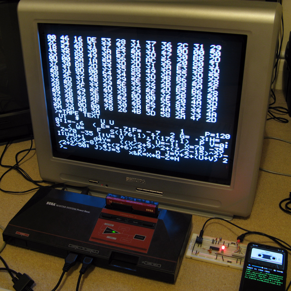
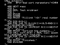
To determine a suitable value for the thresholds I wrote a test program that simply called this routine in a loop 256 times, storing its results in memory, before dumping the results to the screen once all 256 values had been found. By playing a section of the tape in the middle of a data block (so there would be a good mixture of 1200Hz and 2400Hz tones) I got the rather pleasing result that 1200Hz tones appeared to make the counter reach $20 (32) and 1200Hz tones made the counter reach $10 (16), so I put the threshold value between them at 24 as an initial test.
Once we know the frequency of the tape signal at a particular point we can use this to determine the current bit – a "0" bit is a complete 1200Hz cycle (so we'd see two instances of the counter reaching >16) and a "1" bit is two compete 2400Hz cycles (so we'd see four instances of the counter <16). Knowing the bit on its own is not very useful, though, so I added byte decoding which waits for a start bit (0), receives and stores 8 data bits, then checks for a stop bit (1). I could then dump this data to the screen:
At this point the data isn't completely correctly decoded, but it always produces the same results on every run-through which to my mind was a good sign. The text displayed at the bottom of the screen shows some recognisable fragments of the original BASIC program (as the program is tokenised the keywords are missing). The main problem I was having was down to synchronisation; as the article on BeebWiki states "an odd number of 2400Hz cycles can and does occur" and these occasional cycles were throwing me out of sync. The fix was to add an extra check when handling 2400Hz; even though four 2400Hz half-waves are expected, if a 1200Hz half-wave is detected instead it's assumed that we've gone out of sync and the bit should be decoded as a complete 1200Hz pulse instead. After making this change more recognisable text started coming through, so I was able to move on to decoding the data blocks.
Decoding data blocks on tape
Files on tape are broken up into multiple data blocks, each with a header describing the block (e.g. file name, block number, data length) followed by a variable amount of data (up to 256 bytes) containing the data itself. To load a file from tape each incoming block has to be handled. If the block number is 0 then that's the start of the file, so the filename is checked. If this matches the supplied filename (or the supplied filename was the empty string "") then the loader switches from "Searching" to "Loading" mode and the data we just received is stored in memory. From that point on each incoming block is appended, as long as the block name and number match what we expect (i.e. the same filename as before but the block number should be the previous block number + 1). This continues until the "end of file" block flag is set. A CRC-16 of the received data is also checked after each block to ensure that the data has been received successfully. If there are any errors (the block name/number doesn't match what was expected, or the CRC-16 check fails) then an error message is printed and you can rewind the tape a bit to try receiving the block again.
This doesn't sound too complicated, but I've not had too much luck implementing this successfully. My code is currently a bit of a mess and doesn't properly maintain the "Loading" or "Searching" states which means that if an error occurs at any point then it can get a bit confused trying to resolve it (to the point where it's easier to just abort the load and start again from the beginning). However, the tape block issues are not the only problem...
Conflicting BASIC program formats
The programs I'm trying to load are designed for the BBC Micro, where programs are stored in the Acorn or "Wilson" (after Sophie Wilson) format. However, BBC BASIC (Z80) was written by Richard Russell and therefore uses the "Russell" format. Both have a lot in common, fortunately but the way each line is stored in memory differs (this is covered in more detail in the "Program format" article on BeebWiki). Fortunately the formats are similar enough that it's possible to convert them reasonably trivially in-memory.
My initial plan was to leave the loaded program as it is, and to provide a star command (e.g. *FCONVERT, named after the FCONVERT.BBC program) to convert from the "Wilson" format to the "Russell" format. Unfortunately, after loading the file BBC BASIC (Z80) checks the program and applies its own fixes to it, notably writing the appropriate terminator on the end of the program. As far as I can tell it does this by following the program along, line by line, until it finds what it believes is the end. In the "Russell" format the first byte of the line is its length, and in the "Wilson" format it's a carriage return (value 13). What I think this means is that BBC BASIC (Z80) thinks that the second line of an Acorn program should occur 13 bytes in, and as this isn't likely to be the case it ends up writing its terminator 13 bytes in to end the first line. This prevents me from fixing loaded programs after the fact, as they've already had part of their contents overwritten.
Instead, I've added a check to the program after I've loaded it but before I've returned control to BBC BASIC. If I am able to read the program from start to end in "Wilson" format then I apply the conversion to "Russell" format automatically. In practice this means that both file formats load correctly, but I don't particularly like the way that if you LOAD a "Wilson"-format file then SAVE it back it'll be saved as a "Russell"-format file.
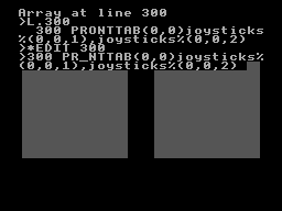
There are still some differences in the formats and the way they're tokenised but usually that can be fixed by loading the problematic lines into the line editor (*EDIT) and pressing Return without making any changes. This forces them to be retokenised and has fixed some of the issues I've run into.
Another issue is that "Wilson" format BASIC files support a line number 0, but "Russell" format ones do not; the file will be loaded and can be run, but if you try to LIST it then it'll stop when it reaches line 0 (which is usually the first one!) so programs appear to be empty. This is not something I think can (or indeed should) be fixed automatically but if necessary you can change the line number for the first line from 0 to 1 with ?(PAGE+1)=1 so there is at least one solution.
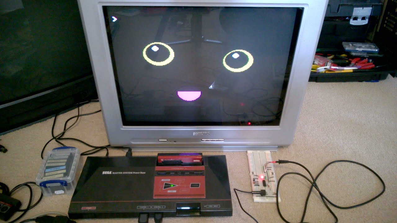
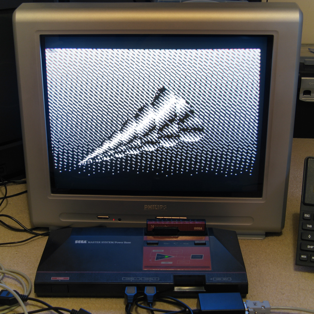
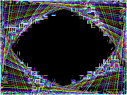
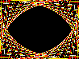
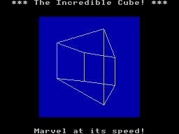
The video above shows a couple of programs being loaded from the BBC Micro Bot website onto the Master System. Even with the terrible audio to digital interface it gets the job done! The 7905=7905 messages at the end of each block during loading show the CRC-16 calculated for the received data followed by the expected CRC-16, as they match it indicates the data is getting through successfully.
Emulating the tape interface
As alluded to above my current loading system works well enough when everything is OK but it gets a bit confused when there's a fault. I never really planned out how to handle this and the code's a bit of a spaghetti mess in places so I drew out a flowchart of a more robust loader, which itself is also a bit of a mess but hopefully one that will make loading tapes more user-friendly and robust.
Unfortunately, doing any work on this interface has been very tedious as every time I make a change I need to try it on real hardware – I don't know of any Master System emulators that include tape support! I've been using my own Cogwheel emulator throughout which is itself not a very good emulator (there are no proper debugging tools, for example) but I can at least bolt on weird features I need like PS/2 keyboard emulation, so I thought it would be a good use of my time to add tape interface emulation. I started by writing a UEF (Unified Emulator Format) parser that could turn a UEF image file into a 4800 baud bitstream that could be fed into the Master System's controller port. For some reason my files end up being slightly different lengths to the sound files generated by PlayUEF – nothing major, but a handful of seconds over the length of a roughly 7 minute file. I tried loading the generated bitstream as a 4800Hz sample rate file into Audacity and it didn't quite line up with the audio file generated by PlayUEF either, but after poring over the specifications for the UEF format I was unable to figure out where the discrepancy lay.
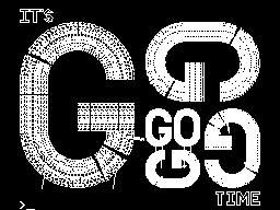
Undeterred I pressed ahead and added this simple cassette player to the emulator, which happily seems to work well in spite of the reported timing differences:
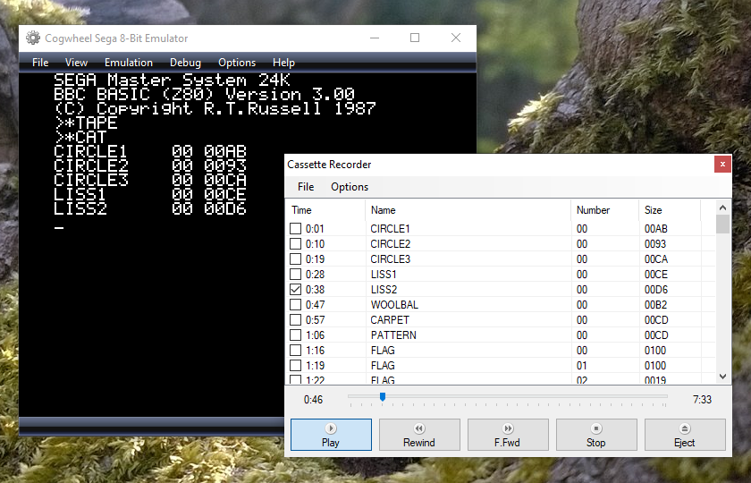
One thing that's notable there is that the program CIRCLE2 appears in the catalogue on-screen. When I first added the cassette interface emulation it was missing, but it would not be detected on real hardware either, which made me quite happy! Being able to more rapidly make and test changes to the tape loader code I was able to experiment and found that the tape loader seemed to miss the synchronisation byte ($2A) sent at the start of block headers on the CIRCLE2 program. This seemed to be due to going out of sync with the bit stream in the period between detecting the carrier tone and the first start bit, so I changed the code to demand exactly two 1200Hz half-waves as the start bit rather than using my more lax code that decodes the contents of the main bit stream that allows for extra 2400Hz pulses. This ensures that the start bit is always properly synchronised, and after making this change CIRCLE2 appeared in the catalogue as it should. I then reflashed the ROM chip on the cartridge and tried on real hardware, and that now picks up CIRCLE2. Being able to fix a problem that appears on hardware by replicating and resolving the same issue in software emulation justifies the few hours I spent adding the cassette tape emulation!
Unfortunately, I'm down to under a hundred bytes of free program space on the 32KB ROM I've been developing with, and I still have a lot of features I'd like to add (including the more resilient tape loader). I've been trying to put this moment off as long as possible as I'm going to have to use bank switching to map in additional memory banks, and that means a lot of difficult decisions about what code lives on which ROM pages to minimise the amount of switching that's required. Conventionally slot 2 is used as the slot to map different banks into but at the moment that's where I've mapped in the cartridge RAM to extend BASIC's memory. On the plus side very little of my code needs direct access to BASIC's memory (I mostly use my own data storage or the stack which lives at the top end of memory, far above slot 2) so this would seem like a good fit but I currently allocate storage space in BASIC's free memory for some operations (e.g. as temporary space when copying data around the screen during scrolling operations) so I'll need to change that code to use memory allocated elsewhere. It's not the most glamourous part of the project, but it'll need to be done if I am to add all the features I'd like.
Patterned fill modes for the Master System version of BBC BASIC
Tuesday, 10th August 2021
One of the features I was quite happy with in the TI-83 Plus version of BBC BASIC was the dithered fills used to provide some semblance of different colours. Sixteen different patterns were provided between black and white:

As well as baking in the sixteen different dithered patterns I added a command that let you use your own pattern tile in a very hacky method (you'd allocate the memory for the pattern via DIM and then pass the address of that memory to GCOLPAT – the extra "PAT" statement after GCOL is what did the trick).
What I didn't realise at the time is that the BBC Micro also had support for patterned fills via its Graphics Extension ROM and a much more natural way to interact with it – GCOL 16,0, GCOL 32,0, GCOL 48,0 and GCOL 64,0 let you select one of four pattern slots, and you can redefine the patterns with VDU 23,2,… to VDU 23,5,… followed by 8 bytes of pattern data, similar to how user-defined characters are already programmed.
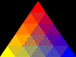
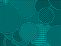
Armed with the Graphics Extension ROM's user manual and sample programs I went ahead and implemented these patterned fills in my four- and sixteen-colour modes. Here's the output of the "shades" program, which runs in a four-colour mode and generates dithered fill patterns for the triangle to simulate different shades:
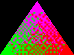
Depending on the number of colours of the screen mode you're currently in the 8×8 bitmap used as a fill pattern is interpreted differently; in the 16-colour mode it represents a 2×8 pattern that is repeated four times horizontally, in 4-colour mode it represents a 4×8 pattern that is repeated twice and in 2-colour modes it's a complete 8×8 pattern with no repetition. I like the idea of these 8×8 patterns so added a new two-colour video mode, mostly based on the existing four-colour mode but with the palette limited to two colours and the revised rules on interpreting fill patterns. This produces results like the following from the "pattern" demo program:

I've also implemented VDU 23,11,… (it resets the four patterns to their initial values) and VDU 23,12,… to VDU 23,15,… – these are helper commands that let you populate a fill pattern from a 2×4 list of colour values that is then repeated across the specified pattern number regardless of the current screen mode and without you needing to perform the bitwise arithmetic to pack the different colour values into memory properly. You may have also noticed that the four patterns are spaced sixteen GCOL numbers apart from each other (16, 32, 48, 64) – this is because you can use these pattern fills in conjuction with the logical plotting modes, e.g. GCOL 16+1,0 will OR the pattern over the existing screen contents.
These pattern fills apply to all graphics operations, so if I break out of the shaded triangle program above when it's settled on a particularly garish palette and switch to outputting text as graphics with VDU 5 I get results like the above. I'm not sure how practical or useful that would be but it does at least show how flexible the graphics plotting system is.
Better plotting modes, text anywhere on the screen and double-height characters for Sega Master System BBC BASIC
Monday, 9th August 2021
I've made quite a few changes to the way colours and plotting modes are handled in the Sega Master System version of BBC BASIC; previously this was handled on a per-graphics-mode driver basis, but this resulted in a lot of duplicated code and some inconsistencies. The new code is a bit more straightforward but also adds quite a few new features, most obviously different plotting modes:
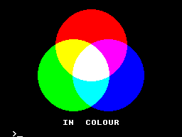
Plotting with the OR mode
The above screenshot shows the result of filling three circles with the OR plotting mode. The red circle is colour 9, the blue one is colour 10 and the green one is colour 12. Where the colours overlap they are ORed together when drawing, so for example red OR blue is 9 OR 10 which is 11, the colour code for magenta, hence the colour between the two is magenta. Where all three colours mix, that's 9 OR 10 OR 12 which is 15, the colour code for white.
It's the logical colours (the palette indices) that are combined by these plotting operations, rather than the RGB values, it just happens that the stock palette lines up neatly with the RGB values!
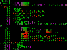
Another addition I've made is support for VDU 5. In normal operation, text sent to the display is displayed at the text cursor position. In VDU 5 mode the text is instead drawn at the graphics cursor position, which allows text to be drawn anywhere on the screen, outside the confines of its usual grid. It also takes into account the graphics plotting modes mentioned above and so you can blend text with other graphics operations. Here's an example:
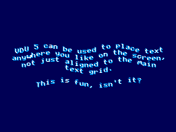
The somewhat blurry text has been drawn in two passes slightly offset from one another, once with colour 1 and again with colour 2, ORed together so that where the text overlaps you get colour 3, which is white. The program for this is as follows:
 10 REM Draw wavy text in a watery style.
 20 MODE 2
 30 REM Set up a suitably watery palette.
 40 COLOUR 0,0,0,64
 50 COLOUR 1,0,64,128
 60 COLOUR 2,0,128,255
 70 COLOUR 3,255,255,255
 80 REM Draw text at the graphics cursor position.
 90 VDU 5
100 REM How many lines of text will we draw?
110 RESTORE
120 L%=-1
130 REPEAT READ L$
140   L%=L%+1
150 UNTIL L$=""
160 REM Draw in two passes, slightly offset, in OR mode for a blurry effect
170 FOR C%=1 TO 2
180   GCOL 1,C%
190   RESTORE
200   Y%=(960+L%*50)/2
210   REPEAT READ L$
220     IF LEN(L$)>0 AND L$<>"-" PROCWAVES(L$, C%*4, Y%-C%*4)
230     Y%=Y%-50
240   UNTIL L$=""
250 NEXT C%
260 REM Restore normal text operation.
270 VDU 4
280 REM Wait for a key then exit.
290 REPEAT UNTIL INKEY(0)=TRUE
300 REPEAT UNTIL INKEY(0)<>TRUE
310 END
320 REM Draw some wavy text at X%,Y%
330 DEFPROCWAVES(TEXT$,X%,Y%)
340 LOCAL I%
350 X%=X%+(1280-(LEN(TEXT$))*35)/2
360 FOR I%=1 TO LEN(TEXT$)
370   MOVE X%,Y%+20*SIN(X%/80+Y%/160)
380   X%=X%+35
390   PRINT MID$(TEXT$,I%,1);
400 NEXT I%
410 ENDPROC
420 REM Text strings to display.
430 DATA "VDU 5 can be used to place text"
440 DATA "anywhere you like on the screen,"
450 DATA "not just aligned to the main"
460 DATA "text grid."
470 DATA "-"
480 DATA "This is fun, isn't it?"
490 DATA
When you're finished you can use VDU 4 to return to the normal text mode. In the video modes where I've had enough free VRAM to spare for it I've also added support for user-defined characters. You can send 23, then a character number, then eight bytes of pixel data for the 8×8 character bitmap to the VDU and then use that data for subsequent text operations (the characters from &80..&FF can be redefined). These user-defined characters can also be used as 8×8 sprites when combined with VDU 5.
I'm having quite a lot of fun writing my own test programs but it's also been useful to be able to run existing software as a test. I've tried to improve my sound handling and it now sounds a bit more faithful to the BBC Micro (though the Master System is a slower machine, so it can't quite keep up with more adventurous pieces of music).
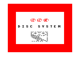
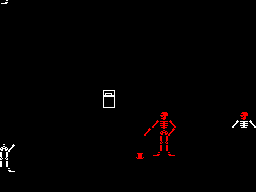
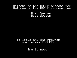
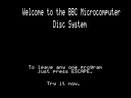
The BBC Disc System "Welcome" screen and the Bones demo
With the new graphics plotting modes and VDU 5 support the BBC Disc System "Welcome" program runs, for example, though it looks a bit rough around the edges due to mismatches in the video modes. Bones also runs, however the mismatch is even more severe here and half way through the skeleton turns red as it's running in the four-colour video mode and COLOUR 1 is mapped to red, not the white in the monochrome mode the demo is expecting. The misalignment comes from differences in the number of rows and columns of text that are available; the demo mixes graphics commands (which are mapped reasonably closely to the BBC Micro's screen) and text; if the demo expects the screen to be 40 columns wide and the best I can offer with this hardware is 32 columns, it won't line up! Of course, the BASIC program can be tweaked to get it working properly, but it's fun to see just how close it gets without any tweaking...
One recurring issue, however, is with programs that expect to be able to use Teletext features. The BBC Micro's default video mode used a Teletext character generator, which allows for bright colourful text and some limited graphics support in very little memory. I had previously mapped this mode to the TMS9918A text mode, which allows for 40 characters in 24 rows, just one row short of the BBC Micro's 40×25. It's a fast mode and is good for program editing due to the large number of text characters on screen at a time (all other modes are 32×24) however it is very limited - there's no support for colour, for example, other than the global foreground and background colours.
To provide some colour support I loaded the character set into memory twice, once normally and once inverted, so via the COLOUR statements it's possible to inject some variety into this mode. The BBC Micro's Teletext MODE 7 doesn't support the COLOUR statement, it relies on embedding special control codes in character positions on the screen that affects the rendering of the rest of the text in the line – for example, a command might change the colour, or cause the rest of the line to flash. As I can't possibly support such codes, I just ignore them, and the programs run fine but look a bit bland.
The main exception to this, I've found, is the double-height text mode. You can switch this on within a line by storing the value 141 in a character cell and then off again with 140 afterwards. This will only display the top halves of the characters, so to display the bottom halves you need to output the same content on the line below. A lot of BBC Micro programs seems to take advantage of this feature, so most programs I'd tried ended up having doubled-up text like you can see in the screenshot above.
The character set I'm using is only 96 characters long (32-127) but I had avoided investigating this as I assumed I'd need to triple the number of characters - the regular-height ones, plus the top and bottom halves of the doubled characters. 96×3=288 which is more than the 256 characters we have available, so I didn't think this would fit.
However, I did think that maybe some characters shared parts - for example, the top halves of the colon and semicolon are the same, and the bottom halves of the semicolon and comma are the same, so I wrote a quick program to count how many unique patterns would be needed and found that it would only take 225 patterns in total, well within our 256 pattern budget!
I set up a new video mode based on the original TMS9918 text mode. This generates these 129 additional patterns for the double-height characters when initialised, and also checks the nametable when outputting characters to see if there's a "double height" control character in the same line to determine whether it should pick one of the stretched characters (picking a top or bottom half depending on whether there are an even or odd number of lines above it that also contain the double height control character).
This new mode does lose the inverted text, but I think the double-height text will be more useful in practice – or at least is better at making programs look less broken!
A four colour any-pixel-addressable video mode for the Master System
Wednesday, 4th August 2021
The video display processor in the Sega Master System is derived from the TMS9918A and provides a number of different screen modes. These modes are mostly character-based and generate the picture that is displayed on your TV based on two blocks of data in video RAM: the name table, which specifies which character appears in each cell on the screen and the pattern generator which contains the pixel data for each character.
TMS9918A "Text" mode
The "Text" mode is probably the most straightforward example. Only two colours can be displayed on the screen; a foreground and a background colour, both selected from a fixed palette of 15 colours. The name table is 40 cells wide and 24 tall. Each cell, or text position, is a single byte that refers to one of 256 patterns in the pattern generator, so the complete name table is 960 bytes long. Each character is displayed as 6×8 pixels but the data in the pattern generator is eight pixels wide, and each row is stored as a single byte with a set bit selecting the foreground colour and a cleared bit selecting the background colour (the two least-significant bits are ignored). Each character pattern therefore takes up 8 bytes of VRAM, or 2,048 bytes (2KB) for a complete set of 256.
The "Graphics I" mode changes the character size to be the full 8×8 pixels at the expense of the number of characters that can be displayed per line; this is reduced from 40 to 32, so the name table is now 32×24 and 768 bytes long. The pattern generator is the same size as before and you can still only display 256 unique patterns on-screen at a time, but there is at least some provision for colour. The top five bits of the character/pattern number are used as an index into a 32-byte colour table, where each colour table entry contains two four-bit values corresponding to the foreground and background colours for the pattern. This means that patterns 0-7 share the same two colours, patterns 8-15 have the next set of two colours, 16-23 after that and so on; 256 patterns, in groups of eight with a different pair of colours assigned to each of those 32 groups.
TMS9918A "Graphics II" mode
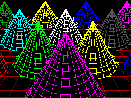
Fortunately, the TMS9918A is a revised version of the original TMS9918 which adds the much more useful "Graphics II" mode. The name table is the same as before, 32×24 cells of one byte each, and the patterns are still 8×8 pixel bitmaps. However the pattern generator table is now three times the size, storing 768 unique 8×8 patterns in 6KB. To be able to address all 768 patterns when you can only store values from 0-255 in the name table the screen is divided into three sections; the top third references the first 2KB of the pattern generator (patterns 0-255), the middle third references the second 2KB of the pattern generator (patterns 256-511) and the bottom third references the last 2KB of the pattern generator (patterns 512-767). This allows every single character position in the nametable to reference a unique pattern, and therefore have a bitmap that covers the entire screen area.
The colour table has also been significantly improved. Instead of one pair of colours for each group of eight patterns, each pattern now gets its own table of colour pairs, one per row. This doesn't allow every pixel on the screen to have its own colour, but you can at least give each 8×1 region its own pair of colours. This does lead to attribute clash when drawing; you can see this in the screenshot of the cones above, where the colour from some lines bleeds into the colour set for nearby lines if they happen to pass through the same 8×1 pixel block.
Very few Master System games use the TMS9918A video modes (F16 Fighting Falcon seems to be about the only concrete example), instead using a new video mode added specifically for the Master System. This has a number of nice new features (such as hardware scrolling and two user-definable 16-colour palettes instead of a fixed 15-colour one), but it's the name table and pattern generator that's of main interest. Instead of having a separate bitmap for the pattern and its colour table, each pattern is now a 32 byte object where each 8 pixel row is encoded as four bytes, one byte for each bit of the four-bit colour palette index. That is, if you wanted to store the top row of a pattern where the leftmost pixel was set to palette index 1, the rightmost pixel was set to palette index 15 and everything else was left as 0 it would be stored like this:
.db %10000001
.db %00000001
.db %00000001
.db %00000001
The second row would then follow with another four bytes, all the way down to the bottom row for the complete 32 byte pattern. This scheme allows you to set each pixel in every pattern to any of the sixteen colours per palette, so if you could fill the screen with such patterns then it would be possible to set any pixel on the screen to any of sixteen colours, solving the attribute clash problem. Unfortunately, to do so would take 768 patterns (32×24), and if each pattern is 32 bytes then that would take up 24KB of video RAM. The Master System only has 16KB of video RAM, which would limit you to 512 patterns, so it's not possible to fill the screen with unique patterns. In practice you can't even have 512 patterns, as you still need to store the name table in video RAM, and as each name table entry has been inflated to two bytes (which does at least let you index pattern numbers above 255 without splitting the screen into thirds as per the Graphics II scheme) that leaves even less room for patterns.
In practice you are limited to 448 patterns, which is not enough to cover the screen. As you will generally start from a blank screen and then add to it, the name table could be filled with blanks by default and then as you draw over the screen of it new patterns could be allocated as required. This is how the graphics currently work in the 16-colour Master System video mode, and it allows for colourful drawings with no colour clash as long as you don't fill too much of the screen.
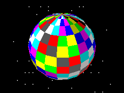
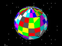
Cautious use of the 16-colour Master System mode
That's the mode the sphere above is rendered in; you can see there's fine detail at its North pole without becoming subject to colour clash and it doesn't fill so much of the screen that we ran out of unique patterns to allocate. As it would be very bad to run out of patterns when attempting to draw text the character set (the 96 characters from 32-127) are permanently allocated as unique patterns which further reduces us to 352 tiles for graphics output.
It's possible to constrain the graphics viewport via VDU 24 to a smaller region which would ensure you never needed more than 352 tiles, as long as your new viewport was properly aligned to the 8×8 grid. For example, 22×16=352 which means that you could have a 176×128 pixel graphics window that you could draw to without risking running out of patterns.
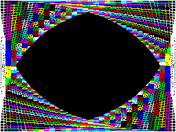
Colour clash in Graphics II (left) versus running out of tiles in Master System Mode (right)
The two screenshots above show the trade-off between colour clash in Graphics II and corruption due to running out of patterns in the 16-colour Master System graphics mode, both caused by running this program:
 10 INPUT "Mode",M%
 20 MODE M%
 30 FOR I%=0 TO 47
 40   GCOL 0,I%
 50   X%=(I%/47)*1279
 60   Y%=(I%/47)*959
 70   MOVE X%,0
 80   DRAW 1279,Y%
 90   DRAW 1279-X%,959
100   DRAW 0,959-Y%
110   DRAW X%,0
120 NEXT I%
130 REPEAT:UNTIL INKEY(0)=-1
140 REPEAT:UNTIL INKEY(0)<>-1
Having to worry about your pattern budget isn't really in the spirit of fun and experimentation. If we're up against hardware and memory limitations I'd rather have a slightly less capable video mode that does at least generate correct output however you use it.
It is possible to completely avoid colour clash if you use the Graphics II mode and simply never use any colour commands, but only having two colours is a bit drab. With a bit of tinkering I came up with another graphics mode that is still using the Master System mode, but reduces the number of colours down to 4. Quite fittingly, a lot of BBC Micro screen modes only supported four physical colours, so I set this new mode to use the same black/red/yellow/white palette by default:
Four colours on-screen at once, no clash and no corruption
In fact, the palette is the whole key to this solution. You may recall that the Master System mode supports two 16-colour palettes. Usually one is assigned as the "background" palette and the other as the "sprite" palette, however each entry in the name table contains a flag that lets you specify which palette the selected pattern should be shown with. In this new video mode, the top half of the screen is assigned to patterns 0-383 using the "background" palette, and the bottom half of the screen is assigned to the same set of patterns 0-383 but to use the "sprite" palette. The palette is then filled with four colours, like this:

Using all 32 palette entries to display four colours on screen simultaneously
The top row is the "background" palette and shows the four desired colours repeating in order four times. The bottom row is the "sprite" palette, and shows that each of the four colours is stretched to fill four consecutive palette entries. This use of repetition effectively turns two bits in each pattern's bitplanes into "don't care" values, depending on which palette is selected.
For example, assume we're in a pattern assigned to the "background" (top) palette and we want to display red. This is colour %01, but as the red entry is repeated we could use use any of colours %0001, %0101, %1001 or %1101 and they'll all come out red – we don't care about the top two bits.
Alternatively, we could be in a pattern assigned to the "sprite" (bottom) palette and want to display yellow. This is colour %10, but it fills the entire palette block from %1000 to %1011, so again we don't care what the lower two bits are, just what the top two bits are.
Using this somewhat redundant palette, we can pack two different four-colour patterns for different parts of the screen into a single sixteen-colour pattern. It's a shame that a halving in bit count ends up quartering the number of colours but I think it's an acceptable solution considering the hardware limitations.
Better drawing, editing, memory and emulation for BBC BASIC on the Sega Master System
Tuesday, 3rd August 2021
I have continued to work on the Sega Master System version of BBC BASIC, and it's feeling much more like a practical version of BASIC than something that was just holding together to run one specific program!
One of the key improvements is to standardise the handling of the different graphics modes. Previously I was using a coordinate system where (0,0) is in the top left corner and all drawing operations were carried out using physical device coordinates (so the screen was treated as being 256 pixels wide and 192 pixels tall). I have now moved the origin (0,0) into the bottom left corner with the Y axis pointing up and scale down all coordinates by 5, effectively making the screen 1280 logical units wide and 960 units tall. This isn't 100% compliant, as the BBC Micro and other versions of BASIC treat the screen as being 1024 units tall, but dividing by 5⅓ is considerably trickier and it would result in the graphics being squished further vertically, so I think using a logical resolution of 1280×960 is an acceptable compromise. I've added some VDU statements to allow you to move the graphics origin as well as define custom graphics and text viewports, so you can control where on the screen graphics and text appear and how they are clipped/scroll.
The output of the "Mandelbaum" program following these changes
I have also changed the default palette to more closely match the one used by the BBC Micro and other versions of BBC BASIC. This isn't too difficult when using the Master System's "Mode 4" as that has a user-definable palette, but the legacy TMS9918A modes have a fixed palette so I've tried to match the default palette as sensibly as I can to the TMS9918A palette. It's possible to change the logical to physical palette mappings under Master System "Mode 4" via a VDU command which writes directly to the CRAM (you can either remap one of the 16 logical entries to one of the stock 16 colours, or supply an RGB value directy to select additional colours) which allows for neat tricks like palette cycling, but the TMS9918A modes currently only let you change the current text/drawing colour, not amend the palette as that's fixed in hardware.
I've also added filled/outlined circle and axis-aligned ellipse PLOT commands using some code written by Darren "qarnos" Cubitt which I originally used in the TI-83 Plus version of BBC BASIC. This code is very capable and fully accepted 16-bit coordinates for its inputs, however it was also originally designed to output to a 96×64 pixel screen so the final plotting was done with 8-bit coordinates ranging from -128..127. Fortunately the Master System's screen also fits in 8-bit coordinates at 256 pixels wide but that's not quite enough information as you also need to be able to tell if a particular point is off-screen (less than zero or greater than 255); simply clipping it against those boundaries will result in a vertical smear on the left or right edge of the screen when drawing outlines. Fortunately I was able to figure out how to modify his code to add some extra clipping status flags to ensure that ellipses were clipped and displayed correctly on any part of the screen.

Filled circles and filled/outlined ellipses make these drawings possible
The only graphics operation exposed by the mode-specific drivers before was a simple "set pixel" routine. This is fine for lines but quite slow for filling shapes so graphics mode drivers can now supply a "fill horizontal span" routine for faster shape-filling. If the routine is left unimplemented a stub routine is provided that fills the span using the "set pixel" routine.
I also added a rectangle-filling PLOT command, which is perhaps not the most exciting-sounding graphics operation but it is used to clear the screen so it is at least useful. More interesting is a triangle-filling routine, something I've never enjoyed writing!
Usually I get very bogged down in the idea that the pixels affected when you fill a triangle should exactly fit within the pixels that are outlined by drawing lines between each of the triangle's points, no more and no less. This can be a bit difficult when the triangle is filled by tracing its edges from top to bottom and drawing horizontal spans between them. If the edge is "steep" (its overall height is greater than or equal to its width) then this isn't too bad, as there's only one X coordinate for each Y coordinate where a pixel would have been plotted. However, when the edge is "shallow" (its overall width is greater than its width) there are going to be certain Y coordinates where the line drawn would have had multiple pixels plotted. In that case, where is the boundary of the horizontal span?
The cop-out answer I've used in the past has been to set up three buffers the total height of the screen and to "draw" the three lines first using the same line-drawing algorithm as the line PLOTting command, keeping track of the minimum and maximum X coordinate for each Y coordinate. When it's time to fill the triangle the minimum and maximum X coordinate for each edge can be determined based on the current Y coordinate and a span drawn between them for perfect triangles. On the TI-83 Plus this takes up four bytes per line (minimum and maximum 16-bit values) for a 64 pixel tall screen, with three buffers for the three lines that comes to 4×64×3=768 bytes, pretty bad. On the Sega Master System that would be 4×192×3=2304 bytes, totally unacceptable on a machine with only 8KB total work RAM!
Each face of this 3D sphere is filled by two triangles.
I've instead simply done my best to interpolate from one X coordinate to the other when working my way down the triangle and filling scanlines, doing a bit of extra pre-incrementing and fudging of initial error values depending on whether it's the top half or bottom half of the triangle. My test was to draw the outline of a triangle in bright white and then to fill a dark blue triangle over the top, if any bright white pixels were visible around the outside this indicated a gap. I mostly got it filled, but I then tried my test program on a BBC Micro emulator and found the BBC Micro exhibited similar gaps so I don't think I'm doing too badly! The above screenshot of the 3D sphere was rendered using this triangle-filling code.
I've also been working on improving the line editor. This is called by BASIC when it's asking for a line of text input from you. Previously I'd only implemented adding characters to the end of the line and pressing backspace to remove characters from the end of the line; if you'd typed in a long piece of code and made a mistake at the start you'd need to backspace all the way to the mistake, correct it, then re-type the rest of the line. Now you can use the cursor keys (or home/end) to move around within the line, insert or overwrite new characters (toggled by pressing the insert key on the keyboard) at the cursor position or backspace/delete characters mid-line as required. It sounds like a small thing but it was quite a lot of code to get right and makes a big difference for usability!
Another feature I've added to aid modifying lines of code is the *EDIT command. This takes a line number as an argument and then brings up the program line you've requested in the line editor, ready for editing. The way this works is a bit sneaky, as it's not natively implemented by BBC BASIC! The trick that makes it work is the ability to override two routines, OSLINE (which BASIC calls when it wants to display the line editor) and OSWRCH (which BASIC calls when it wants to output a character).
When a valid *EDIT <line> command is entered, OSLINE is overridden with the first custom routine. This routine doesn't ask for a line of input, but instead copies L.<line> to the input buffer, overrides OSWRCH with a routine that captures data to RAM, overrides OSLINE with a second custom routine, then returns. BASIC therefore thinks you've typed in a LIST statement so it dutifully starts outputting the line via OSWRCH, but this has been overridden to write the characters to RAM rather than the screen. When it's done this BASIC then calls OSLINE again for the next line of input, which brings up the second custom OSLINE handler. This pulls the data from RAM previously captured by the OSWRCH handler, copies it to the OSLINE buffer, and dispays it on-screen as if you'd just typed it in. It then restores the original OSLINE and OSWRCH handlers before jumping back into the stock OSLINE routine, so you can continue editing the line that you'd requested via *EDIT.
All of this hopefully makes entering programs via the keyboard less cumbersome. Of course, not having to type in programs in full every time you wanted to run them would be even better, and an attempt to give BASIC more memory provides another way to load programs in a somewhat roundabout manner.
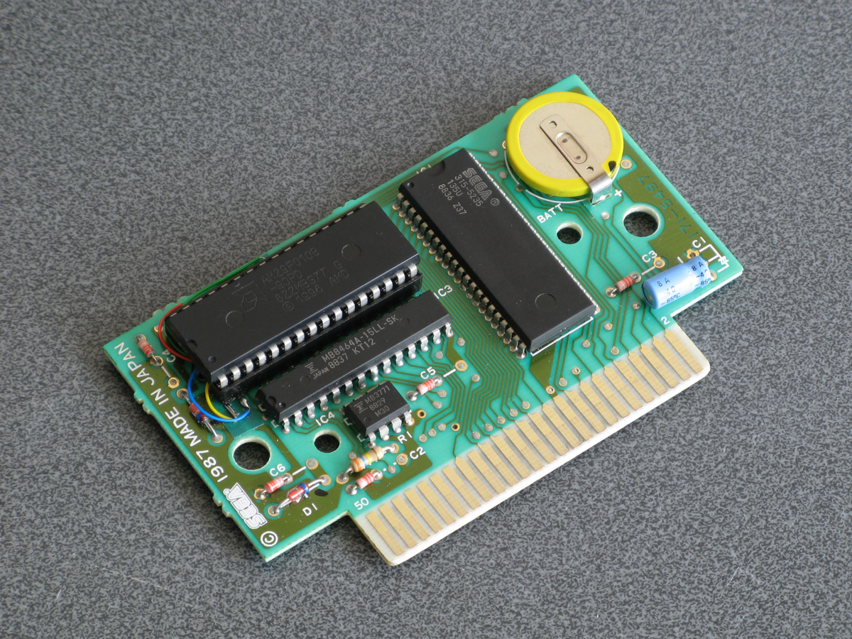
The photograph above shows the modified Monopoly cartridge that I'm now using to test BBC BASIC on real hardware instead of the modified After Burner cartridge I was using before. The advantage of Monopoly is that it has an additional 8KB RAM on board, which is used to save games in progress. Sega's cartridge mapper allows for on-cartridge RAM to be mapped into the address range $8000..$BFFF, immediately below the main work RAM which is at $C000..$DFFF. If present, then, BASIC's memory range (which runs from PAGE to HIMEM) can be extended by enabling the save RAM and moving PAGE down.
$8000..$BFFF is a 16KB range, though, and I mentioned that Monopoly has an 8KB RAM. This is true, and what it means is that the 8KB cartridge RAM is accessible from $8000..$9FFF but is then repeated ("mirrored") from $A000..$BFFF. The cartridge RAM detection therefore has to check two things: firstly that there is RAM in the first place (which can be verified by modifying memory at $8000 and seeing if those values stick) and how big it is (which can be checked by writing to $8000 and seeing if that has also modified the data at $8000+<RAM size>). Once presence of any RAM has been determined during startup, RAM mirroring is checked in 1KB, 2KB, 4KB and 8KB offsets. If any RAM mirroring is detected, then it's assumed the RAM is the size that was being checked at the time, however if not it's assumed that the RAM is the full 16KB. At this point, PAGE (which is $C000 in a stock machine with no cartridge RAM) is moved backwards by the size of the detected cartridge RAM, e.g. to $A000 for an 8KB RAM and $8000 for a 16KB RAM. This results in 16KB or 24KB total available to BBC BASIC, a considerable upgrade from the plain 8KB work RAM!
An added bonus of this is that when you type in programs they grow upwards in memory from PAGE. As PAGE now starts within your cartridge memory, and that cartridge memory retains its contents courtesy of a backup battery, it means that if your entered program is smaller than the size of your cartridge memory you can restore it when you switch the console back on by typing OLD.
That's very well for life on real hardware, but I continue to do most of my development testing in an emulator. I'm having to use my own emulator as there aren't any other Master System emulators that also include a PS/2 keyboard emulator, but I did end up running into a very weird bug. Certain trigonometric functions in BBC BASIC were producing very wrong values, resulting in very odd-looking output.
These shapes are on the wonk
Even though the Z80 emulator at the heart of the program passed ZEXDOC (an instruction tester that checks documented functionality) I remembered that it had failed some aspect of ZEXALL which checks the undocumented flags too. I re-ran ZEXALL and found the problem was with my implementation of the bit instruction, so I worked on fixing that including emulation of the Z80's internal temporary memptr/WZ register to ensure that bit n,(hl) set bits 3 and 5 of the flag register appropriately. ZEXALL now passes, but unsurprisingly it didn't fix my problem (as I didn't really think that BBC BASIC would rely on undocumented functionality!)
I ended up isolating certain exact values that when plugged into SIN() or COS() would produce incorrect results. I then dug out my old CP/M emulator and tried plugging those values into the generic CP/M version of BBC BASIC (which has none of my code in it!) and that produced the same, incorrect, results confirming that the issue was definitely in my Z80 emulation and not in some flaw of the BBC BASIC port.
After tracing through the code and dumping out debug values at certain points and seeing where it differed to a known good reference emulator I found that the fault occurred in FMUL, and from there I found that at some point the carry flag (which is either rotated or added to registers with RR or ADC instructions) was being lost. RR looked fine but digging into my implementation for the 16-bit ADC I found the culprit: the code is the same for ADD and ADC, but in ADC if the carry flag is set then the second operand is incremented by one first. This produces the correct numeric answer, but if the second operand was $FFFF on entry to the function then adding a carry of 1 to it would cause it to overflow back to 0. As this happens before any of the rest of the calculations are made it means that the final value of the carry flag was calculated based on op1+0 instead of op1+$10000, hence the loss of the carry flag.
Fortunately, fixing this fixed the wonky output demonstrated above and I feel slightly more confident in my emulation! Now I can continue working on BBC BASIC, I've had an idea for a screen mode that has a reduced number of colours but will hopefully let you draw anywhere on the screen without running out of tiles causing odd corruption (as happens in the usual 16-colour mode 4) and without attribute clash (as happens in the TMS9918A Graphics II mode)...