Playing VGMs on an STM8S
Monday, 14th December 2009
Following the STM8S tutorial in my previous post, I've tried to put the chip to some practical use. My initial experiments into producing a video signal proved unsuccessful; I managed a static image using hard-coded delay loops, but when trying to use interrupts to trigger the generation of scanlines the timing was all wrong and without an oscilloscope or a working simulator I couldn't find out what was wrong. I decided to turn my attention from picture to sound.
VGM files store game music by logging the data written to the sound chips inside the console or computer directly along with the delay between writes. This results in reasonably small files that are capable of producing excellent sound quality, depending on the way the sound chips are emulated (or, in some cases, not emulated).
I've chosen to focus on the SN76489, a simple sound chip found in a variety of machines including the Sega Master System and BBC Micro. Three of its four sound channels are simple square wave tones, implemented as a 12-bit decrementing counter that flips the state of its output every time it underflows and is reset. Changing the value that is preloaded into the counter when it is reset changes the period of the output square wave, resulting in a change of pitch.
The fourth channel proves rather more of a challenge. It uses a shift register (15- or 16-bit depending on the particular version of the chip) instead of a simple tone counter, and has two modes. When generating periodic noise a single bit shuttles around the shift register, generating a 1/15th or 1/16th duty cycle square wave. This has effect of producing a lower pitch with a distinctive "buzzy" timbre. The other mode is white noise, which uses a feedback system to generate pseudo-random noise.
The emulated SN76489, or PSG, has been implemented in two parts. The first is an interrupt handler written in STM8S assembly for speed. This is executed approximately 44,100 times a second (44.1kHz is the internal time step used in VGM files) and is used to update the internal PSG counters and shift register and generate the output level for that particular sample. Two output levels are generated as I've implemented the Game Gear's stereo extension to the PSG (this simply lets you switch individual channels on or off for each ear). These levels are loaded into capture compare registers for TIM2, which is used in PWM mode to generate the analogue output signals.
The rest of the code is written in C. This includes the second part of the emulated PSG, which handles bytes written to the PSG and updates its internal registers as appropriate.
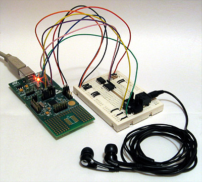
Due to a 16KB limitation with the free version of the Cosmic compiler (and the 32K physical limitation of the microcontroller itself) the VGM file is stored on external EEPROMs which are accessed over the I2C bus via the microcontroller's I2C peripheral. As I don't have any large single EEPROMs, I've used two 32KB EEPROMs, one at address 0xA0 and the other at 0xA2. When the read pointer overflows one EEPROM it automatically steps to the next EEPROM. In theory any size could be supported using this code, but I've used 16-bit variables for all of the file pointers introducing a 64KB limit – this should be easily fixable, but I don't own enough memory to test the code myself, so I've left it as it is for the moment.
// The program I use to split VGM files into 32KB chunks.
// Bear in mind that most VGMs are compressed (VGZ): you'll need to decompress them first.
// You can use 7-zip to do so.
using System.IO;
class Program {
    static void Main(string[] args) {
        var SourceFile = @"D:\Documents\Documents\VGM\StrykersRun-title";
        using (var r = new BinaryReader(File.OpenRead(SourceFile))) {
            for (var i = 0; i < int.MaxValue; ++i) {
                var data = r.ReadBytes(32 * 1024);
                if (data.Length == 0) break;
                File.WriteAllBytes(string.Format("{0} [{1}].bin", Path.GetFileNameWithoutExtension(SourceFile), i), data);
            }
        }
    }
}
To take advantage of the delay between PSG accesses I've implemented a very simple buffering system that queues up a few bytes in advance from the EEPROM. This works well for music, but sampled audio (which involves updating the PSG very rapidly) doesn't work as the code spends too much time waiting for data to be transferred from the EEPROMs.
I've included some recordings of the output below.
- Firetrack (Nick Pelling, BBC Micro)
- Stryker's Run (Martin Galway, BBC Micro)
- Alien 3 – Episode 2 (Matt Furniss, Sega Master System)
- Sega Chess – White Wins (Matt Furniss, Sega Master System)
- Gunstar Heroes – Military on the Max-Power (Kazuo Hanzawa, Hitoshi Sakimoto, M.Yuzuno, M.Yoshida, Y.Mizusawa; Sega Game Gear) [Stereo]
- That Other Final Conflict (RushJet1)
- Alex Kidd: The Lost Stars – I'm the Miracle Ball (Sega Master System) [Sampled speech, doesn't work]
The source code can be downloaded from here. If you do try to run it you'll find that it tends to hang when trying to initialise the EEPROM; this is due to the I2C bus being left in an active state by forcefully terminating the program before debugging. I find it helps to program the board, disconnect then reconnect the power supply to the EEPROMs to reset them, then hitting continue in the debugger.
STM8S-Discovery review and tutorial
Thursday, 3rd December 2009
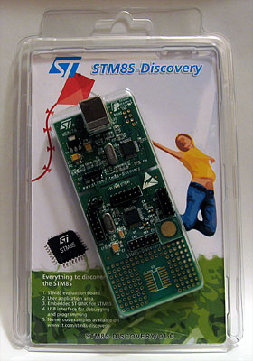
STMicroelectronics recently released the STM8S-Discovery, an exceedingly cheap (RRP $7) evaluation kit for one of their 8-bit microcontrollers. It features the microcontroller itself (an STM8S105C6), running at up to 16MHz and offering 32KB of program memory, 2KB of RAM and 1KB of data EEPROM. This microcontroller has a solid set of on-board peripherals, including four timers (one advanced, one general-purpose, and one basic), SPI, I2C, UART, and ADC – so there are plenty of connectivity options. The device offers up to 38 general-purpose I/O pins.
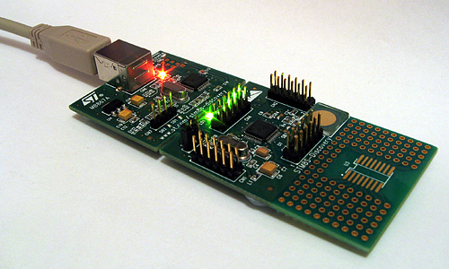
The evaluation board is pretty feature-packed, and includes an integrated ST-LINK for programming and debugging over USB. The circuit board has been designed so that you can simply snap off the ST-LINK part if you'd like to use the microcontroller on its own. Standard 0.1" pin headers are provided to permit you to connect the board to other components, and a small wrapping area is also present. A jumper can be used to select 5V or 3.3V operation.
A green LED and a touch sensitive key are built into the evaluation board; the device comes pre-programmed with a demo program that flashes this LED at different rates when you touch the key.
All in all, a decent piece of kit – but what really sets it apart is its price. ST's recommended price is $7; I bought mine for £4.25 from Farnell. All you need to do is provide a USB A to USB B cable and download the various development tools (Windows only at the time of writing), datasheets and libraries.
 First impressions
I really wasn't expecting much for £4.25, but am very impressed with the hardware. It's solidly built and comes attractively packaged, with clear instructions on the back of the box on how to run the demo program (just plug it in to a USB port!) and where to go next for development tools.
Unfortunately, what appears to be lacking at the moment – not surprisingly for a new product – is guidance for absolute beginners with ST's microcontrollers. Hopefully that will improve as more people get hold of these new kits, as their incredibly low price and self-contained nature makes them ideal for beginners (no need to build up a collection of parts or buy a programmer to get started, just plug and play). I personally found the documentation quite baffling, and judging by a thread on Hack a Day I wasn't the only one.
Disclaimer
I'm not an expert with ST's microcontrollers, but I have at least managed to get something running on the microcontroller after a few frustrating hours spent with the current documentation. The following code may not be the best, but it is simple and it should work (if I've missed anything out or not been clear enough anywhere, please let me know so I can fix it). It doesn't go into any great detail; my assumption is that if you can get some code you've written yourself running on your evaluation board and understand how to use the basic peripherals offered by the microcontroller to work with the board's LED and touch key you should be ready enough to dive into the official documentation and sample code yourself!
Getting started
If you visit the STM8S-Discovery page, you will see options to download various pieces of software and development tools. You'll need to download the following:
- A C compiler (I'm currently using Cosmic's, but it's worth installing the Raisonance compiler too).
- The ST MCU Toolset, which includes the ST Visual Develop IDE.
- The application development package (this contains examples and relevant libraries to access the various peripherals of the chip).
- The STM8S105C6 datasheet (invaluable device specifications/information).
- The STM8S microcontroller family reference manual (a general overview of the STMS8 family, including documentation on the various on-board peripherals).
- The STM8S-Discovery evaluation board user manual (information specific to the evaluation board, including circuit diagrams and other specifications).
There is a document that accompanies the development package, Developing and debugging your STM8S-DISCOVERY application code, which contains instructions on setting up a project – confusingly, these directions don't appear to apply to Raisonance's tool chain, and rely on copying and pasting files from the demo programs. You will need to register the compilers to be able to use them, and Cosmic's registration process is handled by a human so may take some time for you to receive your licence key.
Debugging one of the sample programs
One way to verify that everything is set up correctly and to try out the development tools is to build one of the sample programs included as part of the application development package. In this zip file you will find a directory named STM8S-Discovery_dev; extract this somewhere sensible. Run ST Visual Develop, and select File→Open Workspace. Open the file STM8S-Discovery_dev\Project\Discover\STVD\Cosmic\Discover.stw – this is the project that came pre-loaded onto the evaluation board. If you click Build→Build it should crunch away and after a few seconds should report that there were no errors.
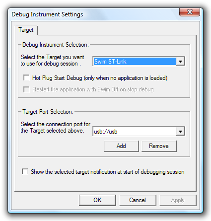
We'll now need to set up the IDE to use your evaluation board's ST-LINK as its debugging instrument. Click Debug instrument→Target Settings and select Swim ST-Link in the dropdown. You can leave the other settings as they are; click OK to close the dialog.
If you now click Debug→Start Debugging (or the blue "D" in the toolbar) the IDE should program the evaluation board and then enter the debugger in "Break" mode. Press Continue (F5) to start running the program; at this point you should be able to use the touch sensitive key on the board to change the rate at which the green LED flashes. When you're done, click Debug→Stop Debugging (or the red cross button in the toolbar) to stop debugging.
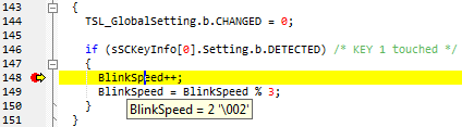
The debugger shouldn't be especially surprising to anyone who has used a graphical debugger (e.g. Visual Studio) before. Try going to line 148 in main.c – BlinkSpeed++; – and selecting Edit→Insert/Remove Breakpoint. Start debugging as before, and you'll notice that when you touch the key this time the debugger breaks on that line. Click Debug→Continue and the program will continue. Marvellous – all pretty intuitive thus far.
Creating your own project
Creating your own project is a rather more involved process, as there's quite a lot you need to set up first. Hopefully this step-by-step guide should help!
- Firstly, click File→New Workspace, and select Create Workspace and Project from the dialog that appears.
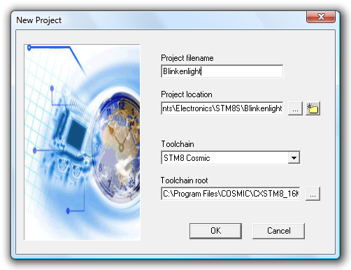
- Now, we need to store our workspace (analagous to a solution in Visual Studio) somewhere; create a new directory for the workspace that is preferably not inside Program Files and give the workspace a name. I'm going to go for "Blinkenlight" as my workspace name.
- Create a new project with the same name as the solution name. It should default to the same directory; keep this as it is. Select STM8 Cosmic as the toolchain.
- Select STM8S105C6 as the microcontroller.
With that done, you should have a shiny new workspace and project containing two files – main.c, containing the entry point for your application, and stm8_interrupt_vector.c, used to associate interrupt requests with interrupt service routines – more on those later. If you build the project and try to debug it you'll note that it does precisely nothing of use. Let's make it do something useful!
Adding the standard firmware library
To access the various peripherals of the microcontroller, ST have provided an extensive standard firmware library. You will need to download this from the STM8S documents and files page; it's the zip archive named STM8S firmware library. Open the zip archive, and copy the FWLib\library folder to your own project folder. You may wish to rename the library folder FWLib, so you should end up with the two folders Project\FWLib\inc and Project\FWLib\src.
There is a folder named project in the firmware library download – copy stm8s_conf.h from this folder into the root of your project folder.
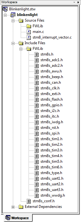
Now, return to ST Visual Develop. Use the workspace panel to the left to create two new folders in your project – Source Files\FWLib and Include Files\FWLib. Add all of the files from FWLib\inc to Include Files\FWLib and stm8s_conf.h to the root of Include Files. You should now have something that looks like this:
You will also need to inform the firmware library that you are using an STM8S105 microcontroller as opposed to the default STM8S208. Here are two ways of doing this – pick whichever seems easiest to you.
- Open stm8s.h in Project\FWLib\inc, comment out #define STM8S208 and uncomment #define STM8S105 near the top of the file.
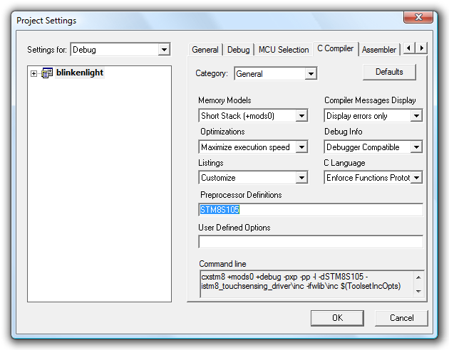
- Pass the definition directly to the compiler by clicking Project→Settings, selecting the C Compiler tab and typing STM8S105 into the Preprocessor Definitions field. You will need to do this twice; once for the Debug configuration and once for Release (select the configuration with the drop-down box in the top left).
Illuminating the LED using GPIO
The cathode of the evaluation board's LED is connected to PD0 on the microcontroller – that is, pin 0 of port D. By driving this pin low we could therefore illuminate the LED. If you consult the documentation for the standard firmware library – it's the stm8s_fwlib_um.chm file in the zip archive – you can see a number of helper functions dedicated to GPIO, or "general-purpose I/O". To use the GPIO functions, we need to do two things:
- Add FWLib\src\stm8s_gpio.c to the project under Source Files\FWLib.
- Enable inclusion of the relevant GPIO header files, achieved by uncommenting #define _GPIO (1) in stms8_conf.h
Both steps will need to be carried out whenever you want to use a new peripheral (e.g. a timer or the UART). Once that's done, you can modify main.c to read as follows:
#include "stm8s.h"

int main(void) {

    // Reset ("de-initialise") GPIO port D.
    GPIO_DeInit(GPIOD);

    // Initialise pin 0 of port D by setting it as:
    // - an output pin,
    // - using a push-pull driver,
    // - at a low logic level (0V), and
    // - 10MHz.
    GPIO_Init(GPIOD, GPIO_PIN_0, GPIO_MODE_OUT_PP_LOW_FAST);

    // Infinite loop.
    for(;;);
}
There are more comments than code there – using the firmware library makes life rather easy, once it's set up! If you start debugging that, you'll note that the LED does indeed light up. It's not much, but it's a sign of life.
Flashing the LED using a delay loop
The GPIO library provides a handy GPIO_WriteReverse() function, which inverts the state of a pin. By toggling PD0, we can make the LED flash. To slow this flashing down at a rate we can see, a delay loop is introduced that delays for 50,000 nops, plus overhead of the for loop structure, between calls to GPIO_WriteReverse().
#include "stm8s.h"

int main(void) {

    // Reset ("de-initialise") GPIO port D.
    GPIO_DeInit(GPIOD);

    // Initialise pin 0 of port D.
    GPIO_Init(GPIOD, GPIO_PIN_0, GPIO_MODE_OUT_PP_LOW_FAST);

    // Infinite loop.
    for(;;) {

        // Delay for a short while.
        u16 d;
        for (d = 0; d < 50000; ++d) {
            // Without a nop() in here, the entire loop would be optimised away!
            nop();
        }

        // Invert the LED pin's state to flash it.
        GPIO_WriteReverse(GPIOD, GPIO_PIN_0);
    }
}
The reason for the nop() is that without it, the compiler optimises away the entire for loop as it does nothing useful.
Well, that's a bit more dynamic, but surely there's a better way to do this than a hard-coded delay loop?
Timers
Timers – of which the STM8S has four with varying capabilities – are an extremely versatile peripheral. They are typically based around a counter, which counts up or down, and various events can be triggered when this counter reaches particular values. We'll start here by using the TIM3 peripheral.
To use TIM3 we need to perform the following steps, as we did previously for GPIO:
- Add FWLib\src\stm8s_tim3.c to the project under Source Files\FWLib.
- Uncomment #define _TIM3 (1) in stms8_conf.h
By default, the microcontroller uses its internal 16MHz RC oscillator ("HSI", or high-speed internal) divided by eight as a clock source. This results in a base timer frequency of 2MHz. When configuring a timer, you can specify a prescaler to further divide the clock frequency – if you were to divide the 2MHz clock frequency by 2000, the timer would count up once every millisecond.
TIM3 restricts the prescaler to powers of two between 1 and 32,768, so we'll use a prescaler of 2048 (that's close enough for jazz). You also need to specify a timer period; this is the value up to which the timer will count before resetting itself. With a period of 999, the timer will run from 0 to 999 before resetting – approximately one thousand milliseconds, or one second, from start to finish.
// Reset ("de-initialise") TIM3.
TIM3_DeInit();

// Set TIM3 to use a prescaler of 2048 and have a period of 999.
TIM3_TimeBaseInit(TIM3_PRESCALER_2048, 999);

// Enable TIM3.
TIM3_Cmd(ENABLE);
Using the standard firmware library allows for easy timer configuration. Now that we have a timer running, we can query its counter value to flash the LED – if it's in the range 0~499, switch the LED on; if it's in the range 500~999, switch the LED off. Building on the ealier source code, here's a program that does just that:
#include "stm8s.h"

int main(void) {

    // Reset ("de-initialise") GPIO port D.
    GPIO_DeInit(GPIOD);
    // Initialise pin 0 of port D.
    GPIO_Init(GPIOD, GPIO_PIN_0, GPIO_MODE_OUT_PP_LOW_FAST);

    // Reset ("de-initialise") TIM3.
    TIM3_DeInit();
    // Set TIM3 to use a prescaler of 2048 and have a period of 999.
    TIM3_TimeBaseInit(TIM3_PRESCALER_2048, 999);
    // Enable TIM3.
    TIM3_Cmd(ENABLE);

    // Infinite loop.
    for(;;) {
        if (TIM3_GetCounter() < 500) {
            // Output a low on the LED pin to illuminate it.
            GPIO_WriteLow(GPIOD, GPIO_PIN_0);
        } else {
            // Output a high on the LED pin to switch it off.
            GPIO_WriteHigh(GPIOD, GPIO_PIN_0);
        }
    }
}
Pulse-width modulation for flashing
One of the many features of these timers is the ability to generate pulse-width modulation – PWM – output on dedicated pins. When this feature is enabled, the timer will set the output pin to one logic level when it starts or restarts and to another when it reaches a used-defined threshold. This is effectively what we're doing in our current program, just manually – far better if the timer could do it for us automatically!
The green LED is connected to PD0, which also acts as TIM3_CH2, or TIM3's channel 2. We can remove most of the code from our previous program, including the GPIO code, leaving us with the following:
#include "stm8s.h"

int main(void) {

    // Reset ("de-initialise") TIM3.
    TIM3_DeInit();

    // Set TIM3 to use a prescaler of 2048 and have a period of 999.
    TIM3_TimeBaseInit(TIM3_PRESCALER_2048, 999);

    // Initialise output channel 2 of TIM3, by setting:
    // - PWM1 mode (starts activated, deactivates when capture compare value is hit),
    // - output is enabled,
    // - capture compare value of 500, and
    // - an active signal is low (0V).
    TIM3_OC2Init(TIM3_OCMODE_PWM1, TIM3_OUTPUTSTATE_ENABLE, 500, TIM3_OCPOLARITY_LOW);

    // Enable TIM3.
    TIM3_Cmd(ENABLE);

    // Infinite loop.
    for(;;);
}
In PWM1 mode, the output starts in the activated state. As we have specified that TIM3_OCPOLARITY_LOW is an activated state, this means that the output will start at a logic low (the LED will be illuminated). When the capture compare value (500) is reached, the output will switch to the deactivated state (logic high) and the LED will switch off. If you run this program as before you will see that the LED does indeed flash on and off automatically.
Pulse-width modulation to change brightness
As the LED is on for approximately 500ms and off for approximately 500ms it is on half of the time. On average, therefore, it is at half its possible brightness. If you modify the 500 in the TIM3_OC2Init function call to 250 and run the program again you will see that on for a quarter of the possible time, and at 750 it is on for three quarters of the possible time. By increasing the rate at which the LED flashes so that it appears to be continuously lit we can control its apparent brightness by adjusting the relative amount of time it is switched on in comparison to the time it is switched off.
We can increase the rate at which the LED flashes by reducing the prescaler of TIM3. Try changing the TIM3_TimeBaseInit call to use TIM3_PRESCALER_16 instead of TIM3_PRESCALER_2048, and change the capture compare value in the TIM3_OC2Init call to 100. When you run your program, the LED on the board will appear to be dimly lit. If you pick up the board and very carefully shake it from side to side you should be able to see that the LED is flashing from the dotted trace it leaves in the air. If you drop the prescaler all the way down to TIM3_PRESCALER_1 you will find that you have to shake the board much faster, but take care not to damage anything!
The brightness of the LED can be modified at runtime by changing the value of the capture compare register with the TIM3_SetCompare2 function.
#include "stm8s.h"

// Short delay loop.
void delay(void) {
    u16 d;
    for (d = 0; d < 150; ++d) {
        nop();
    }
}

int main(void) {

    // Reset ("de-initialise") TIM3.
    TIM3_DeInit();

    // Set TIM3 to use a prescaler of 1 and have a period of 999.
    TIM3_TimeBaseInit(TIM3_PRESCALER_1, 999);

    // Initialise output channel 2 of TIM3.
    TIM3_OC2Init(TIM3_OCMODE_PWM1, TIM3_OUTPUTSTATE_ENABLE, 0, TIM3_OCPOLARITY_LOW);

    // Enable TIM3.
    TIM3_Cmd(ENABLE);

    // Infinite loop.
    for(;;) {

        u16 brightness;

        // Set the brightness from 0 to 999 in a loop (fade up).
        for (brightness = 0; brightness < 1000; ++brightness) {

            // Set the brightness of the LED by modifying the capture compare register
            // for TIM3's channel 2.
            TIM3_SetCompare2(brightness);

            // Delay a short while.
            delay();
        }

        // Set the brightness from 1000 to 1 in a loop (fade down).
        for (brightness = 1000; brightness > 0; --brightness) {

            // Set the brightness of the LED.
            TIM3_SetCompare2(brightness);

            // Delay a short while.
            delay();
        }
    }
}
The above program fades the LED up from the minimum brightness to the maximum brightness then back down again in an infinite loop. It also reintroduces our old enemy, the delay loop, which leads us neatly on to the next subject – interrupts.
Interrupts
Interrupts provide a way to respond to events in a way that doesn't require that we constantly check (poll) the event source. One such event is a timer overflowing – we can use this event to update the brightness of the LED every millisecond without having to poll a timer's counter manually or use delay loops.
We'll use TIM1 to generate the interrupt; it provides a few additional features that are not present on the other timers, but we'll need to keep TIM2 and TIM4 free for later. As before, you'll need to add stm8s_tim1.c to your project and uncomment #define _TIM1 (1) in stm8s_conf.h.
We'll start by adding some skeleton interrupt handler code and reference it in the interrupt vector table to ensure that it is called when the timer updates itself. Firstly, add the two following files to your project:
stm8s_it.c
#include "stm8s.h"
#include "stm8s_it.h"

void TIM1_UPD_OVF_TRG_BRK_IRQHandler(void) {
    // TODO: Implement TIM1 update interrupt handler.
}
stm8s_it.h
#ifndef __STM8S_IT_H
#define __STM8S_IT_H

@far @interrupt void TIM1_UPD_OVF_TRG_BRK_IRQHandler(void);

#endif
These stm8s_it files contain the interrupt request handlers. Interrupt handler functions are called via the interrupt vector table, which is defined in the stm8_interrupt_vector.c file that was automatically generated when you created the project. Open this file and add #include "stm8s_it.h" to the top of it so that it can see your interrupt handler functions. According to the STM8S105xx datasheet the TIM1 update/overflow interrupt is mapped to IRQ 11, so scroll down the table of interrupt vectors and change NonHandledInterrupt on the line marked irq11 (some lines omitted for clarity):
struct interrupt_vector const _vectab[] = {
    {0x82, (interrupt_handler_t)_stext}, /* reset */
    {0x82, NonHandledInterrupt}, /* trap  */
    {0x82, NonHandledInterrupt}, /* irq0  */
    /* [...] */
    {0x82, NonHandledInterrupt}, /* irq10 */
    {0x82, (interrupt_handler_t)TIM1_UPD_OVF_TRG_BRK_IRQHandler}, /* irq11 */
    {0x82, NonHandledInterrupt}, /* irq12 */
    /* [...] */
    {0x82, NonHandledInterrupt}, /* irq29 */
};
Now we have that in place we can start writing the interrupt handler code. Internally, interrupts are signalled by setting a flag in a control register, which the microcontroller periodically checks. If you do not clear this flag the microcontroller will call your interrupt handler again as soon as you return from the function, so you must remember to do so – this is done with the TIM1_ClearITPendingBit(TIM1_IT_UPDATE) function. Using a variable to store the current brightness "direction" (positive to get brighter; negative to get dimmer) the LED brightness could be adjusted every time the timer overflowed using the following code:
stm8s_it.c
#include "stm8s.h"
#include "stm8s_it.h"

s16 brightness_direction = +1; // Start by getting brighter.

void TIM1_UPD_OVF_TRG_BRK_IRQHandler(void) {

    // Get the current brightness.
    u16 current_brightness = TIM3_GetCapture2();

    // Check whether we've hit the maximum/minimum brightness yet.
    if (brightness_direction > 0) {
        // We're currently getting brighter.
        if (current_brightness == 1000) {
            // We're already at the maximum brightness; start getting darker.
            brightness_direction = -1;
        }
    } else {
        // We're currently getting dimmer.
        if (current_brightness == 0) {
            // We're already at the minimum brightness; start getting brighter.
            brightness_direction = +1;
        }
    }

    // Update the brightness of the LED according to the brightness "direction".
    TIM3_SetCompare2(current_brightness + brightness_direction);

    // Clear the interrupt pending bit for TIM1.
    TIM1_ClearITPendingBit(TIM1_IT_UPDATE);
}
We also need to configure TIM1 to generate interrupts. This can be done with the TIM1_ITConfig function, in addition to the existing code used to configure TIM3:
main.c
#include "stm8s.h"

int main(void) {

    // Reset ("de-initialise") TIM3.
    TIM3_DeInit();
    // Set TIM3 to use a prescaler of 1 and have a period of 999.
    TIM3_TimeBaseInit(TIM3_PRESCALER_1, 999);
    // Initialise output channel 2 of TIM3.
    TIM3_OC2Init(TIM3_OCMODE_PWM1, TIM3_OUTPUTSTATE_ENABLE, 0, TIM3_OCPOLARITY_LOW);
    // Enable TIM3.
    TIM3_Cmd(ENABLE);

    // Reset ("de-initialise") TIM1.
    TIM1_DeInit();
    // Set TIM1 to:
    // - use an exact prescaler of 1000,
    // - to count up,
    // - to have a period of 1, and
    // - to have a repetition counter of 0.
    TIM1_TimeBaseInit(1000, TIM1_COUNTERMODE_UP, 1, 0);
    // Set TIM1 to generate interrupts every time the counter overflows (every ms).
    TIM1_ITConfig(TIM1_IT_UPDATE, ENABLE);
    // Enable TIM1.
    TIM1_Cmd(ENABLE);

    // Enable interrupts (no, really).
    enableInterrupts();

    // Infinite loop.
    for(;;);
}
Interrupts are globally disabled by default, hence the need to call enableInterrupts(). If you run this program, you should find that the LED fades in and out as before, but without the need for hacky delay loops. As you can see, TIM1 takes a few additional parameters to its TIM1_TimeBaseInit function; you aren't limited to powers of two for its prescaler, it can count in a number of different ways and you can specify a "repetition count" that will only update the timer registers after a given number of cycles of the counter (in this case, we've disabled that feature).
Touch key input
As well as an LED for output, the evaluation board provides a touch key for input. This requires considerably more computing power to handle than a conventional push switch, but is considerably more interesting! Thankfully, ST have provided a royalty-free library to handle touch sensing keys, sliders and wheels with their microcontrollers which we can use:
- Visit the documents and files page again to download the STM8S Touch Sensing Library; it is packaged as an installer, which should be run.
- Go to the installation directory and copy Libraries\STM8_TouchSensing_Driver to your own project folder as you did for FWLib previously.
- Move Inc\STM8_TSL_RC_Configuration_TOADAPT.h to the root of your project folder and rename it STM8_TSL_RC_Configuration_TOADAPT.h (remove "_TOADAPT").
When you have copied the files, switch back to your project and follow these steps:
- Create a folder Touch Sensing Library under Source Files and add all of the files in STM8_TouchSensing_Driver\Src apart from STM8_TSL_RC_MultiChannelKey.c to it.
- Create a folder Touch Sensing Library under Include Files and add all of the files in STM8_TouchSensing_Driver\Inc to it.
- Add STM8_TSL_RC_Configuration.h to the root of Include Files.
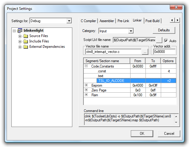
Due to some functions needing to be aligned to even memory addresses, you will need to modify your linker settings. In the IDE, click Project→Settings and switch to the Linker tab. Set the Category dropdown to Input, expand the Code, Constants section and add a section named .TSL_IO_ALCODE with its options set to -r2. You will need to do this to both Debug and Release configurations.
Now we need to go and configure STM8_TSL_RC_Configuration.h for our particular hardware. Open this file, and make the following amendments:
- TIMACQ will need to be changed to TIM2 as we're using TIM3 to drive our LED.
- TIMACQ_CNTR_ADD needs to be changed to 0x530A to match the change to TIM2.
- The touch key is attached to GPIO port C so LOADREF_PORT_ADDR needs to be changed to GPIOC_BaseAddress.
- The load reference is connected to pin PC2, so we need to change LOADREF_BIT to 0x04 (1<<2 = 0x04).
- We only have one key, so change SCKEY_P1_KEY_COUNT to 1.
- The touch key input is connected to PC1, so leave SCKEY_P1_PORT_ADDR at GPIOC_BaseAddress and SCKEY_P1_A at 0x02 (1<<1 = 0x02). As there are no other keys on that port, set all of the other key masks (SCKEY_P1_B to SCKEY_P1_H) to 0.
- As we don't have any keys on a second port, set SCKEY_P2_KEY_COUNT, SCKEY_P2_PORT_ADDR and SCKEY_P2_A—SCKEY_P2_H to 0.
- As we don't have any multi-channel keys, set NUMBER_OF_MULTI_CHANNEL_KEYS to 0.
- The touch key electrodes are connected to PC1 and PC2, so set GPIOC_ELECTRODES_MASK to 0x0A (0b00001010). Set all of the other electrode masks to 0.
Whew, quite a lot of work there! Now we've set that up, we can get programming. Try building your project; it should take a bit longer than before, but not emit any errors if you've set things up correctly!
The first thing we need to change in our program is to switch to running at 16MHz, a requirement of the touch sensing library. To do this, we need to use the CLK peripheral library; add stm8s_clk.c to Source Files\FWLib as before, and uncomment #define _CLK (1) in stm8s_conf.h. Now add CLK_HSIPrescalerConfig(CLK_PRESCALER_HSIDIV1) to the start of your main() function to set the internal high-speed oscillator prescaler to 1 (it defaults to eight). If you now build and run your project you will notice that the LED fades up and down much faster – eight times faster, in fact. Change the TIM1 prescaler to 8000 to revert to the old speed:
#include "stm8s.h"

int main(void) {

    // Set the internal high-speed oscillator to 1 to run at 16/1=16MHz.
    CLK_HSIPrescalerConfig(CLK_PRESCALER_HSIDIV1);

    // Reset ("de-initialise") TIM3.
    TIM3_DeInit();
    // Set TIM3 to use a prescaler of 1 and have a period of 999.
    TIM3_TimeBaseInit(TIM3_PRESCALER_1, 999);
    // Initialise output channel 2 of TIM3.
    TIM3_OC2Init(TIM3_OCMODE_PWM1, TIM3_OUTPUTSTATE_ENABLE, 0, TIM3_OCPOLARITY_LOW);
    // Enable TIM3.
    TIM3_Cmd(ENABLE);

    // Reset ("de-initialise") TIM1.
    TIM1_DeInit();
    // Set TIM1 to use a prescaler of 8000 and to have a period of 1.
    TIM1_TimeBaseInit(8000, TIM1_COUNTERMODE_UP, 1, 0);
    // Set TIM1 to generate interrupts every time the counter overflows (every ms).
    TIM1_ITConfig(TIM1_IT_UPDATE, ENABLE);
    // Enable TIM1.
    TIM1_Cmd(ENABLE);

    // Enable interrupts.
    enableInterrupts();

    // Infinite loop.
    for(;;);
}
Now we've got that organised, we can go ahead with using the touch sensing library. Start by adding #include "STM8_TSL_RC_API.h" to the top of main.c. We need to initialise the library and the touch key in our main function; add the following lines after the CLK_HSIPrescalerConfig call:
// Initialise the touch sensing library.
TSL_Init();
// Initialise the key (we only have one key).
sSCKeyInfo[0].Setting.b.IMPLEMENTED = 1; // It's implemented...
sSCKeyInfo[0].Setting.b.ENABLED = 1;     // ...and enabled.
The touch sensing library makes use of a timer interrupt. We've set TIMTICK to TIM4, so need to attach the TIM4 update/overflow interrupt (IRQ 23) to TSL_Timer_ISR. Open stm8_interrupt_vector.c, add #include "STM8_TSL_RC_API.h" to the top of it, then modify the vector marked irq23:
#include "stm8s_it.h"
#include "STM8_TSL_RC_API.h"

/* [...] */

struct interrupt_vector const _vectab[] = {
    {0x82, (interrupt_handler_t)_stext}, /* reset */
    {0x82, NonHandledInterrupt}, /* trap  */
    {0x82, NonHandledInterrupt}, /* irq0  */
    /* [...] */
    {0x82, NonHandledInterrupt}, /* irq22 */
    {0x82, (interrupt_handler_t)TSL_Timer_ISR}, /* irq23 */
    {0x82, NonHandledInterrupt}, /* irq24 */
    /* [...] */
    {0x82, NonHandledInterrupt}, /* irq29 */
};
Some lines are, as before, omitted for clarity.
The infinite loop at the end of the program will need to be modified to call the TSL_Action function to update the touch sensing library's internal state machine, then check the state of the touch sensing library to see if there's any input to be processed:
// Infinite loop.
for(;;) {
    // Update the touch sensing library's state machine.
    TSL_Action();
    // Check to see if something has happened, and that we're in the idle state before handling it.
    if ((TSL_GlobalSetting.b.CHANGED) && (TSLState == TSL_IDLE_STATE)) {
        // Clear the "something has changed" flag.
        TSL_GlobalSetting.b.CHANGED = 0;
        // Has our key been pressed/detected?
        if (sSCKeyInfo[0].Setting.b.DETECTED) {
            nop(); // <-- Set a breakpoint here.
        }
    }
}
Set a breakpoint on the nop() line, then build and run the program. The LED will fade up and down as before, but if all has gone to plan touching the key should break execution on the nop() line. A slightly more useful program is shown below, modifying the current LED fading code to only fade out and using the touch key to set the LED to its maximum brightness when tapped.
main.c
#include "stm8s.h"
#include "STM8_TSL_RC_API.h"

int main(void) {

    // Set the internal high-speed oscillator to 1 to run at 16/1=16MHz.
    CLK_HSIPrescalerConfig(CLK_PRESCALER_HSIDIV1);

    // Initialise the touch sensing library.
    TSL_Init();
    // Initialise the key (we only have one key).
    sSCKeyInfo[0].Setting.b.IMPLEMENTED = 1; // It's implemented...
    sSCKeyInfo[0].Setting.b.ENABLED = 1;     // ...and enabled.

    // Reset ("de-initialise") TIM3.
    TIM3_DeInit();
    // Set TIM3 to use a prescaler of 1 and have a period of 999.
    TIM3_TimeBaseInit(TIM3_PRESCALER_1, 999);
    // Initialise output channel 2 of TIM3.
    TIM3_OC2Init(TIM3_OCMODE_PWM1, TIM3_OUTPUTSTATE_ENABLE, 0, TIM3_OCPOLARITY_LOW);
    // Enable TIM3.
    TIM3_Cmd(ENABLE);

    // Reset ("de-initialise") TIM1.
    TIM1_DeInit();
    // Set TIM1 to use a prescaler of 8000 and to have a period of 1.
    TIM1_TimeBaseInit(8000, TIM1_COUNTERMODE_UP, 1, 0);
    // Set TIM1 to generate interrupts every time the counter overflows (every ms).
    TIM1_ITConfig(TIM1_IT_UPDATE, ENABLE);
    // Enable TIM1.
    TIM1_Cmd(ENABLE);

    // Enable interrupts.
    enableInterrupts();

    // Infinite loop.
    for(;;) {
        // Update the touch sensing library's state machine.
        TSL_Action();
        // Check to see if something has happened, and that we're in the idle state before handling it.
        if ((TSL_GlobalSetting.b.CHANGED) && (TSLState == TSL_IDLE_STATE)) {
            // Clear the "something has changed" flag.
            TSL_GlobalSetting.b.CHANGED = 0;
            // Has our key been pressed/detected?
            if (sSCKeyInfo[0].Setting.b.DETECTED) {
                TIM3_SetCompare2(1000);
            }
        }
    }
}
stm8s_it.c
#include "stm8s.h"
#include "stm8s_it.h"

void TIM1_UPD_OVF_TRG_BRK_IRQHandler(void) {

    // Get the current brightness.
    u16 current_brightness = TIM3_GetCapture2();

    // If it's brighter than zero, dim it by one unit.
    if (current_brightness > 0) {
        TIM3_SetCompare2(current_brightness - 1);
    }

    // Clear the interrupt pending bit for TIM1.
    TIM1_ClearITPendingBit(TIM1_IT_UPDATE);
}
Conclusion
Now that you've got this far, you should be able to delve into the documentation and samples provided by ST to find out more about this platform. If ST can keep the price as low as they currently recommend, then this is an extremely attractive platform for hobbyists, especially beginners as you don't need any additional tools barring a USB A to USB B cable – I have deliberately avoided interfacing with external components, for that reason. The hardware is extremely capable, low price or not, so I'm sure we'll see many interesting projects created with this board as a starting point!
Further Reading
- Mr Foo has written a useful tutorial on mixing C and assembly.
- m_kisacanin has written a handy beginner's GPIO primer.
- Rich's Words is a blog with articles about the STM8S, including a useful technique to organise interrupt handlers.
Subscribe to an RSS feed that only contains items with the STM8S tag.