Adding Xbox controller support to Light Gun Commando
Tuesday, 24th January 2023
After building a USB Guncon 2 adaptor for my Light Gun Commando project the Xbox seemed like it should be the next console to support as that also uses USB for its controllers. The xboxdevwiki seemed like a good starting point for information about its controller protocol. I wanted to be able to compare against real Xbox controllers too, so I bought an Xbox controller cable online and cut it in half so I could use the plug end to connect my circuit to the Xbox and the socket end to connect Xbox controllers to my PC.
This extension cable proved to be the first hurdle, as connecting an Xbox controller to my PC did absolutely nothing! When I checked the connections I found out why – in spite of the Xbox controller using the USB protocol and official cables using the USB standard colours (plus a yellow wire for video sync), this extension cable used its own colour scheme where +5V was on the black wire and ground was on the red wire. I suppose the moral of the story is to double check with a multimeter before wiring anything up, but fortunately no harm was done!
After connecting the Xbox controllers to my PC I started writing a program to query them using the documentation on the xboxdevwiki. I have put together an application similar to USBView that can display information about a connected Xbox controller, as well as preview the live state of a controller and send output reports to it. The source code for this is available as XboxControllerAnalyser on my Github account, the code is rough and ready as it was really just intended to be my development testbed but I thought it worth sharing in case someone else found it useful.
With a decent grasp of the Xbox's controller protocol, I started implementing a simple controller using the V-USB library on an ATmega328p. This had worked for the Guncon 2, and I was able to build something that worked in my Xbox Controller Analyser application, matching the reports from a real controller.
Unfortunately, I was unable to get the controller working on a real Xbox. Logging the activity it looked like the Xbox would start issuing a few requests, but then give up after a few attempts. The reports I was sending back matched what I could see from a real controller, so I wasn't really sure what the issue was. Real Xbox controllers contain a USB hub, with the being a USB device connected to the internal hub (the other ports on the hub are exposed via the accessory slots on the controller) but my device was a plain USB device directly connected to the console. Maybe that was it?
I think a more likely explanation is that the V-USB firmware is only capable of implementing low-speed USB devices. These limit their endpoint size to 8 bytes (and a maximum poll rate of once every 10ms) whereas the Xbox's input reports are 20 bytes long and the controllers report a poll interval of 4ms. I had set the interrupt endpoint to return the 20 byte reports in 8 byte chunks, and could read these back successfully with a single "read 20 bytes from this endpoint" request on my PC, but maybe the Xbox wasn't so happy about this.
Rather than rely on V-USB's software bit-banged USB I decided to switch to an ATmega32U4 instead, in the form of a cheap Arduino ProMicro board. This is a similar 8-bit AVR chip to what I'd been using already, but has hardware USB support and a good library called LUFA to assist with the USB hardware.
Sure enough, after adapting my code from V-USB to LUFA I was able to get the Xbox responding to a Master System control pad!
Was struggling to get V-USB to mimic an Xbox controller, but yesterday had a go with LUFA on an ATmega32U4 with its dedicated USB hardware and was very happy to finally get it working. Dead or Alive 2 isn't really made to be played on a Master System pad, though! pic.twitter.com/l8G5UHPCI3
— Ben Ryves (@benryves) January 12, 2023
Of course, the real goal here is to implement an Xbox light gun. The xboxdevwiki doesn't provide much particular information about how the Xbox's light guns work, so I needed to connect an original Xbox one to my PC to get a better idea of what was going on. The first thing I noticed is that the guns would not enumerate properly if they were not fed with a video sync signal. This is normally supplied by the Xbox console via the fourth pin in its controller ports (with a yellow wire) and used by the light guns to determine the timing of the video signal and therefore where the gun was aimed. I ended up connecting the Xbox guns to both my PC (VCC, D+, D-, GND) and Xbox (video sync, ground) with the Xbox displaying a bright image on a CRT so I had a good reference for something the gun could "see".
After doing this I found the Xbox light guns would enumerate fully and would send data back to the PC in much the same way that a regular Xbox controller would. There are only really two major differences:
- The controller subtype byte (sent in response to GET_DESCRIPTOR) is set to 0x50 instead of 0x01 for a "Duke", 0x02 for a Controller-S, 0x20 for an arcade stick etc.
- There are three additional bits set in the byte at offset 3 in the input reports (sent in response to GET_CAPABILITIES or GET_REPORT):
enum {
    XID_LIGHT_GUN_LIGHT_VISIBLE = 0x20,
    XID_LIGHT_GUN_UNKNOWN_1 = 0x40,
    XID_LIGHT_GUN_UNKNOWN_2 = 0x80,
} XID_Controller_Input_LightGunFlags_t;
The three additional bits result in a value of 0xE0 in the byte at offset 3 (between the bitmask for digital buttons at offset 2 and the analogue "A" button at offset 4) as reported by GET_CAPABILITIES. I don't know what two of these are for (they were always cleared in the reponse to GET_REPORT), but one (0x20) is the bit that determines whether the light gun can see any light in a frame (set if the gun can see light, cleared if it can't).
Light guns will report their position via the left analogue stick, with (0, 0) being the centre of the screen, (-32768, -32768) being the bottom-left corner and (+32767, +32767) being the top-right corner. If the light gun can't see the screen then it will also report a position of (0, 0) but with bit 5 of the third byte of the report cleared.
Another difference with light guns is that they'll generally report fewer axes and buttons than a regular controller, and will also only report a single force feedback motor. Oddly enough two of my light guns report that they only have a left force feedback motor, but only respond to requests made to the right motor. In practice this still works in games as they set both motors at the same time anyway, but it did strike me as a bit odd!
The House of the Dead III did get a Wii release so playing the Xbox version with a Wii remote isn't a massive achievement, but I'm surprised Silent Scope didn't end up on the Wii as it seems a natural fit for the controller. pic.twitter.com/i0kJtCBORL
— Ben Ryves (@benryves) January 13, 2023
With all this in place I was able to play some House of the Dead III and Silent Scope with my Wii remote, so I was very happy to get it working at long last. There was only one minor complication, which was that I couldn't get past the calibration screen in The House of the Dead without unplugging my circuit, bypassing the calibration with a regular controller, then plugging my circuit back in (Silent Scope had no such issue). After some further debugging it turns out the Xbox was sending a second type of output report to the controller that I wasn't handling, and though Silent Scope didn't care The House of the Dead III wasn't taking kindly to being ignored.
This light gun calibration output report is sent in the same fashion as the force feedback output report (via SET_REPORT) but with a wValue of 0x0201 instead of 0x0200. It's ten bytes in length and takes the following format:
typedef struct
{
    uint8_t bReportId; /**< Report ID. */
    uint8_t bLength;   /**< Size of the report, in bytes. */
    int16_t wInnerX;   /**< X offset to centre calibration target (0, 0). */
    int16_t wInnerY;   /**< Y offset to centre calibration target (0, 0). */
    int16_t wOuterX;   /**< X offset to top-left calibration target (-25000, 25000). */
    int16_t wOuterY;   /**< Y offset to top-left calibration target (-25000, 25000). */
} ATTR_PACKED XID_LightGun_Calibration_Output_Report_t;
Light guns are always calibrated in a two step process, and it's the light gun itself that handles the calibration, not the game software (the light gun should adjust its output to compensate for the calibration values it was previously sent). The first step's centre target is expected to be at (0, 0) and the second step's top-left target is expected to be at (-25000, +25000).
- The game will first send a calibration report with all four offsets reset to (0, 0), (0, 0) to reset any offsets and scaling.
- The game will now display a target in the centre of the screen and ask you to shoot it. This will tell it how "wrong" the gun is when aimed at where it thinks (0, 0) should be on the screen. If the gun normally shoots slightly too high and further to the right, it might report (1000, 3000) for example.
- The game sends a calibration report to the gun to negate the offset, e.g. (-1000, -3000), (0, 0) using our example of (1000, 3000) from before.
- The game will now display a target in at (-25000, 25000) on the screen and ask you to shoot it. This will tell it how "wrong" the gun is when aimed at the top left of the screen.
- The coordinates received from the gun will be subtracted from the expected (-25000, 25000) and sent back to the gun in the second part of the calibration report along with the values previously determined for the centre position. If the first calibration was enough to adjust the screen offset we might have seen the "perfect" coordinates of (-25000, 25000) in which case the report would be (-1000, -3000), (0, 0) again. However, if our gun read the coordinates slightly closer the the middle of the screen at (-20000, 22000) then the report would be (-1000, -3000), (5000, -3000).
All this is fairly academic, as in my case the Wii remote is already calibrated itself and sending "perfect" coordinates back to the Xbox, so I just ignore the calibration values – but by receiving the report rather than just ignoring it The House of the Dead III no longer gets stuck on the calibration screen.
The third and final light gun title for the Xbox is Starsky & Hutch, which is a two-player game where one person drives and the other shoots. It's just about manageable by one player if you have a steering wheel, but I don't have an Xbox wheel. I do have a rather good PlayStation 2 one, however, so after building an Xbox light gun I quickly cobbled together a PlayStation to Xbox controller adaptor and was soon able to drive and shoot my way terribly through Bay City:
Starsky & Hutch provides the opportunity for me to suck at two different game genres simultaneously. Wii remote would be more accurate if I was further from the screen (so it could see more IR LEDs) but I have no excuses for the shambolic driving! pic.twitter.com/yugUrWdHtl
— Ben Ryves (@benryves) January 21, 2023
This adaptor supports the DualShock 2 (including analogue face buttons), DualShock, Dual Analog, neGcon and Jogcon. It's not quite ready for general use (button remapping is currently handled by recompiling the code for specific games, not ideal!) but when I've got it tidied up a bit I'll share it as I was unable to find any other working projects that implement Xbox controllers on cheap microcontrollers.
Supporting Wii remote extension controllers in Light Gun Commando
Wednesday, 4th January 2023
Some light gun games, such as Resident Evil: Dead Aim, require the use of more conventional controller inputs along with pointing a gun at the screen and pulling a trigger. Some light guns have a d-pad in an easily accessible location on the back of the controller to allow for reasonably comfortable control of your character with a thumb, but the Wii remote's placement of the d-pad on the top and near the front makes it fairly awkward to use when held like a gun.
Fortunately, there is an extension controller port on the bottom of the Wii remote that allows the connection of additional controllers such as the Nunchuck or Classic Controller that can be held separately from the gun or clipped onto the Wii remote's gun-shaped holder to bring the controls into a more easily-accessible location. To this end I've been working on implementing support for extension controllers to my Wii remote to light gun adaptor project, which can be seen in the videos below:
The real reason I was mucking around with Wii extension controllers is to add Nunchuck and Classic Controller support. The awkward placement of the Wii remote's d-pad when held like a gun makes a Nunchuck virtually essential for games like Resident Evil: Dead Aim. https://t.co/P5P13j0cKo pic.twitter.com/tjhCosetL1
— Ben Ryves (@benryves) December 29, 2022
The video at the top shows the Nunchuck being used to control the player in Resident Evil: Dead Aim. Once I had added support for the Nunchuck I decided to add support for the Classic Controller too, but as I didn't have one of those at the time I started adding support for different types of extension controller with the only one I had to hand – a uDraw GameTablet. I've always been pretty bad at using graphics tablets as I'm not good at mentally mapping where the pen is on the tablet to where the cursor is on the screen, but maybe playing some light gun games (such as Vampire Night being demonstrated here) with one will improve my skills!
Updating Light Gun Commando to ESP-IDF 5.0 and simulating a Guncon 2
Sunday, 25th December 2022
I've continued working on the Light Gun Commando project that I hope to be able to use as a system for playing light gun games on old consoles with Wii remotes.
The Wii remotes are connected to an ESP32 microcontroller using Bluetooth, and I had a few small issues with this arrangement, most obviously with a cheap third-party Wii remote that refused to pair. I had also encountered a few other quirks and oddities along the way, such as the timer capture's interrupt (used to measure the horizontal scanline period for timing purposes) crashing the whole system if it received too many pulses in a short while (e.g. by inserting or removing the video sync cable producing lots of fast glitchy pulses). I'd found some clumsy workarounds, but when I saw that the ESP-IDF 5.0 development tools for the ESP32 had been released I thought it would be worth updating to that to see if it improved matters.
As well as a lot of improvements and bug fixes ESP-IDF 5.0 did introduce quite a few breaking changes and I couldn't get the project's existing Bluetooth code to compile at all under the new environment. Much of it was based on sample code and rather than try to get this old copied-and-pasted code that I didn't fully understand up to scratch I ended up writing my own code to handle searching and connecting to devices. Fortunately this is quite straightforward to do with the Bluetooth APIs provided, and I even got my cheap 3rd-party knockoff Wii remote to pair alongside my official Wii remotes.
I use the Motor Control Pulse Width Modulator (MCPWM) and Pulse Counter (PCNT) peripherals on the ESP32 to generate the waveforms that approximate what a light gun would see if it was pointed at a CRT based on where the Wii remote is aimed. The old drivers for these peripherals have been deprecated in ESP-IDF 5.0, and though my old code still worked it threw up some compiler warnings and as I'd experienced crashing issues I thought it best to update my code.
I've found the new drivers provide much better control over the peripherals, at least for my use case, and are quite a bit easier to use. I was able to remove some of my clumsy workarounds and improve overall performance, as well as properly handle the timing for a range of different video modes: 240p, 480i, 288p, 576i and 480p are now all supported. Separate sync is now also supported for Dreamcast VGA compatibility, as the following video demonstrates:
Had to rewrite a lot of code to update to ESP-IDF 5.0 but worth it for much more robust video sync code which now properly handles 240p/480i, 288p/576i and 480p. Dreamcast footage below is using newly-supported VGA connection. Even works with red blood now! pic.twitter.com/BfTufkcQwm
— Ben Ryves (@benryves) December 23, 2022
One light gun I hoped to support was the PlayStation 2's Guncon 2. This uses a USB connection and USB is not something I have very much experience with, though I have used V-USB in a few projects before to add USB support — I'd been using standard device classes (e.g. HID or MIDI) where it's a case of simple "fill in the blanks" coding to get a working USB device, rather than a vendor-specific class device like the Guncon 2.
Fortunately I do have a real Guncon 2 and by plugging it into my PC I was able to get a device descriptor from the Windows SDK's usbview. From this I could see the device IDs that I'd need to include as well as see that the Guncon 2 has an interrupt endpoint. Armed with this information I was able to set up a USB device descriptor that closely matched the Guncon 2 by editing V-USB's usbconfig.h.
Of course, having a matching device descriptor is not much use without sending the approprate data back to the console. I'd seen a few places mention that the gun's data is six bytes long: two bytes of button data, two bytes of 16-bit X coordinate data, two bytes of 16-bit Y coordinate data (least significant byte first). I was able to find a mapping of button names to bit indices in the button status data, but nothing clear about the coordinates. I started by just using the same coordinates as the original Guncon, which appears to work for Y but squished the X coordinates into the left half of the screen. I tried doubling the X coordinate range (from 384 units to 768 units) but this seemed a little too wide. I ended up settling on an X coordinate range of 640 units, which seems to provide good results:
One day I'll buy an MCU with native USB but for now V-USB is working its software magic and is pretending to be a Guncon2. As far as I know Virtua Cop is the only PAL PS2 title that requires one, but you have to respect a game that shouts its name at you from the title screen. pic.twitter.com/whFabOhAOQ
— Ben Ryves (@benryves) December 24, 2022
The only USB-handling code I've got in there at the moment is a basic poll/check interrupt ready/write interrupt data loop, though, which is likely not enough to properly implement all of the Guncon 2's functionality. Time Crisis 3 and Virtua Cop: Elite Edition seem happy enough so far, but I'll need to do some further digging into the Guncon 2's USB protocol. I've also ordered an original Xbox controller extension cable to cut in half as I'd very much like to see if I can build an Xbox gun adaptor, and the Xbox uses USB like the Guncon 2.
Light Gun Commando: LCD-compatible light gun support for original console hardware?
Tuesday, 13th December 2022
As the previous entries on this site might indicate, I do enjoy a good light gun game. Unfortunately, when it comes to playing them on home consoles you usually need to use a CRT television for the gun controllers to work. I have a CRT or two at my disposal but I'm well aware they won't last forever and they're not really the most convenient devices even when they are working at their best.
Bearing this in mind I decided to try to find a way to get light guns working on LCD TVs. My experiments back in early 2015 – called DC-LiGuE, the "Dreamcast Light Gun Emulator" – never amounted to much. I was able to build a circuit that I could feed coordinates into and translate that into light gun inputs without involving a CRT display, but I had a couple of major issues. The first was that I was unable to talk to the Dreamcast directly; its controller protocol is much too fast to decode reliably using the ATmega microcontrollers I favour in my projects, so my interface involved shining a bright white LED into the end of a regular Dreamcast light gun. The second issue was disappointment in the Wii remote I was hoping to use as the light gun input; I'd tried some homebrew programs that translated the data from its IR tracking camera into pointer events as well as the Mayflash DolphinBar (which shows up as a regular USB mouse on a PC) and the accuracy was generally pretty poor and not subsitute for a light gun.
More recently I was made aware of other IR-based light gun solutions such as GUN4IR from Boojakascha's YouTube video on the project. I thought I should give the Wii remote another chance! I'd also realised that Mayflash's DolphinBar has a fourth mode intended for use with the Dolphin emulator in which it presents the four paired Wii remotes as four USB HID devices. This makes experimenting with the Wii remote very easy, as you don't need to worry about any of the Bluetooth pairing side of things. I stuck some IR LEDs around my monitor in the GUN4IR configuration and knocked together a quick prototype in C# that analysed the tracked points and translated them into pointer coordinates. Having the four LEDs around the monitor (instead of just two in the Wii sensor bar) makes the aim tracking much easier and much more accurate.
Skipping ahead in the story a bit, the video below shows the C# prototype running in the monitor on the left. The diamond shape is drawn around the four tracked IR emitter points. If the Wii remote is aimed far enough away from the centre of the screen it may lose sight of one or more of these points, but the software does a reasonable job of reconstructing the diamond based on the remaining points it can see. The large bright white dot is the calculated pointer position.
ACTION! Playing PS2 Time Crisis II on an LCD with a Wii remote. At the moment my PC sits in the middle to handle Bluetooth and aim tracking before sending data to a circuit pretending to be a Guncon, so next step would be to replace that with a Bluetooth-enabled microcontroller. pic.twitter.com/GA26q1utgz
— Ben Ryves (@benryves) November 18, 2022
In example the Wii remote is being used to play Time Crisis II on the PlayStation 2. This is a happening on a real PS2, not an emulator on the PC. To achieve this a circuit that mimics a Guncon light gun is connected between my PC and the PS2, and the PC sends button and pointer data to this circuit. Different circuits could be built that could mimic different light guns for different consoles, providing a somewhat universal light gun solution. One issue is that my PC isn't anywhere near my consoles, though, and not everyone is going to have a DolphinBar so replacing the PC side with a dedicated unit seemed like a good idea.
If I was going to use Wii remotes then I'd need something that could speak Bluetooth. The ESP32 microcontroller is cheap and provides a system-on-a-chip with Bluetooth (and a corresponding software stack) that seemed somewhat easy to get into. There was a simple Bluetooth HID host demo that served as a good starting point, and once I'd got the Wii remote paired with the ESP32 and transferring HID reports I translated the C# prototype code I'd written into C and got the ESP32 talking to the simulated Guncon instead of my PC.
Moved all the aim tracking code to the ESP32 so no PC is required. Holding the A button on the Wii remote to pop out of cover was getting tiring so made it automatically hold A if the camera can see any IR lights, allowing me to reload by pointing off-screen. pic.twitter.com/iEn3TS9vAX
— Ben Ryves (@benryves) November 22, 2022
The choice of the PlayStation Guncon was deliberate, as simulating this sort of light gun if you know the pointer coordinates you wish to send is very easy. The Guncon is quite unusual compared to other light guns of the era in that it handles the position calculation within the gun itself and then transfers the coordinates directly to the console over the standard controller protocol used to normally send button statuses or analogue joystick positions. Most other light guns just send a pulse on a dedicated "light gun" input pin when they see flashes of light from the CRT's raster scanning pattern and rely on the console to handle the position calculation, which the console can do as it can ask the video chip which part of the frame it was sending to the TV at the moment the light gun saw the light and from that determine where the gun was aimed. For the Guncon to be able to do this without direct access to the video chip it needs to have access to the generated video signal, which is why the Guncon has an RCA connector on it to pass the console's video signal through it. To be able to make most other light guns work, I'd need to generate the pulses seen when the Wii remote is pointing at the part of the screen that the console is currently outputting, and to do that I'd need to be syncronised with the console's video output.
Fortunately the ESP32 has a motor PWM controller that can be synchronised to external sources and so by adding an LM1881 sync separator circuit to extract the composite (horizontal) and vertical sync pulses to give it something to synchronise itself to I was able to generate pulses that looked like they might have come from a light gun based on the point on the screen the Wii remote was aimed at. I first tested this with the Master System, pretending to be a Light Phaser, before feeding the signals into a circuit that pretends to be a Mega Drive Justifier.
Imitating a Guncon is easy as it reports coordinates to the console, most other light guns send timed pulses when their sensor detects light. My Wiimote adaptor now simulates this light sensor output, synced to the video, and can now hit the broadside of a barn on a Mega-CD. pic.twitter.com/TlsLx9VVo1
— Ben Ryves (@benryves) November 24, 2022
The point I'm aiming for with all of this is to have a central unit sitting under my TV that has the Wii remotes paired to it and the video signal passing through it. It will then have a socket on the front that can be connected to the console-specific light gun simulating cables which will then be plugged into their corresponding consoles. One system that can hopefully cover all the possible combination of light guns on original hardware. When I think of being prepared for any eventuality with a large collection of guns I naturally think of the classic Arnold Schwarzenegger film Commando, and so I've decided to call this project the Light Gun Commando.
Unlike John Matrix, however, I prefer to go into battle with a friend and so it's very important to me that not only does this system cover as many light gun types as possible, but also more than one player. I can't think of any console light gun games that support more than two simultaneous players so at the moment I'm concentrating on two player support but will probably leave space in protocol specifications for more. The following video shows a demonstration of two simultaneous guns in action:
Did any consoles support >2 simultaneous light guns? I've got two Wii remotes working together now, here simulating two Hyper Blaster/Justifier guns plugged into a PlayStation. pic.twitter.com/My8glK4lny
— Ben Ryves (@benryves) December 4, 2022
In the video we're back to the PlayStation, but now simulating a Hyper Blaster instead of a Guncon. This is using the same circuit as the Guncon adaptor, but the firmware now supports different gun modes. Before the main host device sends any data to a console-specific gun adaptor it asks it to describe its capabilities. The adaptor replies with a block of formatted data describing each gun it can simulate; this includes a list of all buttons it has (including a descriptive name and a generic button type such as "trigger button", "start button" or "back button") and any axes it has (such as the pointer X and Y for the Guncon). These gun descriptions can then be repeated for multiple players if an adaptor can simulate more than one gun at a time, and then these player/gun descriptions can be grouped into different modes (e.g. "Two Guncons", "Two Hyper Blasters"). Pressing a button on the host device can then cycle between the different gun modes. The host device can use these mode, player and gun descriptions to construct status reports based on the current state of the Wii remotes, and by using generic button types (e.g. "trigger button" or "start button") the Wii buttons can be mapped automatically to suitable simulated gun buttons.
This automatic mapping is not just a matter of convenience, but is also intended to keep the host device and simulated guns separated. The simulated guns only need to worry about the guns they are simulating and not about button mapping from a Wii remote specifically. This is to allow the host device to be replaced by other hosts but still be able to use the same console-specific adaptors; the idea is that a GUN4IR or Sinden light gun host could be put together in the same way that I'm putting together a Wii remote host, and as long as the communication protocol between them is sensibly designed this should be a pretty straightforward endeavour.
To this end I'm currently trying to hack together as many different simulated light guns as I can to ensure that the communication protocol works well for them all. I've already mentioned the Sega Master System's Light Phaser, Mega Drive's Justifier and PlayStation's Guncon and Hyper Blaster. I did also get the Saturn's Virtua Gun working:
The first home light gun game I played was Virtua Cop on the Sega Saturn, and I remember being amazed by the technical wizardry of the Virtua Gun. Time to take a trip back to Virtua City, this time with a Wii remote in my hand... pic.twitter.com/o4IgxWfprd
— Ben Ryves (@benryves) December 6, 2022
This all started back in 2015 with an attempt to mimic the Dreamcast's Light Gun, though, so if it's nearly eight years later and still no closer to that goal it's surely a bit disappointing? The main problem I had with the Dreamcast is that its controller bus uses a wire protocol that's not directly compatible with any existing standard that might be built into a microcontroller (the PlayStation uses a minor variation of SPI, for example) and is too fast to decode reliably in software on the microcontrollers I typically use. I have seen projects that perform clever tricks to work around this, such as dumping the bus state to RAM in a tight loop before decoding it (slowly) afterwards but these never seemed particularly robust and I didn't want to risk dropping data coming in from the host via the serial port if I was busy spending all available CPU time on speaking to the Dreamcast.
My solution was to look into the dsPIC33, specifically a model capable of running at 140MHz (up to 70 MIPS) which has sufficient grunt to decode the controller protocol in software with cycles to spare, enough RAM to store large data frames and DMA capabilities to be able to keep receiving data from the host device with zero CPU overhead if we're otherwise busy talking to the Dreamcast – all in in a hobbyist-friendly breadboardable DIP28 package!
"...the DEAD!"
— Ben Ryves (@benryves) December 11, 2022
The House of the Dead 2 is my favourite light gun game, so even if it had a native Wii conversion it seemed like the ideal choice to test my Wii remote->Dreamcast light gun adaptor. Need to fine-tune timings and add 31kHz/VGA support but quick lash-up plays OK. pic.twitter.com/0aUzL4v4BV
As the video above hopefully demonstrates, the dsPIC33 seems to have done the trick and I can join the dogs of the AMS and hopefully not suffer like G did.
There's quite a lot work to go but I'm already feeling slightly less worried that if my CRT TVs all conk out I'll be stranded with no way to play my light gun games.
Connecting pedals to a Sega Dreamcast Race Controller
Friday, 30th September 2022
I recently built some Dreamcast Race Controller "De-Dead Zone" mods for people and before popping them in the post I tested them in my wheel. During this process I noticed an unpopulated region of the main PCB:
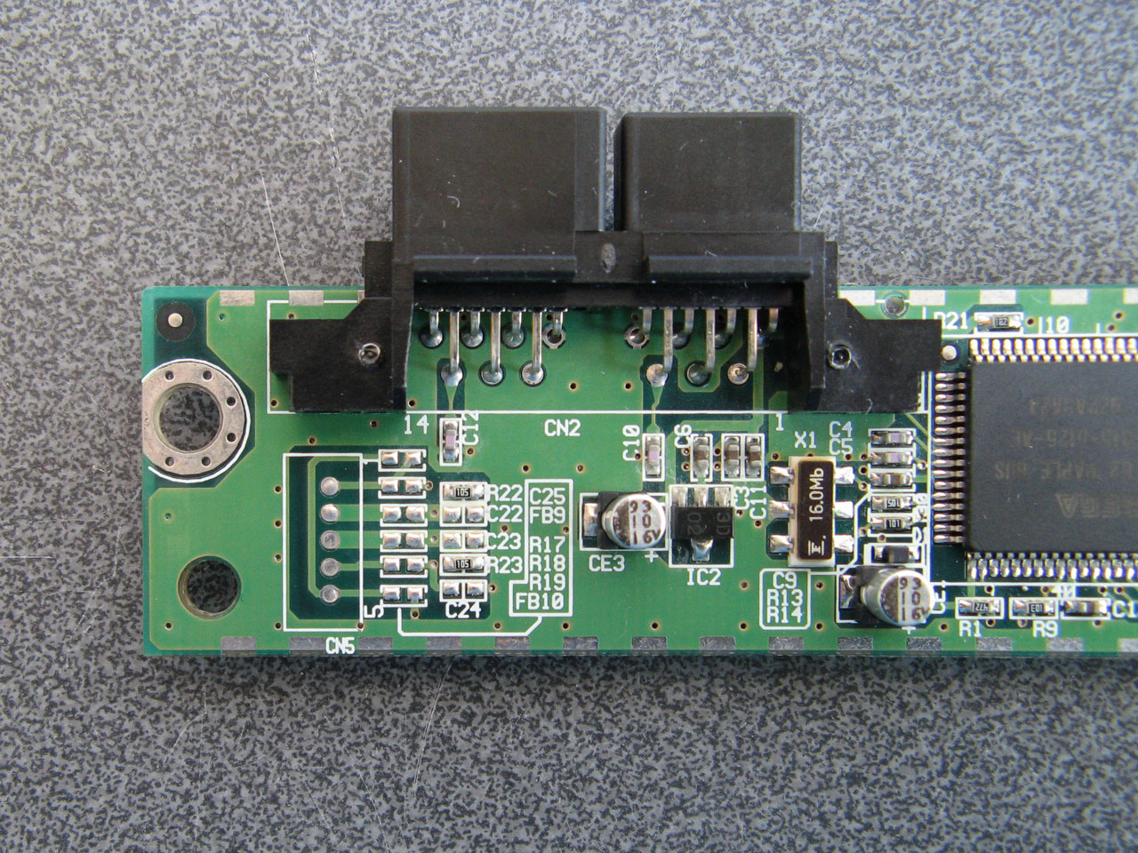
I remember reading that some versions of the Race Controller had a socket on the back for the connection of a set of pedals, however those pedals were never released and games instead rely on a pair of analogue paddles mounted behind the wheel for braking and acceleration. I wondered if the pedal functionality was still available on my wheel, even though it lacks the relevant socket on the back. I traced the connections of the unpopulated components and made a guess of their values, based on their name (e.g. FB9 is presumably a fuse, C22 is presumably a capacitor) and comparing their function to other similar sections of the circuit. This is the circuit I arrived at:
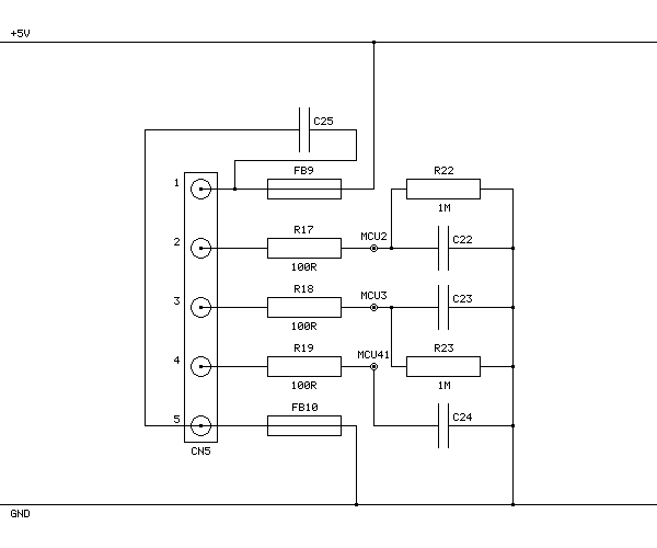
FB9 and FB10 connect +5V and GND to CN5's pins 1 and 5 respectively and are presumably the power connections for the pedals. R22 and R23 are 1MΩ pull-down resistors that were already present, and based on the thick traces from CN5's pins 2 and 3 and connection to two adjacent pins on the main microcontroller these are part of the analogue inputs from the two pedals. CN5's pin 4 is eventually connected to another pin on the microcontroller with a 10KΩ pull-up resistor, and my assumption is that the pedals should connect this pin to ground so the wheel can detect whether they are plugged in or not.
Other parts of the wheel use 100Ω resistors in series with their analogue inputs so I followed their lead. I'm not sure of the capacitor values; I picked 100nF for the C25 capacitor across the power supply lines and 10nF for the capacitors to ground on the other inputs (C22, C23 and C24) but these are complete guesses as I don't own a capacitor meter to test the similar components on other parts of the board.
As I also don't have the small surface-mount parts in stock I connected wire links across FB9, R17, R18, R19 and FB10 and then soldered five wires to CN5 so that I could build a small circuit on a breadboard with the resistors and capacitors on it. I then connected this to my racing wheel pedals:
| CN5 Pin | Function |
|---|---|
| 1 | +5V |
| 2 | Pedal 1 analogue voltage |
| 3 | Pedal 2 analogue voltage |
| 4 | Pedal detect (connect to GND) |
| 5 | GND |
With the pedals connected like this the race controller does detect them and sends their status back to the Dreamcast console, however no game software I have tried has been able to work properly with the pedals. Games either ignore the pedals entirely or complain about an unsupported or disconnected controller. However, if you run the 240p Test Suite's controller tester you can see the pedals reported as two additional axes that operate independently of the existing analogue paddles.
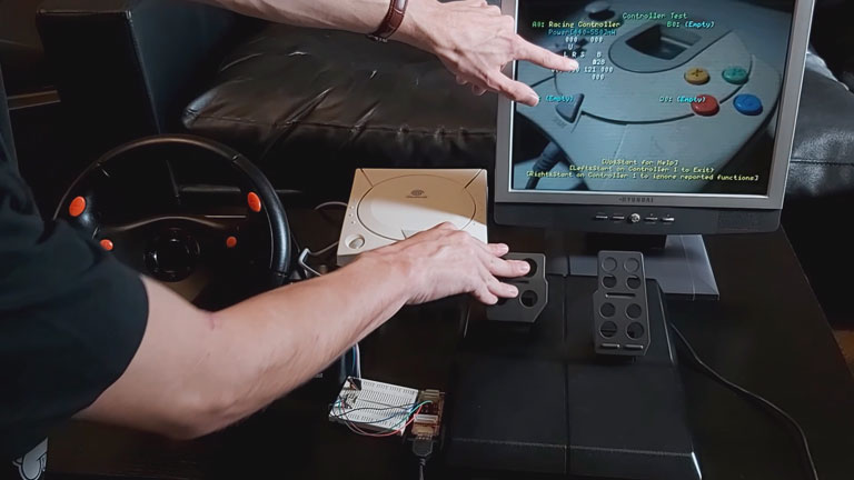
The video above shows a demonstration of how the wheel and pedals perform in a handful of games and the 240p Test Suite, with that test suite being the only software I've found that can show the status of the pedals. It's a bit disappointing that no games seem to support the wheel and pedals together, but I thought it was interesting to see that the functionality is at least present in the wheel hardware.