Taking advantage of interlacing for 3D
Friday, 7th August 2009
To achieve smooth, glitch-free 3D in an ideal world, one would like to be able to alternate between left and right eye views every time the monitor refreshes. You could then use the monitor's vertical synchronisation pulse to alternate which eye shutter is currently open.
Relying on software is not so bad if you can guarantee that you will be able to keep up with the video hardware and output alternating frames without dropping any. This is pretty much impossible with today's complex operating systems running any number of background tasks that could interfere with your render loop at any moment.
Fortunately, video cards already have a mode that is guaranteed to output a different image every frame - interlaced scan. Rather than send each scanline (row) of the image every frame ("progressive scan"), it alternates between sending every even-numbered scanline and every odd-numbered scanline. This halves the vertical resolution, but allows you to double the refresh rate using the same amount of bandwidth.

We can take advantage of this scan mode to encode the left and right views into a single image. The view for the left eye is stored in the even-numbered scanlines and the view for the right eye is stored in the odd-numbered scanlines, as in the image above. When displayed on a monitor using interlaced scan, it appears as the following:
As the video card takes care of alternating which set of scanlines (or field) is displayed, the result is that the left and right views alternate perfectly in time with the monitor's refresh rate.
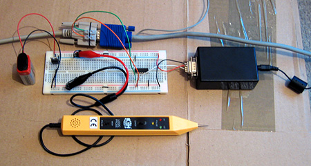
To test this, I've attached a counter IC to the vertical synchronisation pulse of a VGA monitor. The low bit of the counter toggles every time the screen refreshes, and this is used to select which eye shutter is open on the 3D glasses. The glasses are driven using the serial port adaptor described in the previous post.
The result is perfectly stable 3D images. The circuit does not know which field, and hence which eye's view, is visible at any time - it just alternates left and right, which means that there is a 50% chance that the left and right views are flipped. This can be fixed by switching the circuit off then on again to try and resynchronise, but a better solution would be to add a switch to toggle the uncovered eye manually and to fix the synchronisation. As this would only need to be done once per session this isn't much of an issue! An alternative fix would be to add a switch to switch the left and right views in software.
The logic probe in the above photo is an integral part of the design - at least, I assume it is, as if I remove it the circuit doesn't work correctly! I assume there's a noise issue that's interfering with the circuit (none of the unused inputs on the counter chip are tied low) and the logic probe contains some noise suppression circuitry of its own.
The only real fly in the ointment here is video driver support for interlaced scan modes. My video card only supports 1920×1080 at 30i, 29i and 25i, and only if the primary monitor is an LCD. I can work around the problem by cloning the primary LCD to the CRT and setting both to 1920×1080 at 30i, but my LCD displays a warning message and makes a distressing noise and 30i, whilst faithful to the Master System's 30fps 3D, is unpleasantly flickery. It would be wonderful if I could drop the resolution down a bit and switch to 60i, but I can't see a way to do that with ATi's drivers.