A temporary solution for 3D games on the Master System without the 3D glasses adaptor
Monday, 29th July 2019
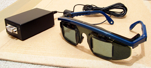
I bought my Sega Master System-compatible 3D glasses almost exactly ten years ago for use in my LCD Shutter Glasses Adaptor project.
More recently I've acquired a CRT television and an actual Sega Master System so I could in theory make use of the glasses as I had originally intended - with Sega Master System games.
I've been keeping an eye on eBay for the 3D Glasses Adaptor for the Master System. This is a device that plugs into the console's card slot and allows it to drive the glasses with the software controlling which LCD shutter is open and which is closed by writing to the card. Unfortunately, these cards are not too easy to find in the UK and when they do appear they usually came bundled with a broken pair of glasses (it seems very unusual for both arms to still be attached to the glasses, and I've seen a fair few pairs that are cracked down the middle too). I already own some compatible 3D glasses so didn't want to waste money on buying a broken set of original Master System ones!
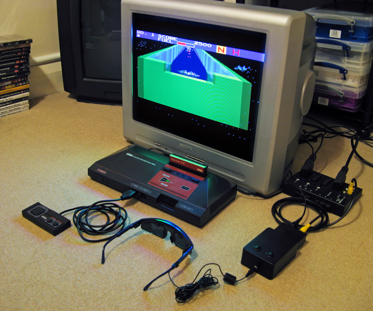
I did eventually find someone selling a loose adaptor for a reasonable price so bought it and a few games. Zaxxon 3-D was the first to arrive and I was eager to test it out. Without the card adaptor I needed to find an alternative solution, so my thoughts turned to the LCD Shutter Glasses Adaptor I'd built a few years ago.
This is designed to sit between a PC and a VGA CRT monitor and drives the shutter glasses, alternating which LCD shutter is open and which is closed every vertical sync. It can also blank out alternate scanlines, simulating an interlaced signal from a progressive one by blanking odd scanlines on one frame and even scanlines on the next, but this is not useful in our case. The Master System is already alternating complete left and right eye views on its own, so we just need to catch its equivalent of a vsync pulse and feed that into the VGA port on the back of the shutter glasses adaptor.
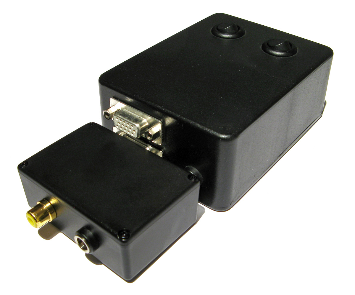
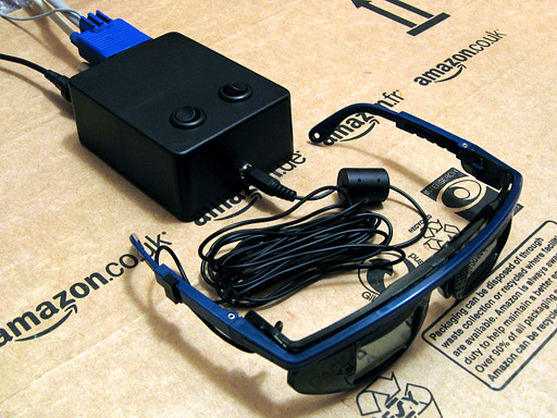
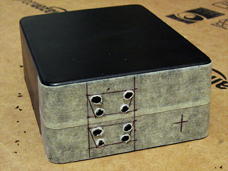
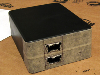
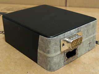
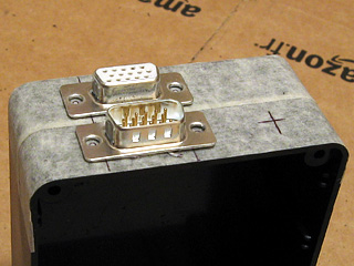
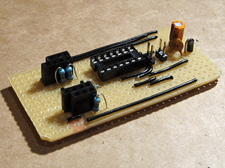
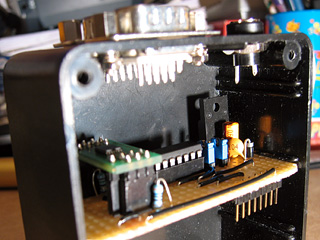
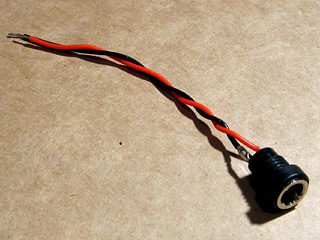
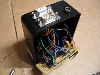
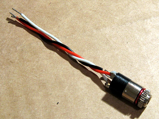
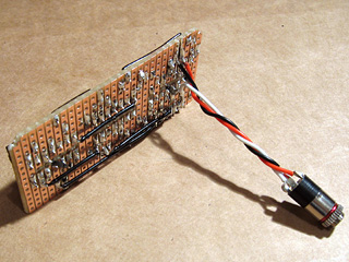
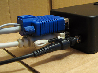
Above is the device I built, attached to the existing 3D glasses adaptor. It has a single composite input which should be connected to the composite output from the console, either via a splitter (if the console is connected to the TV using composite video) or via some sort of SCART breakout box (I'm using the composite video output from my SCART switch box). It also has a power socket which is used to power the circuit inside which is also passed through to the LCD shutter glasses adaptor. The box has a DE-15 connector and 5.5x2.1mm barrel plug on the other side for connections:
I'd cut the barrel plug off a faulty power supply years ago, I'm glad I kept it as it made the project a much neater solution than it might have other been!
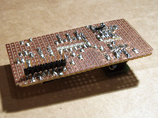
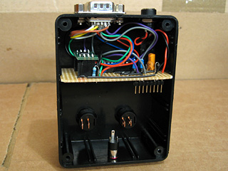
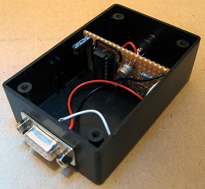
The circuit inside is very simple indeed. As the original adaptor has its own 5V regulator inside and is designed to be powered from a 9V power supply I had to maintain the same convention for this device, so I use a 7805 regulator to convert the incoming voltage to 5V. This powers a textbook example of an LM1881 sync separator circuit - I'm using the reference circuit from the chip's datasheet, connecting the composite video input to the chip's composite video input via a 0.1µF capacitor (without termination as it's assumed the signal is being terminated by the TV) and I use the LM1881's composite sync output and vertical sync output for the VGA connector's horizontal and vertical sync connections respectively.
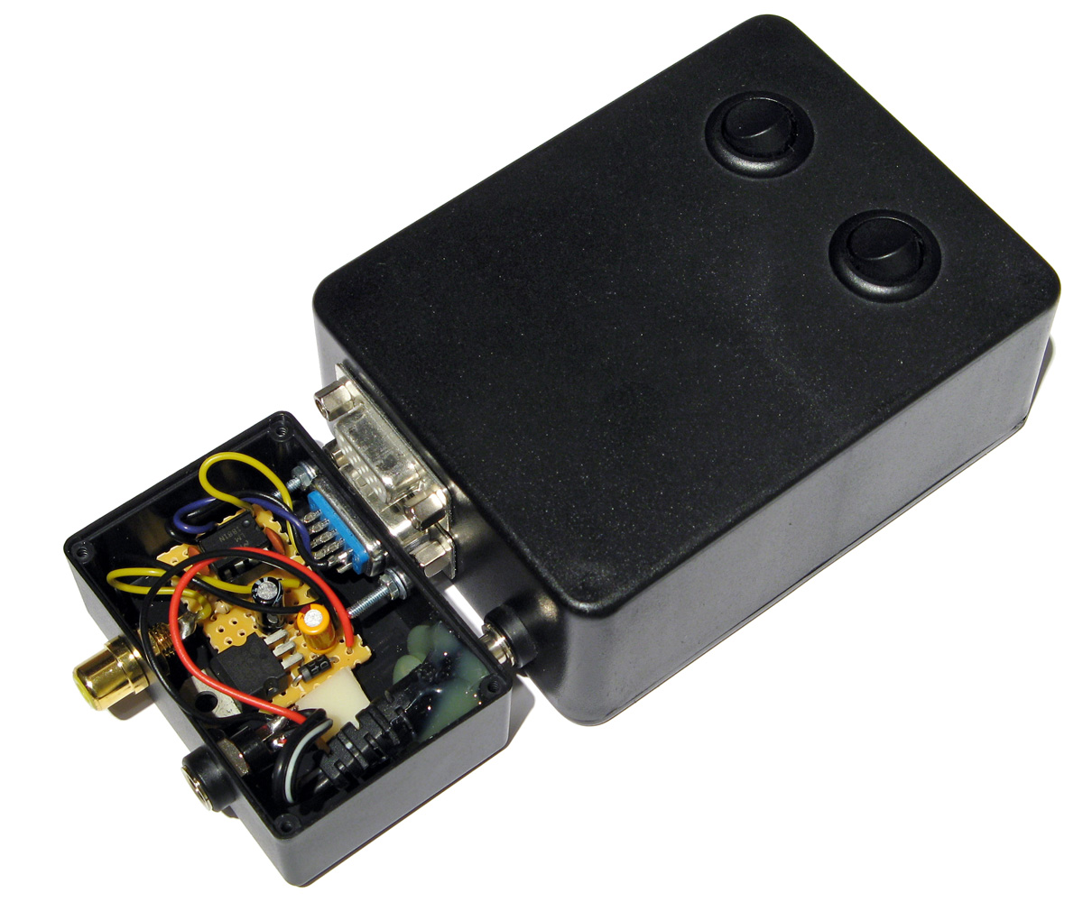
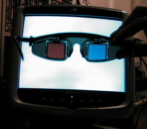
The circuit can be seen above, stuffed in the bottom of the box - along with copious amounts of hot glue to keep the barrel plug in place! How well does it work? Well, the below animation shows two views of the circuit in action, viewed through first one shutter and then the other of the 3D glasses:
This isn't a perfect solution - the Master System expects to be able to explicitly specify which shutter is open whereas in our case we're simply be alternating every frame. This could mean that the eyes are swapped, however there is an eye swap switch on the shutter glasses adaptor to compensate. If the view looks wrong then the switch can be used to correct it, and once that's done as long as the software alternates the views every frame then it should be fine.
I'm certainly happy for now, as it lets me play my 3D games whilst waiting for the console's intended 3D glasses adaptor to arrive in the post.
Building a VGA line blanker and 3D glasses driver
Monday, 15th February 2010
Assembling a circuit on breadboard is a good way to experiment with electronics, but the result is not something you could really use – it's bulky, fragile and awkward to set up. It's far nicer to solder the components of the circuit together to form a more permanent device and put it in a enclosure to make it robust. This is not something I'm especially good at, but something I thought I'd try with the VGA line blanker and LCD shutter glasses controller I've been experimenting with recently.
In the past I've struggled along with a hand drill and the nail file on a Swiss Army knife, but have more recently acquired a high-speed rotary tool and an assortment of attachments which make things much easier. I took some photos when building this project, which I've documented below; I'm not sure my techniques are very efficient, but I do get there in the end. I'd be very glad to hear any advice anyone has!
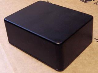
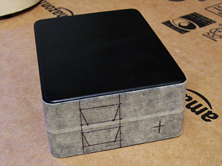
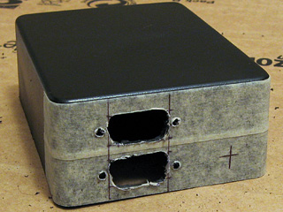
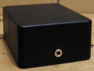
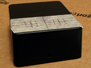
I started with a plain project box. Having planned roughly where I was going to put the VGA ports and DC power socket, I covered one side of the box in masking tape and drew on where I was going to put the holes.
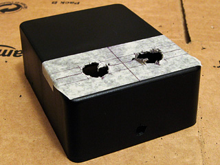
To cut straight-edged holes, such as those required for a D-subminiature connector, I drill a hole in each corner and use a small cylindrical burr to cut between the holes. This leaves a very rough edge, but is a good start.
I then widen the hole using a large cylindrical burr and a needle file until the part I'm attempting to mount fits snugly.
When I had both VGA connectors in place, I marked and drilled the holes for the jack posts that the VGA leads will screw into. Neither hole is especially neatly cut, but the D-subminiature connector overlaps the hole sufficiently to hide any shoddy workmanship.
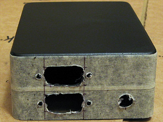
The last part of the back is the DC power socket. As I don't have a drill bit large enough to cut the hole on its own, I drill it as large as I can then widen it using the cylindrical burrs mentioned before. With all of the holes cut, I inserted the components to see how they look and identified one problem – I'd underestimated how fat the connectors on the end of VGA leads are. Fortunately, I have a slim VGA cable that fits, but a regular sized one does not – in future I'll need to remember to put the VGA connectors further apart!
With that mistake fresh in my mind, I thought I'd move onto something a bit more difficult to get wrong – the 3.5mm stereo jack on the front of the box to plug the glasses into. This is just another round hole, cut in the same way as the DC power socket.
The two control switches on the top of the box require much larger holes. These were cut in the same way as before – a small hole is gradually widened by using a cylindrical burr. This is a very tedious job, not helped by having to keep stopping to clean the melted plastic that adheres to the burr.
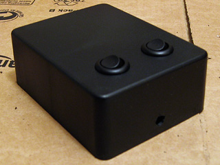
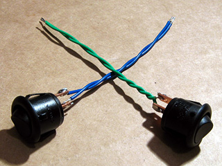
Finally, the switches were installed. I was originally going to use latching push buttons, but had previously used those nice round rocker switches as the power switch on the AVR TV Game project so opted to use them instead.
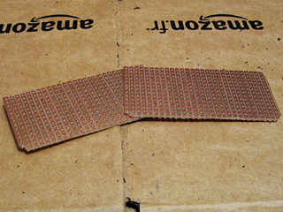
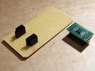
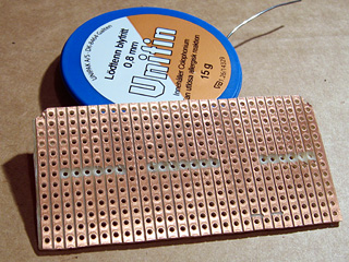
The final bit of physical work was to cut some stripboard down to size to fit inside the enclosure. These were cut by first scoring along the tracks where the cut was to be made, then snapping the board over the edge of a table. This results in a clean break, but to ensure a snug fit the boards were tidied up with a sanding drum. The lid (or, in my case, base) of the enclosure has a raised edge that fits inside the box, so the sanding drum was also used to remove two of the corners of the stripboard pieces to allow the base to fit.
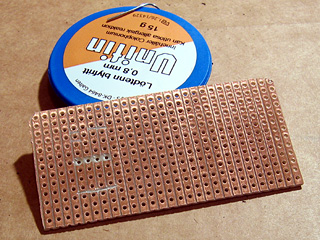
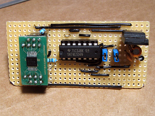
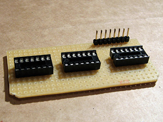
The next stage was to move onto the electronics, and I started with the circuit board that was to host the video amplifier IC, voltage regulator and Schmitt trigger on vsync/hsync. The video amplifier is attached to a TSSOP14 adaptor that has a D-shaped pin configuration, with two rows of four pins and two rows of three pins. Having cut through the tracks in the stripboard to mount the amplifier, I needed to find some suitable pin sockets.

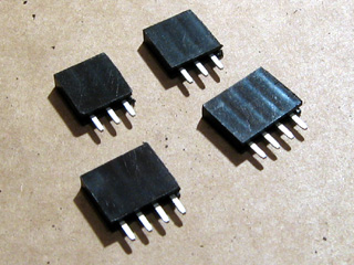
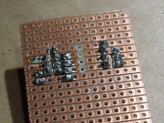
As I don't have any pin sockets with just three pins in them (only two, four and eight) I cut two eight-way pin sockets in two with a pair of wire cutters then tidied up the ragged edges with a sanding drum and needle file.
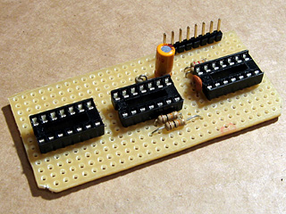
With the pin sockets soldered in place you can see the D shape I mentioned above. I don't generally plan stripboard circuits very thoroughly, preferring to start by placing large components in approximately the right location with respect to where the external connectors are and how they need to relate to other components. Once those are in place I add smaller components (such as discrete resistors or capacitors) before finishing by adding the wire links to connect all of the parts together. This does lead to situations where I wish that I'd placed a component one hole along to give myself more space or to avoid having to insert so many wire links, but it generally works.
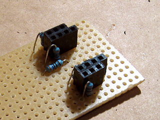
With the video amplifier in position, I added the resistors that are required on its inputs and outputs. To keep the circuit reasonably compact I cut through stripboard tracks between the holes using a conical HSS burr with a small tip – this is an especially useful tool when you need to deal with double-row pin sockets
I then added the support circuitry for the voltage regulator (smoothing capacitors and a rectifier diode to protect the circuit if the polarity of the power supply is incorrect) and a socket for the Schmitt trigger IC. I find the easiest way to keep components in place on any sort of through-hole board is to tape them down firmly with masking tape before soldering – bending the legs out makes the parts much harder to remove if you make a mistake. Blu-Tack is easier to use but has a habit of melting when soldering and leaving an unpleasant blue residue on your circuit, so I'd advise against it! To make this part of the circuit slightly more future-proof a pair of jumpers are used to connect the sync lines (vsync and hsync) from the VGA input and VGA output together. These could be removed if I decided to change the logic board to override these signals – for example, as part of a sync-doubler, which injects a vsync pulse half way down the screen.
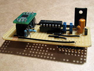
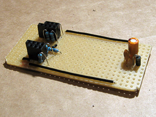
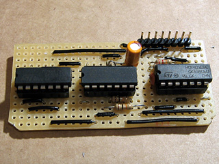
I finally added the bulkiest components; the 5V regulator and the pin header to connect the upper and lower boards together. Soldering pin headers to the underside of a board is a fiddly job, but is required in this instance to connect the bottom of the upper board to the top of the lower board.
With the upper board completed it was time to put it into the enclosure and solder the VGA connectors and DC power socket to it. This is the part I least enjoy.
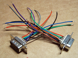
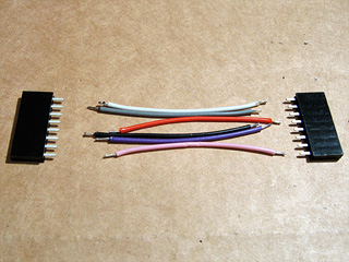
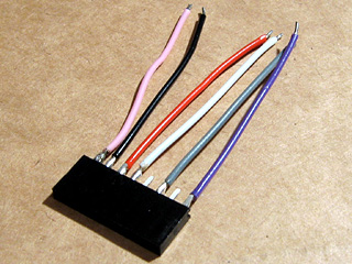
I started by soldering some stranded wire to the VGA connectors. Most of the wires are the same length, as they are required to carry signals to and from the circuit, but some wires are shorter and only connected to one of the VGA connectors. These are the white, yellow, orange and brown wires in the above photo, and these are attached to pins used to exchange information between the PC and the monitor (e.g. supported resolutions and refresh rates). As we're not interested in these, they're connected straight through from one connector to the other.
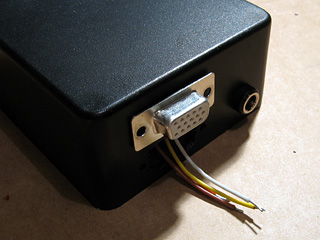
I inserted the VGA connector with these identification pins into the top hole, passed the shorter identification wires through the other and soldered them to the second VGA connector. This leaves the red, green, blue, vsync, hsync and ground pins loose inside, ready to be connected to the upper circuit board.
The DC power socket also needs to be connected to the circuit board, but at only two wires that's a much simpler job.
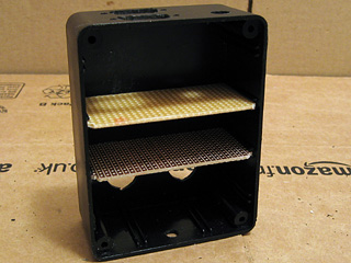
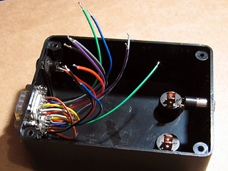
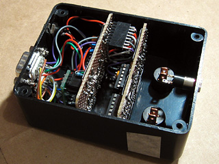
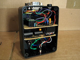
All of the loose leads are soldered onto the circuit board and stripboard is slotted into place inside the enclosure. The wires could be shorter, but that would have made soldering them a bit harder.
The lower circuit board will host the main logic for the project – it receives the vsync and hsync signals, and uses these to control whether the video signal should be blanked or not, and which shutter on the glasses should be closed and which should be open. It also contains the oscillator that generates the AC voltage that drives the glasses. I arranged the three logic ICs roughly next to eachother according to their layout on the breadboard version of the circuit and cut the stripboard tracks as appropriate.
I started by adding the sockets for the ICs and pin header to connect this circuit board to the video amplifier one, then added the discrete components. As before, I taped the components down before soldering them in place to make the task easier. Being able to copy the circuit directly from the breadboard version also made the task much easier.
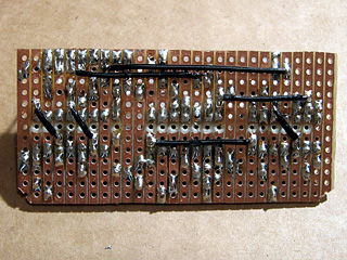
The last step for this part of the project was, as before, adding the wire links. Rather than run long wires around ICs I found it more practical to solder a few wires onto the underside of the stripboard.
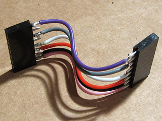
The two circuit boards needed to be connected together somehow. Without the facilities to make a proper ribbon cable, I just soldered some lengths of stranded wire (rather messily) between two pin sockets. As I'm not outputting anything to vsync or hsync (I'm feeding the input sync signals straight back to the output via the jumpers previously discussed), I didn't need to connect anything to these pins – hence the apparently missing wires in the photos.
The cable to connect the two boards together needed to be bent to fit – it's getting snug, but everything's in there without having to be forced, which is a good sign.
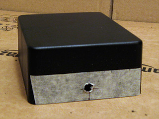
The next job was to attach the 3.5mm stereo jack that the LCD shutter glasses are plugged into. This is pushed through the hole in the enclosure from the inside and screwed on from the outside, so it can be soldered directly to the circuit board without having to thread it through the hole first. The small red "washer" is a length of enamelled wire that has been bent around the thread of the jack socket and is used as a spacer – without it, quite a lot of the thread protrudes from the front of the box, looking rather untidy.
Last of all are the two control switches. These are soldered to the track side of the stripboard like the stereo jack, but must be snapped through their holes in the enclosure first, which is why they were left until last. Everything is slotted into place, the base of the enclosure is screwed on, and the project is pretty much complete.
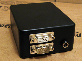
The VGA cables don't fit especially well – the D-subminiature sockets are a bit too close to eachother. If I use a thin VGA extension cable and wiggle the leads I can just about get both to screw in.
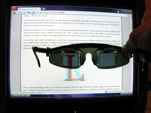
The demonstration pattern from some previous ramblings of mine is quite useful for testing 3D glasses, and by holding the left eye of the shutter glasses to the screen you can see that only the "L" part of the image is let through.
3D glasses, a VGA line-blanker and fixing Quake
Wednesday, 3rd February 2010
Some time ago, I posted about using interlaced video to display 3D images. Whilst the idea works very nicely in theory, it's quite tricky to get modern video cards to generate interlaced video at a variety of resolutions and refresh rates. My card limits me to 1920×1080 at i30 or 1920×1080 at i25, and only lets me use this mode on my LCD when I really need it on a CRT. Even if you can coax the video card to switch to a particular mode, this is quite a fragile state of affairs as full-screen games will switch to a different (and likely progressively scanned) mode.
3D glasses adaptor with line blanker prototype
An alternative is to build an external bit of hardware that simulates an interlaced video mode from a progressive one. The easiest way of doing that is to switch off the RGB signals on alternate scanlines, blanking odd scanlines in one frame and even scanlines in the next. This type of circuit is appropriately named a line blanker, and my current implementation is shown above. It sits between the PC and the monitor, and uses a pair of flip-flops which toggle state on vsync or hsync signals from the PC. The output from the vsync flip-flop is used to control which eye is open and which is shut on the LCD glasses, and is also combined with the hsync flip-flop to switch the RGB signal lines on or off on alternate lines using a THS7375 video amplifier. Unfortunately, this amplifier is only available as TSSOP, which isn't much fun to solder if you don't have the proper equipment; I made a stab at it with a regular iron, the smallest tip I could find, lots of no-clean flux and some solder braid. I have been informed that solder paste makes things considerably easier, so will have to try that next time.
My cheap LCD glasses lack any form of internal circuitry, merely offering two LCD panels wired directly to a 3.5mm stereo jack, and so I'm using the 4030 exclusive-OR gate oscillator circuit to drive them.
The adaptor provides one switch to swap the left and right eyes in case they are reversed, and another is provided to disable the line blanking circuit (useful for genuine interlaced video modes or alternate frame 3D). You can download a schematic of the circuit here as a PDF.
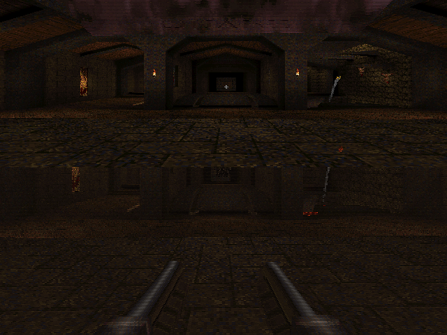
I've been using these glasses to play Quake in 3D, which is good fun but an experience that was sadly marred by a number of bugs and quirks in Quake's 3D mode.
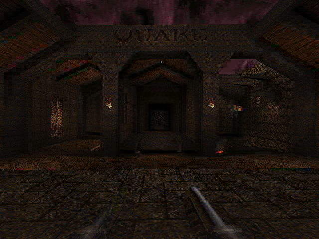
WinQuake, demonstrating the crosshair bug and excessive stereo separation of the weapon
The most obvious problems in the above screenshot are the migratory crosshair (appearing 25% of the way down the screen instead of vertically centred) and the excessive stereo separation of the player's weapon.
If the console variable LCD_X is non-zero, Quake halves the viewport height then doubles what it thinks is the stride of the graphics buffer. This causes it to skip every other scanline when rendering. Instead of rendering once, as normal, it translates the camera in one direction, renders, then offsets the start of the graphics buffer by one scanline, translates the camera in the other direction then renders again. This results in the two views (one for each eye) being interleaved into a single image.
The crosshair is added after the 3D view is rendered (in fact, Quake just prints a '+' sign in the middle of the screen using its text routines), which explains its incorrect position – Quake doesn't take the previously halved height of the display into consideration, causing the crosshair to be drawn with a vertical position of half of half the height of the screen. That's pretty easy to fix – if LCD_X is non-zero, multiply all previously halved heights and Y offsets by two before rendering the crosshair to compensate.
WinQuake, demonstrating the DirectDraw corruption bug
A slightly more serious bug is illustrated above. When using the DirectDraw renderer (the default in full-screen mode), the display is corrupted. This can be fixed by passing -dibonly to the engine, but it would be nice to fix it.
After a bit of digging, it appeared that the vid structure, which stores fields such as the address of the graphics buffer and its stride, was being modified between calls to the renderer. It seemed to be reverting to the actual properties of the graphics buffer (i.e. it pointed to the top of the buffer and stored the correct stride of the image, not the doubled one). Further digging identified VID_LockBuffer() as the culprit; this does nothing if you're using the dib rendering mode, but locks the buffer and updates the vid structure in other access modes. Fortunately, you can call this function as many times as you like (as long as you call VID_UnlockBuffer() a corresponding number of times) – it only locks the surface and updates vid the first time you call it. By surrounding the entire 3D rendering routine in a VID_LockBuffer()…VID_UnlockBuffer() pair, vid is left well alone, and Quake renders correctly in full-screen once again.
The final issue was the extreme stereo separation of the player weapon, caused by its proximity to the camera – it does make the game quite uncomfortable to play. The game moves the camera and weapon to the player's position, then applies some simple transformations to implement view/weapon bobbing, before rendering anything. Applying the same camera offset and rotation to the player weapon as the camera when generating the two 3D views put the weapon slap bang in the middle of the screen, as it would appear in regular "2D" Quake. This gives it the impression of a carboard cutout, and can put it behind/"inside" walls and floors when you walk up to them; I've added a console variable, LCD_VIEWMODEL_SCALE, that can be used to interpolate between the default 3D WinQuake view (value: 1) and the cardboard cutout view (value: 0).
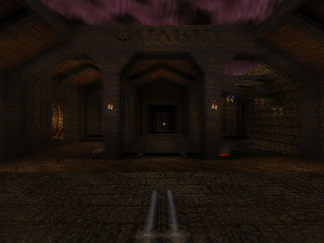
WinQuake with the 3D fixes applied
You can download the replacement WinQuake from here – you can just overwrite any existing executable. (You will also need the VC++ 2008 SP1 runtimes, if you do not already have them). Source code is included, and should build in VC++ 2008 SP1 (MASM only appears to be included in SP1, which is required to compile Quake's extensive collection of assembly source files).
If you don't have a copy of Quake, I recorded its looping demos in 3D and uploaded them to YouTube. This was before I made the above fixes, so there's no crosshair or player weapon model in the videos – if you have access to YouTube-compatible 3D glasses or crossable eyes, click here. 
Taking advantage of interlacing for 3D
Friday, 7th August 2009
To achieve smooth, glitch-free 3D in an ideal world, one would like to be able to alternate between left and right eye views every time the monitor refreshes. You could then use the monitor's vertical synchronisation pulse to alternate which eye shutter is currently open.
Relying on software is not so bad if you can guarantee that you will be able to keep up with the video hardware and output alternating frames without dropping any. This is pretty much impossible with today's complex operating systems running any number of background tasks that could interfere with your render loop at any moment.
Fortunately, video cards already have a mode that is guaranteed to output a different image every frame - interlaced scan. Rather than send each scanline (row) of the image every frame ("progressive scan"), it alternates between sending every even-numbered scanline and every odd-numbered scanline. This halves the vertical resolution, but allows you to double the refresh rate using the same amount of bandwidth.

We can take advantage of this scan mode to encode the left and right views into a single image. The view for the left eye is stored in the even-numbered scanlines and the view for the right eye is stored in the odd-numbered scanlines, as in the image above. When displayed on a monitor using interlaced scan, it appears as the following:
As the video card takes care of alternating which set of scanlines (or field) is displayed, the result is that the left and right views alternate perfectly in time with the monitor's refresh rate.
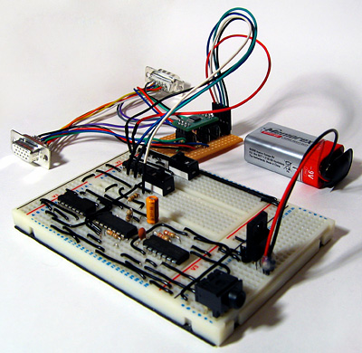
To test this, I've attached a counter IC to the vertical synchronisation pulse of a VGA monitor. The low bit of the counter toggles every time the screen refreshes, and this is used to select which eye shutter is open on the 3D glasses. The glasses are driven using the serial port adaptor described in the previous post.
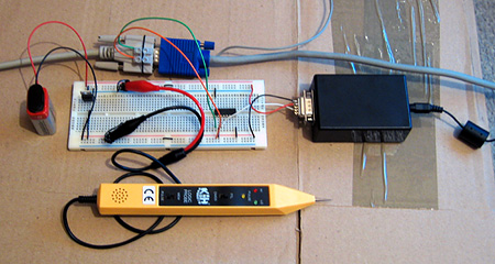
The result is perfectly stable 3D images. The circuit does not know which field, and hence which eye's view, is visible at any time - it just alternates left and right, which means that there is a 50% chance that the left and right views are flipped. This can be fixed by switching the circuit off then on again to try and resynchronise, but a better solution would be to add a switch to toggle the uncovered eye manually and to fix the synchronisation. As this would only need to be done once per session this isn't much of an issue! An alternative fix would be to add a switch to switch the left and right views in software.
The logic probe in the above photo is an integral part of the design - at least, I assume it is, as if I remove it the circuit doesn't work correctly! I assume there's a noise issue that's interfering with the circuit (none of the unused inputs on the counter chip are tied low) and the logic probe contains some noise suppression circuitry of its own.
The only real fly in the ointment here is video driver support for interlaced scan modes. My video card only supports 1920×1080 at 30i, 29i and 25i, and only if the primary monitor is an LCD. I can work around the problem by cloning the primary LCD to the CRT and setting both to 1920×1080 at 30i, but my LCD displays a warning message and makes a distressing noise and 30i, whilst faithful to the Master System's 30fps 3D, is unpleasantly flickery. It would be wonderful if I could drop the resolution down a bit and switch to 60i, but I can't see a way to do that with ATi's drivers.
3D LCD Shutter Glasses Experimentation
Wednesday, 5th August 2009
The Sega Master System supported 3D LCD shutter glasses to provide a more immersive (if somewhat flickery) playing experience. Having caught wind of an eBay member selling compatible glasses for $9 and being rather interested in stereoscopy I decided to experiment a little for myself.
The glasses are pretty simple; they consist of two LCD panels that can be "switched on" to block light from passing through to each eye. A 3.5mm stereo jack plug provides the electrical connection.
To display the 3D image you alternate between showing the image for the left eye and the right eye on the monitor, uncovering the corresponding eye immediately before the image appears on the monitor. This effectively halves the refresh rate (and results in fairly noticeable flicker when run at the standard NTSC 60Hz) and prevents the 3D glasses from working with displays that respond too slowly (eg LCD panels). I've had to dig out my old CRT monitor for this project. Even if my LCD did refresh quickly enough, its polarisation is perpendicular to the polarisation of the shutter glasses, meaning that no light can pass from the LCD through the glasses even when both eye LCD panels are switched off.
The adaptor I'm using is based on this circuit (I'm using the second variation with the variable resistor to fine-tune the driving frequency). The LCD panels require an AC voltage, and using a EOR gate as an oscillator allows the whole device to be constructed out of a single IC with a handful of external components. More importantly, being based on an existing and public design allows me to ensure that any work I do should be compatible with adaptors other people have built.
The DTR pin on the serial port supplies power to the circuit and the RTS pin is used to choose which LCD panel is switched on to cover an eye.
Test pattern seen through glasses
The above image displays a test pattern viewed through the glasses. The software alternates between clearing the screen to red with the left eye shutter open and clearing the screen to cyan with the right eye shutter open. The colours were deliberately chosen to match the colours of the common anaglyph glasses. As the colours are alternated very quickly (in the interests of avoiding a headache I used a refresh rate of 120Hz) the screen appears a light grey colour to the naked eye.
Most LCD shutter glasses appear to use some form of feedback from the video signal to synchronise the alternating of eyes. On a PC they could alternate every time the vsync signal appeared on the VGA port, on a TV they could open the correct eye shutter depending on the current field of the interlaced image that was being displayed. The Sega Master System's video chip can generate an interrupt when entering the vblank period which you can use to prepare the next frame and update the glasses. An adaptor connected to the PC's serial port has no such luck - I have not yet found a way to reliably synchronise the glasses to the refresh rate.
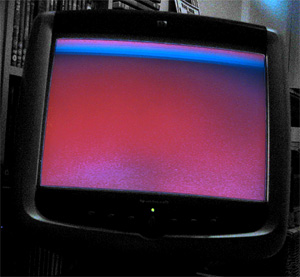
Poor synchronisation (and even worse photography) results in images like the above, as seen through the left shutter. As the LCD shutters have been updated too late, some of the display intended for the right eye is seen through the left eye at the top of the display - the cyan band in this case.
So far, the best result I've had is to use Direct3DEx's DeviceEx, which provides a handy WaitForVBlank method. Less handy is the Vista requirement, as is the slight delay between returning from this function and updating the serial port, resulting in a flickering band near the top of the display as per the previous photograph. For the best results I need to set the presentation interval to "immediate", which compounds the issue with occasional tearing caused by the delay between WaitForVBlank returning and calling Present.
Switching the presentation interval back to "1" (tying the refresh rate of the render loop to that of the monitor) results in complete frames (no tearing or bands of the wrong colour/image), but the additional delay before presenting the next frame puts updating the LCD glasses out of sync by one frame. As the uncovered eye should alternate between subsequent frames one can simply uncover the "opposite" eye to uncover the correct image, but any dropped frames throw this out of sync and you get the occasional "inside out" view when the wrong eye is uncovered. Any background tasks on the PC kicking in could potentially cause a dropped frame. This is one reason that a VGA pass-through adaptor that automatically alternates the uncovered eye every frame wouldn't work, as it would get thrown out of sync by these dropped frames.

A demo compatible with the Sega 3D glasses, showing the images for each eye as stereo pair
The advantage of using an existing adaptor design makes me reluctant to pursue solutions that involve additional hardware to fix the problem. One possible solution I can think of would be an additional pass-through box that contains a simple latch that is clocked by the VGA vsync signal between the serial port and the glasses adaptor. You could then set the state of the glasses immediately before calling Present, safe in the knowledge that your signal will only get through to the adaptor box perfectly synchronised with the CRT's vertical refresh, assuming the CRT doesn't enter vblank between updating the serial port and calling Present. Not having to manually synchronise to vsync in software would remove the need for the Vista-only Direct3DEx too.
Subscribe to an RSS feed that only contains items with the LCD shutter glasses adaptor tag.