Highlighting and tape loading PC-1500 BASIC programs on the web
Friday, 9th May 2025
I don't think I've had a proper dose of "man-flu" since COVID and I haven't missed it at all. This journal entry has been written in a state of sleep deprivation whilst being tanked up on Lucozade and Lemsip (expiry date: March 2020) so hopefully it still makes some degree of sense.
In my current state the most obvious project is to subject myself to the banshee howls of tape loading. I've implemented some degree of tape loading support to my site before by taking tokenised BBC BASIC programs and running them through a web service that converts them to UEF files that can be played back in the browser with PlayUEF, and with my recent interest in the Sharp PC-1500 it would seem like a sensible idea to do something similar for that computer.
Unfortunately, whilst PlayUEF is a superb piece of software for loading Acorn software, it is less ideal for the Sharp PC-1500. This isn't a limitation of the UEF format itself, it's just that Sharp PC-1500 programs are stored at a different base frequency (1270Hz instead of 1200Hz), use a 0° phase instead of 180° phase, and repeat the wave patterns for 0 bits and 1 bits four times longer than the BBC Micro format ("300 baud" mode instead of "1200 baud" mode). None of those features were supported by PlayUEF, however it is open source software so I hacked them into my own fork of the project.
Note that I do say "hacked", as PlayUEF does take some shortcuts when generating the resulting waveform that I found a bit awkward to work around. For example, it needs to allocate a buffer to write the wave file to and so needs to know the number of samples in the resulting wave file to do so. It normally does this by multiplying the number of wave cycles in the file by the number of samples per cycle, but that only works if the number of samples per cycle remains constant through the file (which they won't if we're changing the frequency on the fly) and the number of cycles per bit also needs to remain consistent (which it won't if we're outputting four times as many wave cycles for the Sharp PC-1500 when compared to BBC Micro).
In the end I worked around this with a two-pass solution: the first time around a zero-byte buffer is allocated and written to (which appears to work?) and the final length is calculated by adding up the total number of samples. The second time around the buffer is allocated the total number of samples it requires.
Whilst this works and the end result loads fine onto an actual Sharp PC-1500, the code is now a bit of a mess and there are a lot of nifty visualisations and "fast loading" tricks that only make sense to the BBC Micro but are still baked into PlayUEF. For my own use I might make a less sexy alternative to PlayUEF that just converts a UEF to a wave for loading via the web. However, for now it works as-is.
To support all this I also needed way to tokenise (and detokenise) Sharp PC-1500 BASIC programs and convert the resulting binary into a UEF tape image. To do this I've knocked together a couple of PHP classes, sharp_pc1500_basic and sharp_pc1500_tape that do the work and these files can be downloaded in sharp-pc-1500-php.zip.
Here are some examples of how this works (click the "Load file as tape image" to hear the beautiful sounds):
Relocatable Quick-Tape installer for the Sharp PC-1500
Saturday, 26th April 2025
After my previous journal post about faster saving and loading of Sharp PC-1500 programs to and from tape I discovered that I was using a somewhat out-of-date version of Sharp Pocket Tools. The later version I upgraded to adds support for the "SuperTape" and "Quick-Tape" formats, and also includes copies of the PC-1500 programs for those formats.
Both formats appear to support file names and verification of the recorded data (a minor gripe I had with the Fast Load was its lack of these features). SuperTape apparently manages even higher speeds, though at the cost of somewhat more RAM than Fast Load (711 bytes, or 761 for the full version with the ability to merge a program with the existing one in memory, instead of Fast Load's 540 bytes). Quick-Tape seems to be about the same speed as Fast Load, but actually consumes less memory overall (only 508 bytes). Quick-Tape also explicitly supports saving machine language programs by specifying a start and end address, something that I cannot see is supported with the SuperTape format, though it looks like it might support loading machine language programs if the correct load address is stored in the file.
Based on my experiences with Fast Load and the documentation that accompanies SuperTape and Quick-Tape I came up with a rough feature comparison table (I can't claim it's completely accurate, as it's based on what I've gleaned from the documentation):
| Format | Fast Load | SuperTape | Quick-Tape |
|---|---|---|---|
| Speed | Fast | Fastest | Fast |
| Filenames | ✗ | ✓ | ✓ |
| Verification | ✗ | ✓ | ✓ |
| Machine language | ✗ | (Maybe?) | ✓ |
| Variables | ✓ | ✗ | ✗ |
| RAM usage (bytes) | 540 | 711–761 | 508 |
| Relocatable | ✓ | (Partial) | ✗ |
To get a rough idea of speed I tried converting the Globe application to a wave file. Both Fast Load and Quick-Tape produce a file that's 30 seconds long — a huge improvement over the seven minutes that the native cassette routines take. SuperTape still manages to blow both of these out of the water with a file that's only 13 seconds long! Only Fast Load seems to have the ability to save BASIC's variables to tape, though this is not a feature I personally have any use for.
The ability to relocate the machine language routines that make up the tape routines is a very important one, however! The available range of memory addresses in a PC-1500 computer will depend on which memory expansion module is installed and whether any other machine language routines are also loaded. Fast Load can be relocated to anywhere you want in memory via its BASIC installer program. SuperTape has a few different versions for different starting addresses based on certain memory modules as well as a BASIC installer, however as far as I can see it doesn't seem to allow being loaded at an arbitrary address which would make it trickier for it to coexist alongside other machine language programs on the computer. Quick-Tape doesn't have any relocation support at all, only working if loaded to address &00C5 and used with the CE-161 memory expansion module.
However, Quick-Tape seems like it would otherwise be ideal — it consumes the last RAM, it seems the most feature-complete and though it's not quite as fast as SuperTape it's still a massive improvement over the native cassette routines.
I therefore decided I'd try to make a relocatable version of Quick-Tape. To assist with this I first disassembled it using lhTools. It doesn't load any data nor jump to any absolute addresses within its own memory space, which is a good start — in fact, it only calls three subroutines inside itself: &01BE, &01BF and &01CF. You can spot these easily in the disassembled code as they are assigned named labels by lhTools instead of absolute addresses, for example in this snippet:
lbl_0_159:
	SJP	lbl_0_1be ; labelled address inside our memory
	ADR	Y
	LOP	lbl_0_159
	LDA	YH
	SJP	lbl_0_1bf ; labelled address inside our memory
	LDA	YL
	SJP	lbl_0_1bf ; labelled address inside our memory
...as opposed to:
lbl_0_117:
	SJP	BBD6 ; absolute address outside our memory
	VMJ	0A
	SJP	BBC0 ; another absolute address outside our memory
The version of lhTools I'm using is one I've modified to use the standard LH5801 instruction mnemonics instead of the Z80-inspired ones it normally uses; it also disassembles vectored subroutine calls into standard VMJ instructions instead of the lhTools pseudo-instructions, though as I haven't got it to re-assembled these instructions properly yet this is not something I'm able to share just yet. However, the important thing here is the subroutine called with the SJP instruction.
Now that we know where these subroutine calls are, a BASIC program can be written that patches the loaded machine language program with the correct target addresses for where it's been relocated to. Similarly, the reserve program (which contains BASIC CALL statements to call the entry points in the machine language program) needs to have its addresses patched to point at the relocated machine language program. The resulting installer looks like this:
    10 M=PEEK &7863*256+197:B=PEEK &7865*256+PEEK &7866
    20 IF B-M<508 PRINT "No room": END
    30 L=M: IF B-M>508 WAIT 0: PRINT "Load @";L;" ";: INPUT L
    40 CLS : WAIT : IF (L<M) OR (L+508>B) PRINT "Bad address": GOTO 10
    50 WAIT 0: PRINT "Play QUICK-TAPE...": CLOAD M"QUICK-TAPE";L
    60 FOR I=1 TO 3: READ A,C: FOR J=1 TO C
    70 READ O: POKE O+L,(A+L)/256,(A+L) AND 255
    80 NEXT J: NEXT I
    90 DATA 249,1,149,250,2,157,161,266,3,411,443,452
   100 M=M-197: PRINT "Play QUICK-RESERVE...": CLOAD M"QUICK-RESERVE";M
   110 FOR I=1 TO 6: READ A,O:A$=RIGHT$("00"+STR$ (A+L),5)
   120 FOR J=1 TO 5: POKE M+O+J,ASC MID$(A$,J,1): NEXT J: NEXT I
   130 DATA 4,89,6,101,5,113,2,130,1,153,0,165
   140 CLEAR :Z$="": WAIT : PRINT "QUICK-TAPE installed"
You can download the installer and reserve program as ready-to-go WAV files in Quick-Tape-Install.zip. You'll also need to create a WAV file for Quick-Tape itself, which can be downloaded as part of Pocket Tools. Instructions can be found inside the installer zip archive.
Faster tape loading on the Sharp PC-1500 with Fast Load
Sunday, 20th April 2025
After I've typed a program into my Sharp PC-1500, I tend to save it to my PC for long-term storage using the CE-150 cassette interface. I use the same cassette interface to download programs shared by others over the Internet, and have written a previous post about resampling those shared wave files if you're struggling to load them.
Loading a program this way is quicker than typing them in, but not by much! The Globe application is 5697 bytes in length but takes the best part of seven minutes to load from tape. I was therefore very intrigued by the Fast Load application, which "enables fast loading (4000 baud, 13 times the normal speed) of all Basic or machine language programs and variables".
I didn't have the easiest time using this program, so thought I'd put together this post in case it helps anyone else with similar struggles!
Fast Load's component parts
The included documentation is a little confusing. I assume it's been abbreviated from what would have been included with the original tape, but I'm really not sure. It mentions using CLOAD M to load FAST-LOAD, however if this is to be a relocatable module then how should it be relocated once loaded, and after that point how are you to invoke the saving and loading routines?
Included in the zip archive there are actually three different recordings for three different files, and after studying them a little they need to be loaded in the following order:
- FAST-RELO: This is a BASIC program that loads the other two files and performs the relocation.
- FAST-RESERVE: This is a reserve program that provides the key mappings to call the save/load routines.
- FAST-LOAD: This is the machine language program that implements the save/load routines.
Understanding how all three parts operate will require a bit of knowledge of the PC-1500 and how memory is arranged.
PC-1500 memory layout for reserve program, machine language program and BASIC program
A reserve program occupies the first 197 bytes of RAM. This program can redefine the six keys positioned directly under the display to type in a sequence of characters when pressed. Three separate groups of key mappings are provided (the current group is indicated by the presence of an I, II or III icon on the display) which can be cycled through by pressing the select key. A string can also be stored for each group to act as a reminder of which key does what, and this can be displayed by pressing the RCL key. In the case of Fast Load, the reserve program sets up four keys (two in reserve group II, two in reserve group III) to execute the program/variable save/load routines which it does by typing in CALL <address> and pressing the Enter key. The appropriate routine address for each key is patched into the reserve program by the FAST-RELO BASIC program.
The routines themselves need to be loaded somewhere into memory. By default, the current BASIC program starts in memory immediately after the reserve program's fixed 197 bytes at the bottom of memory, however it is possible to move the start of the BASIC program by passing a numeric parameter to NEW. The numeric parameter defines the start of the BASIC program in memory, but it will not allow you to move it below the end of the reserve program and so a good way to reset the BASIC memory to its largest default is with NEW 0 – a command that you are prompted to enter whenever the device has been reset or a memory expansion module has been changed.
By moving the start of the BASIC program to a higher address in memory it leaves a gap between the end of the reserve program area and the BASIC program that is free for us to load persistent machine language programs.
Note that memory does not necessarily start at address 0, either! In its base configuration RAM starts at &4000, with a CE-155 (8KB) RAM expansion module RAM starts at &3800 and with a CE-161 (16KB) RAM expansion module RAM starts at &0000. Fortunately you can read the most significant byte of the RAM start address from address &7863, which makes it a bit easier to calculate sensible values to load to.
Loading Fast Load into memory using its loader
For simplicity, if we assume we're only going to load Fast Load (and don't need to worry about reserving any additional RAM) then the process should be:
- Move the start of the BASIC program up to start of RAM + 197 bytes for the reserve program + 540 bytes for Fast Load.
- Use CLOAD to load the FAST-RELO BASIC program.
- RUN the BASIC program, it should start trying to load the next part.
- Play FAST-RESERVE to load the reserve program into memory.
- Once this has loaded the computer will beep and prompt @: to ask where to load Fast Load to.
- Enter the start of RAM + 197 bytes for the reserve program, then when it starts loading again play FAST-LOAD. The reserve program and machine language program are then patched to their new addresses and you should be good to go – the save/load routines are now accessible using F1 (!) and F5 (%) when using reserve groups II or III.
As mentioned before, the most significant byte of the start of memory can be retrieved from &7863, and so the process would look like this on the computer's screen (using values from the readme included with Fast Load):
NEW PEEK &7863*256+736
CLOAD
RUN
@:PEEK &7863*256+197
Unfortunately, this didn't work; attempting to save seemed to do something sensible, but loads didn't work and after that everything seemed to completely haywire – garbled memory, weird crashes and lockups. What's wrong?
Off by one!
I earlier mentioned that the reserve program is 197 bytes and Fast Load is 540 bytes, so we need to set the start of the BASIC program to 197+540 bytes from the start of memory. 197+540 is 737, however the figure given in the readme is 736. This is one byte too short, and as a result the BASIC program ends up overwriting the last byte of the Fast Load routines. This is a RTN instruction and as a result is fairly important, as without it a subroutine will not return and instead end up executing whatever instructions the start of the BASIC program has put there instead. Not good! Fortunately, it's a very simple fix – just move the start of the BASIC program to the correct position (NEW PEEK &7863*256+737).
It's only a phase…
Once everything is loaded in again (and at the correct location) the routines should now work. I loaded the Globe application using a conventional CLOAD and then used Fast Load to save the program back to my PC. This only took around 30 seconds, roughly fourteen times faster than the native routines! Very impressive, but only useful if the programs could then be loaded back onto the computer. Unfortunately, attempting to load the program back didn't work – the recording would finish playing but the computer was still stuck in its "Busy" state. On a hunch, I tried inverting the wave in the recording software, as I know from previous experience that cassette recorders tend to invert the phase between recording and playback. Doing that did the trick, and I could load back a program in 30 seconds that previously took seven minutes. Brilliant!
Unfortunately, Fast Load does seem to be fairly bare-bones. I haven't been able to find a verification routine similar to the native CLOAD ?, which compares the data on tape to the data in memory to allow you to verify that it was saved correctly, for example. Similarly I've only been able to find routines that save/load from the BASIC program area or the variable area, there doesn't seem to be a user-accessible way to save or load an arbitrary block of data based on its start and end addresses which would be required to save or load machine language programs. It doesn't even support filenames or file types to differentiate between programs and variable data! I have dug through a dissassembly of the Fast Load routines but couldn't spot anything, and the routines that are there do seem to go one byte beyond where they should to include a terminator byte as well. It's entirely possible that I missed something, but I'm still very happy about the speed improvements so don't mind the other limitations too much.
Digging into the protocol
Of course, once I'd got this working I wanted to dig into the cassette protocol used by Fast Load. Fortunately, it's very straightforward! There are two bit states, with the phase being 0°:
- A "0" (zero) bit is represented by one cycle of a 2500Hz tone.
- A "1" (one) bit is represented by two cycles of a 5000Hz tone.
Each byte is sent as follows:
- A "0" (zero) start bit.
- Eight data bits, least significant bit first.
- A "1" (one) stop bit.
There are two "1" bits between each byte, and the transfer starts with 3 seconds of 5000Hz pilot tone. The data format within the transfer is:
- Two byte data size (MSB first).
- Data bytes (including &FF program terminator).
- Three byte checksum (MSB first).
The checksum is calculated by adding up all of the bytes in the data section (including the &FF terminator).
All of this puts the "4000 baud" claim somewhat in question. Each bit takes the same amount of time – two 5000Hz cycles take as much time as one 2500Hz cycle, so the bit rate would appear to be 2500 baud, not 4000. In our "Globe" example, a 5697 byte program is saved in around 30 seconds. 5697 bytes becomes 5703 when we add the two bytes for the size prefix, the one byte terminator and three byte checksum. Each transmitted byte takes up eight bits for the data bits, two bits for the start and stop and two bits between each byte, so that comes to 5703×12=68436 bits in total. Divided by our 2500 baud rate gives us 27.37 seconds, plus the three seconds for the pilot tone comes to 30.37 seconds, matching our recording – so I think it's fair to say the baud rate is 2500.
Buiding some tools to work with recordings
There is a suite of tools called Pocket Tools that allows you to work with recordings of programs in the native PC-1500 format. You can extract binary data from a wave file recorded from the PC-1500, or detokenise a text BASIC program listing from one, or convert binary data or a text BASIC program listing into a wave file that can be played into the PC-1500. I've written a pair of tools, fwav2bin and fbin2wav, that perform a similar function for Fast Tools. These programs only implement saving and loading raw binary data – if you want to convert to or from BASIC program listings you'll need to first convert to or from a binary image (e.g. using Pocket Tools or lhTools).
Overall I've been very impressed with the speed boost you can achieve with Fast Load, once I managed to get it working.
Building your own analogue sensors for the SmartBox
Friday, 29th November 2024
This is an extremely belated followup to a post from November last year, though one of the reasons for the delay was repeatedly being sent the wrong electronic components which ultimately led to the post from December. I'll try to explain as best I can...
Towards the end of last year I bought myself a SmartBox, a computer control system that's based around a 65C02 CPU and that runs programs written in an interpreted BASIC-like programming language, with software uploaded via a computer's serial connection (and once the programs are loaded onto the box, the serial connection can be severed and the program will continue to run). In the previous journal entry I focussed more on the software side, though to get practical use out of the box I had experimented with some of the hardware too and had built some analogue sensors that I was hoping to write up for the benefit of anyone else who'd acquired a SmartBox but none of the sensors to go with it.

Two home-made User Adaptors and two home-made temperature sensors.
The four analogue sensor ports on the side of the SmartBox use 5-pin DIN sockets (180° to differentiate them from the 240° 5-pin DIN socket used for the serial port). Each sensor port can measure an analogue value with an 8-bit resolution (between 0 and 255) with the maximum voltage refererence being set to 2.55V – that is, each unit in the 0–255 range reported by the sensor corresponds to 1/100V (10mV), so if you connected a 1.5V source to the sensor port you'd see a value of 150 returned.
Sensors were made that measured specific physical properties (such as light level, humidity, temperature, or sound level) as well as generic "User Adaptor" boxes that allowed users to connect their own sensors:

The SmartBox "User Adaptor" pictured in a brochure.
One other nice trick that the analogue sensors had was that they could report which type of sensor they were directly to the SmartBox, so when you plugged in a temperature probe (for example) it would know that it was measuring temperature on that sensor port. The way this was implemented is via a "sense signal" output pin from the SmartBox to the sensor. In normal operation it was low, and the voltage read on the analogue sense input pin was used as the sensor's current value. Once a second or so the SmartBox would drive this pin high, and the voltage read on the analogue sense input pin was used to determine the type of sensor.
There are 32 possible sensor IDs. The ADC reading mentioned in the table below is the minimum value that will cause the Smart Move software to identify a particular sensor, for example a humidity sensor can be identified with an ADC reading between 157 and 164:
| ADC | Smart Move 1.16 | Smart Move 1.18 |
|---|---|---|
| 0 | No sensor | No sensor |
| 5 | mT | |
| 13 | mm | Temp |
| 21 | No sensor | No sensor |
| 29 | No sensor | No sensor |
| 37 | Temp | Volts |
| 45 | Temp | Temp |
| 53 | mA | Volts |
| 61 | Sound | Temp |
| 69 | Sound | Sound |
| 77 | Sound | PH |
| 85 | Pulse | |
| 93 | Position | Position |
| 101 | ||
| 109 | ||
| 117 | ||
| 125 | Light | Light |
| 133 | ||
| 141 | ||
| 149 | ||
| 157 | Humidity | Humidity |
| 165 | Sound | |
| 173 | Light | |
| 181 | Pressure | Sound |
| 189 | ||
| 197 | PH | Atmos |
| 205 | Light | |
| 213 | User | |
| 221 | Adaptor | Adaptor |
| 229 | Lux | Temp |
| 237 | Volts | LGate |
| 245 | Wind | |
| 253 | Temp | Temp |
Note that Smart Move 1.16 and Smart Move 1.18 have some different names for some sensors. If a space is left blank in the table then the sensor is treated as present but is labelled "SENSORA" to "SENSORD" instead of being renamed according to the sensor type.
An analogue multiplexer (such as a 4053 IC) can be used as the basis for an analogue sensor for the SmartBox, sending either the voltage to measure or a reference voltage set with a preset potentiometer to identify the sensor type. The "sense signal" output from the SmartBox chooses which of the two voltages to return:

When the adaptor is connected to the SmartBox the potentiometer RV1 can be adjusted to choose the sensor type. As this is only checked once per second it can be a little fiddly to dial in the specific value you want — temporarily bridging A0 and A1 on the 4053 (so that RV1 is used as both sensor type and input value) and watching the reported sensor value can make life easier (making sure any sensor is disconnected from the input socket, of course).

The internal components of the home-made User Adaptor.
Whilst this is a useful circuit for building custom sensors, or making a replica of the generic User Adaptor (my DIY effort pictured above) there is a simpler option that can be used for temperature sensors. The original temperature sensor doesn't seem to have very much circuitry of its own, being just a simple probe with a DIN socket on the end of a wire:

The SmartBox "Temperature Sensor" pictured in a brochure.
The temperature sensor provides a reading in Celsius directly in the software, e.g. a temperature of 25°C is reported with a value of 25. This corresponds to a 10mV/°C sensor, and an example of such a sensor is the LM35. One limitation of the LM35 is that without a negative supply voltage pulling down its output it reports a minimum temperature of 2°C, yet the brochure snippet shown above reports a range of 0°C to 100°C. However, reading the manual for the SmartBox it mentions that the Smart Sense temperature sensor measures temperatures between 2°C and 100°C which seems to further indicate that it is indeed something like the LM35.
We could therefore just connect an LM35 to the User Adaptor circuit shown above and that would work, however there is a simpler circuit. If you consult the table of sensor types at the start of this post you'll notice that the temperature sensor appears at the bottom of the table with the highest sensor value. This means that to be identified as a temperature sensor, the sensor must output at least 2.53V when the "sense" pin goes high. A crude way to implement this is to connect a diode from the sense output pin back to the analogue input pin:

When the sense pin is low the voltage at "input" will be higher than the voltage at "sense" so the diode will not conduct and not influence the output of the temperature sensor. When the sense pin is high, however, the voltage at "sense" will be higher than the voltage at "input" and so the diode will conduct and raise the voltage at "input" to above 2.53V, indicating that the connected sensor is a temperature sensor.

The internal components of the home-made temperature sensor.
According to the documentation for the SmartBox the inputs are protected against overvoltage so I believe this is a safe circuit to use, however as with the User Adaptor all circuits here are based on some rough guesses as to how the devices would have originally worked as I don't have any real sensors to test with myself. In any case, these sensors work for me as I've not been able to source any of the original parts, so maybe if you like me have an old SmartBox knocking around these may help you get some more use out of it.
Resampling Sharp PC-1500 tape recordings
Wednesday, 16th October 2024
This is a quick post about problems I'd been having loading tape cassette recordings from my PC to a Sharp PC-1500 Pocket Computer along with a potential solution for anyone having similar issues.
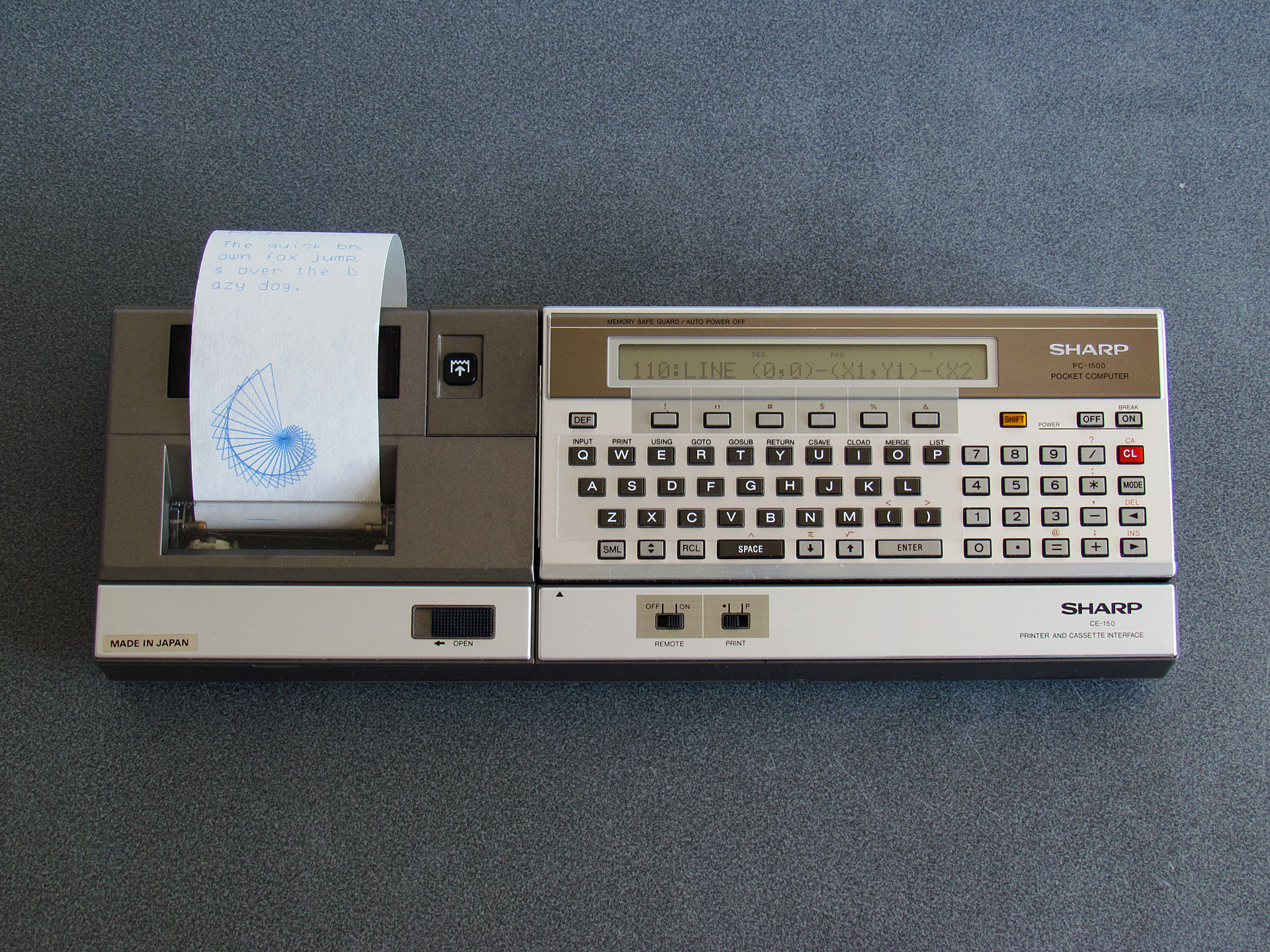
Sharp PC-1500 Pocket Computer connected to the CE-150 Printer and Cassette Interface
The Sharp PC-1500 is a small computer from the early 1980s that can run programs primarily written in BASIC. Programs can be saved to and loaded back from cassette tape but to do this requires it to be connected to the CE-150, a cassette interface that also includes a four-colour plotter. It's the plotter that really attracted me to the computer in the first place, but being able to load programs from cassette rather than having to type them in by hand is definitely a very handy feature!
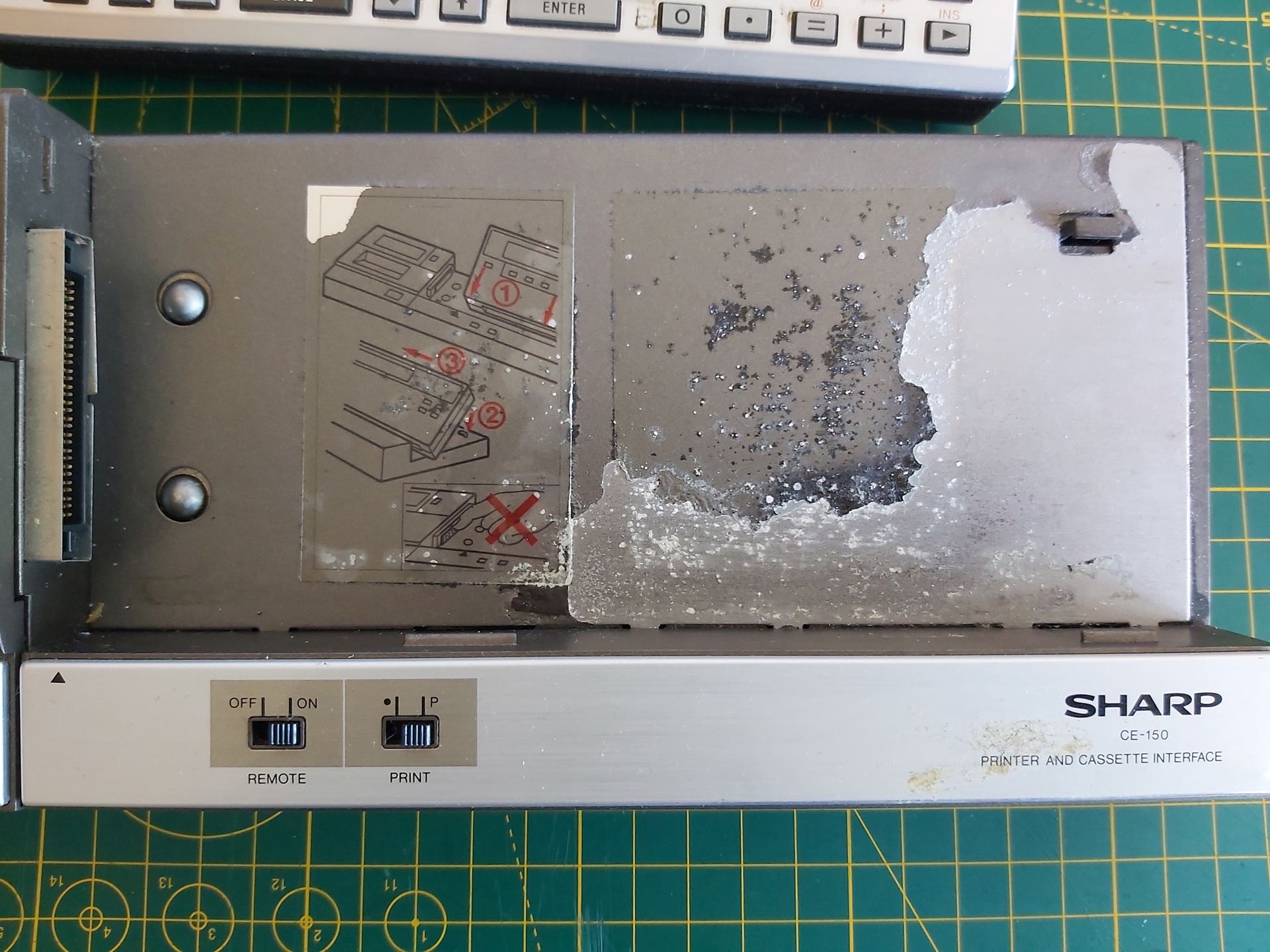
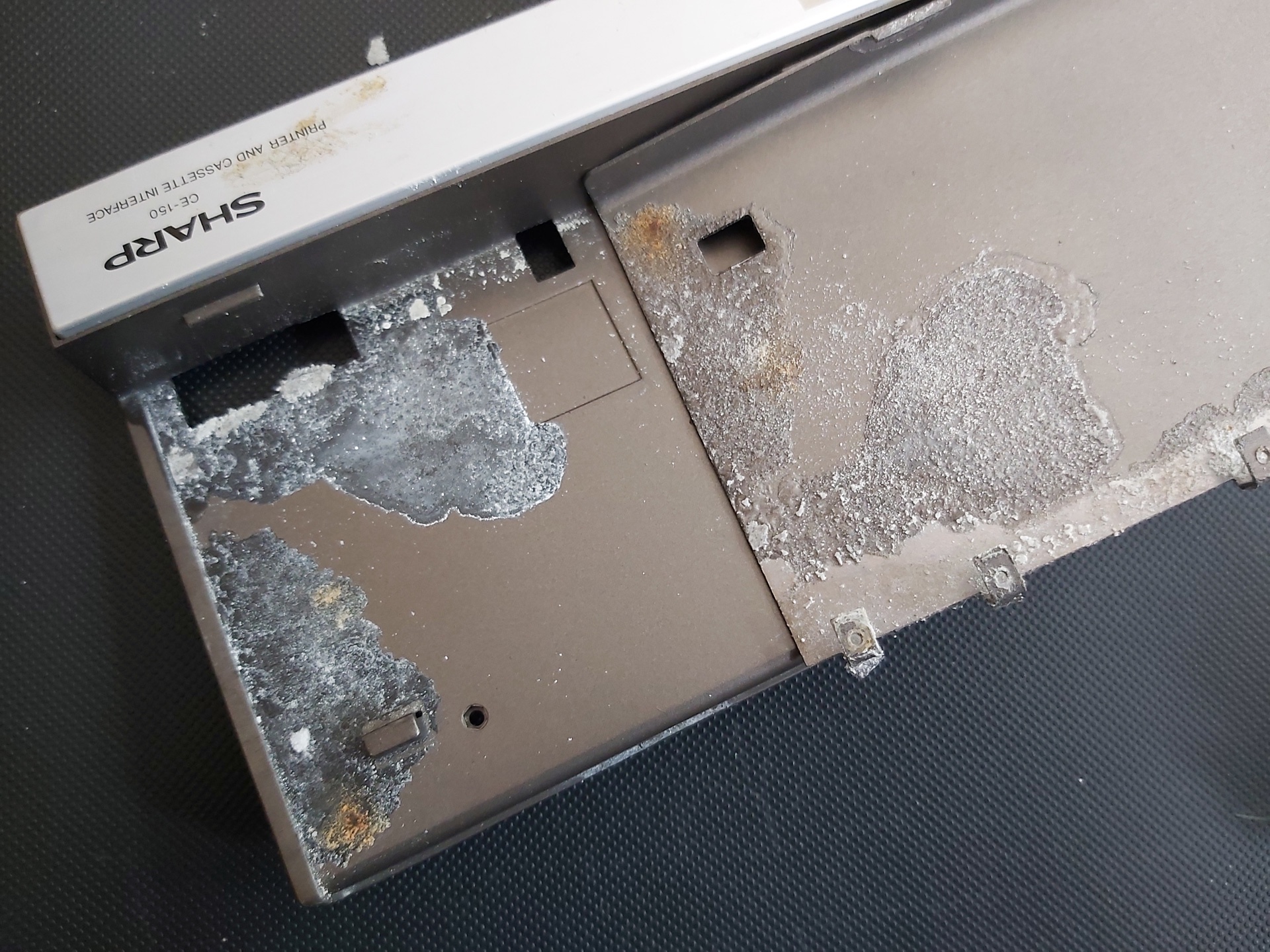
Unfortunately this CE-150 interface contains an internal battery pack of five Ni-Cd cells. A certain amount of battery leakage is a risk in any old piece of electronics hardware, but having said battery pack soldered directly in with no easy way for the user to remove it for long-term storage makes it more of a certainty than a risk. My CE-150 had not escaped, with heavy corrosion visible on the metal plate under the computer…
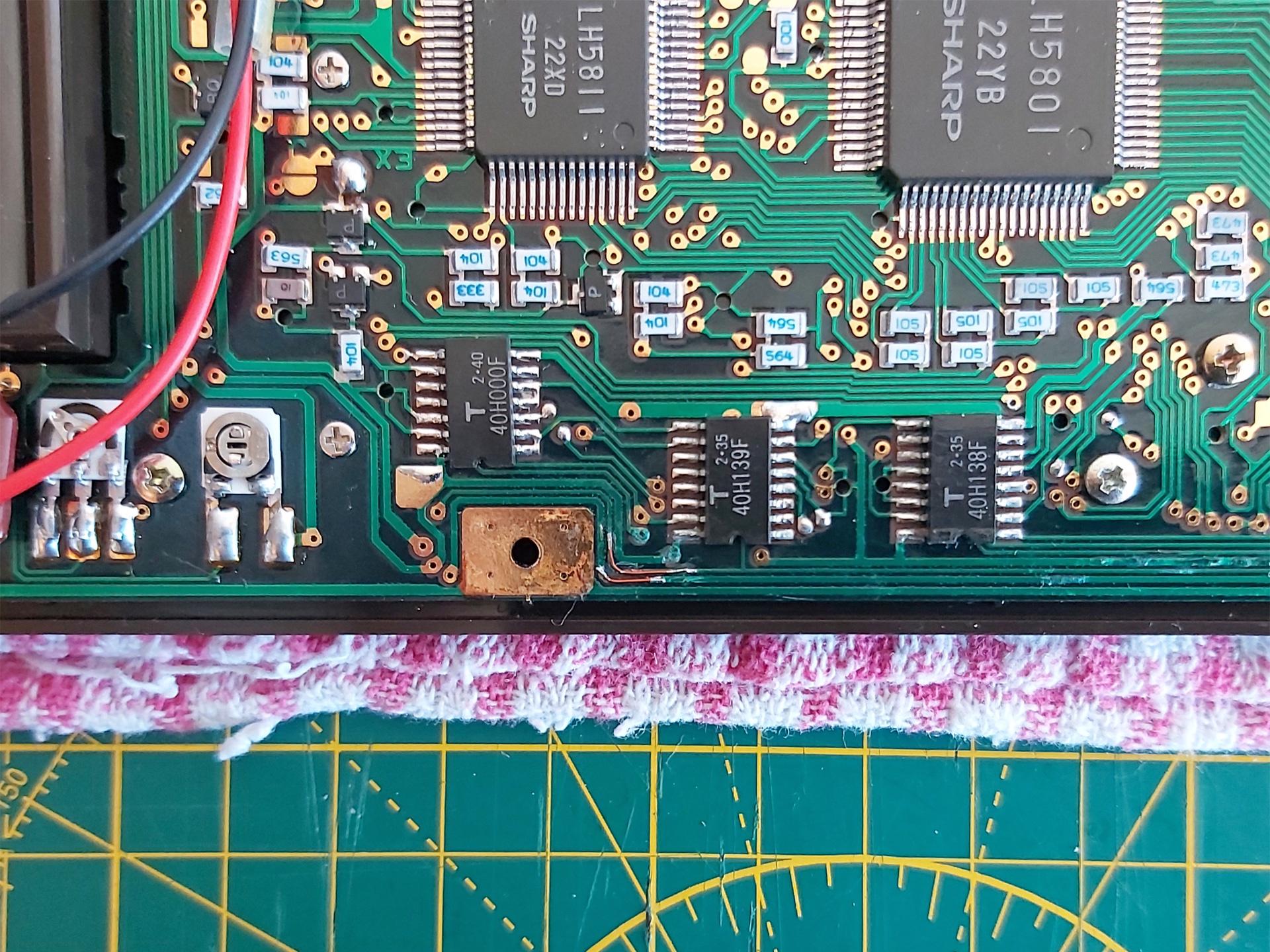
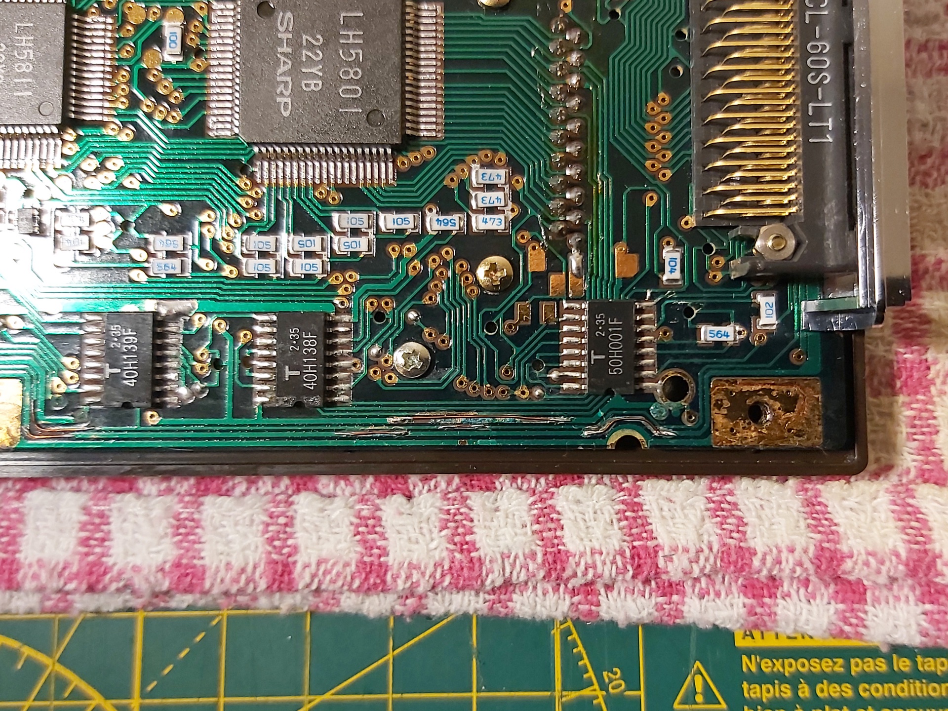
The inside of the PC-1500 was a bit better and not quite as musty-smelling, but circuit board traces had definitely been eaten away in places and some of the internal metal structure was looking a bit crusty.
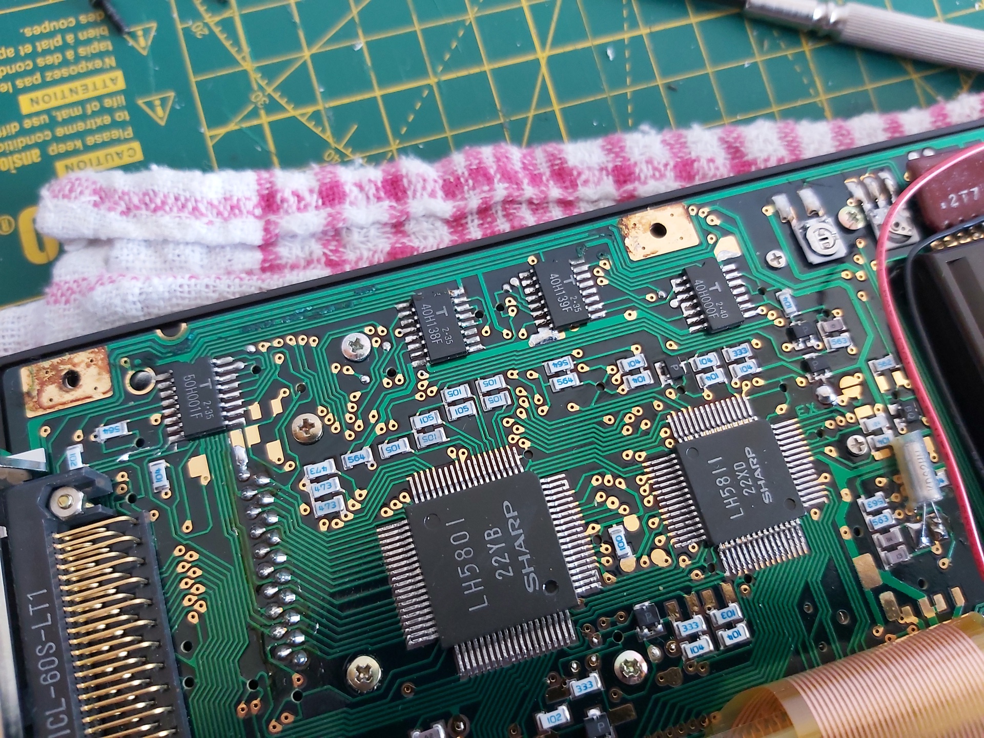
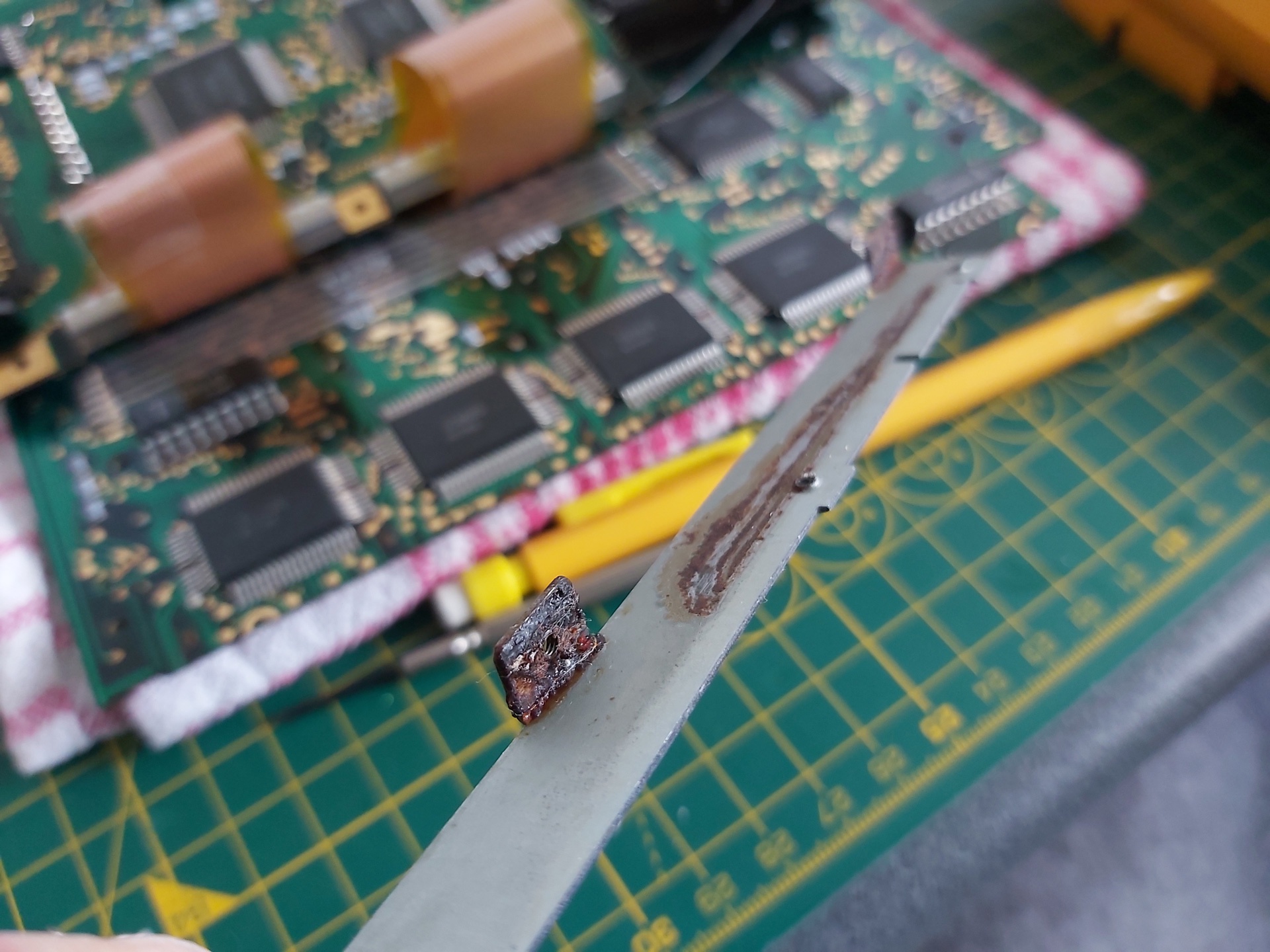
I cleaned up the rusty metal using some appliance descaler (and recorded a video of the process, which can be found on YouTube) then got to work with a scalpel and some fine enamelled copper wire to repair the damaged traces.
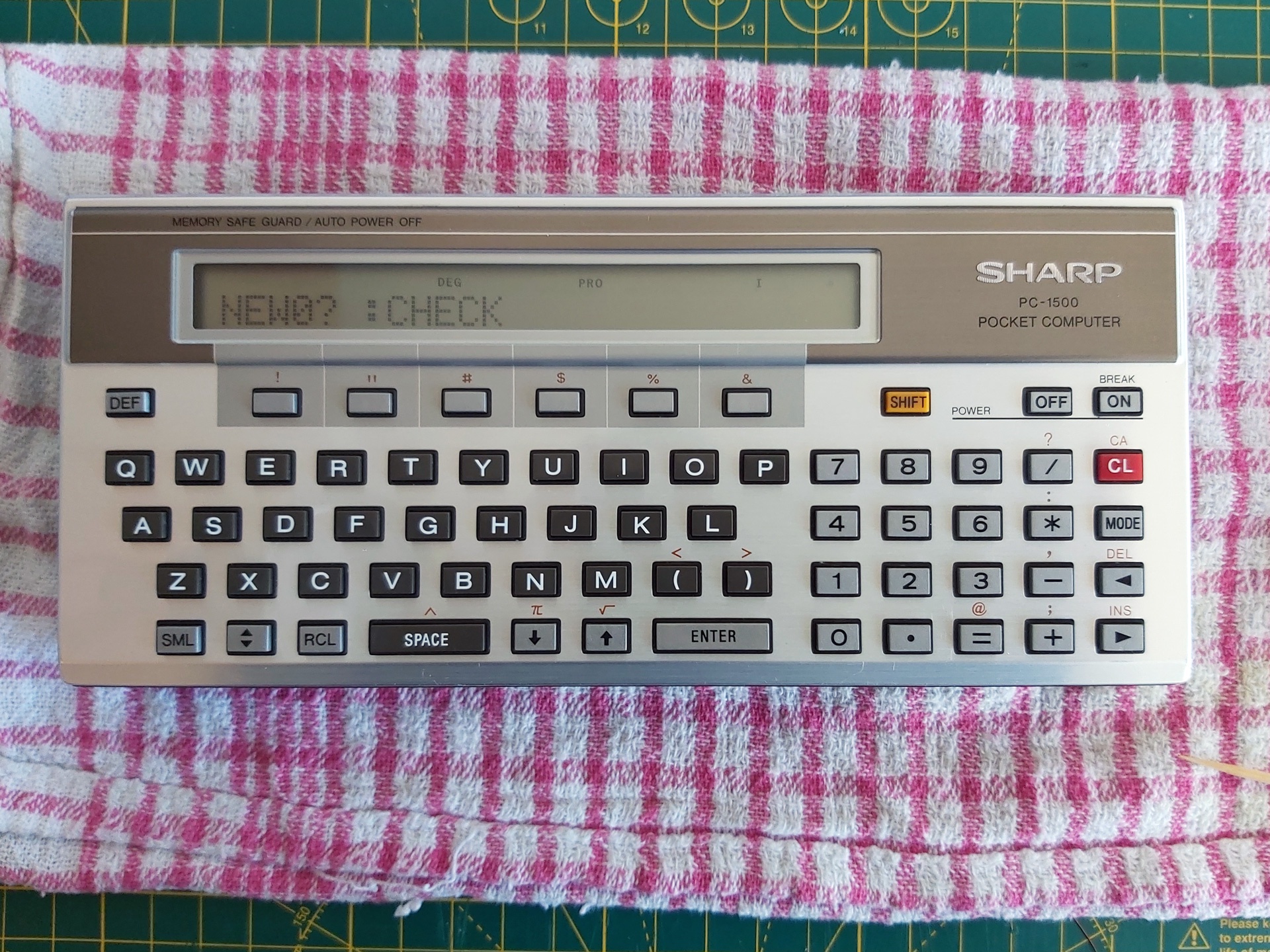
Thankfully when I put it all back together again I was greeted by the NEW0? :CHECK prompt, so I connected the computer to the CE-150 and confirmed I could save and load back programs using my PC in place of a cassette recorder. Hooray!
When looking to see what other people had managed to achieve with the computer I found the Sharp PC-1500 (TRS-80 PC-2) resource page which hosts several games and applications which can be downloaded in WAV format. I downloaded a few, but when playing them back on my PC the PC-1500 would refuse to load them. It could load from my own recordings, why not these?
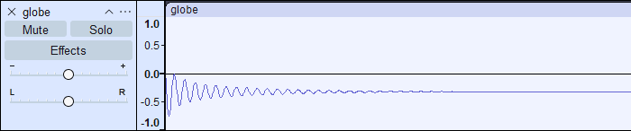
The odd thing is that my own recordings started with a few seconds of constant pilot tone followed by the varying pulses of the program data I was trying to load. When playing back the downloaded recordings they'd start with silence and only make sound when they got to the actual data – and that data sounded quite unlike what my own recordings sounded like. What was going on? I opened a recording in Audacity to see what it looked like, and zoomed in:
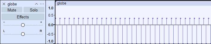
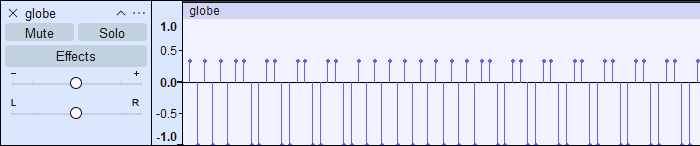
That looks like the pilot tone, in that it alternates between high and low at a fixed frequency, though it's only one sample high then one sample low so is a square wave rather than the smooth sine wave I was expecting. The cassette format uses frequency-shift keying so I would expect to see data further on in the recording at half the frequency, or twice the period, i.e. two samples high and then two samples low. Scrolling along, I certainly find that:
Why does it look so spiky, though? It would only need to look like that if it had been sampled at an extremely low rate, and indeed that's what I found – these files are recorded at a 5kHz sample rate:
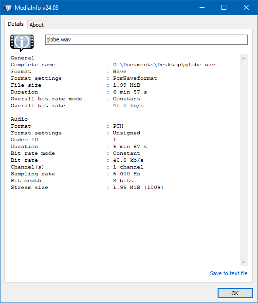
5kHz is a pretty unusual (and very low!) sample rate that I suspected my sound card was not handling particularly gracefully. Typically audio would need to be resampled to 44.1kHz or 48kHz before playing back, so I thought I'd try resampling in Audacity. This produced this weirdness:
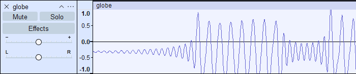
Instead of a sine wave that alternates between two frequencies, I ended up with something more akin to an amplitude-modulated signal! The high-frequency pilot also disappears entirely, apart from what looks to be some initial ringing:
Now, this is a complete guess, but I suspect that what is happening is an attempt to reduce unpleasant harmonics in the resampled audio. A square wave (such as the one we're resampling) produces a lot of harmonics at higher frequencies. As the original audio was sampled at 5kHz, the highest frequency that this could represent was 2.5kHz (alternating high and low each sample, as per the pilot tone). A low-pass filter at 2.5kHz could therefore reduce the harmonics, though I'd still expect some of it to get through (rather than it being apparently being attenuated to zero in this case!) In any case, the signal is being destroyed by the resampling process, so it's no wonder the computer can't load the data.
So, what's the solution? A simpler resampling algorithm that just duplicates samples (a sort of "nearest neighbour") should give us an acceptable square wave when processing, however I could not find any way to achieve this natively in Audacity. Fortunately, though, there's a Nyquist Plugin script that can be used to repeat all samples (install via Tools→Nyquish Plugin Installer, then check it's listed in Tools→Plugin Manager – it will appear as Effect→Repeat Samples). As we want to end up around 44.1kHz the plugin can be used to repeat each sample eight times, which would take our 5kHz sample rate to 40kHz:
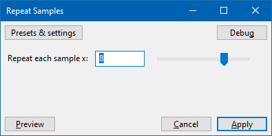
↓
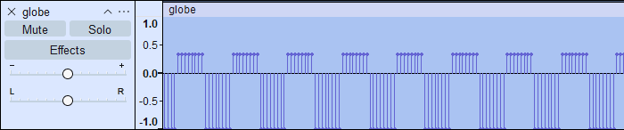
When played back the pilot tone can finally be heard, but it's at much too low a pitch! This is because the samples have been repeated eight times, but the track's sample rate hasn't been increased to match. This can be done by right-clicking the track and selecting Rate→Other and entering 40kHz:
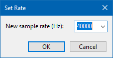
Now when the clip is played back it sounds as it should. As a further experiment, the sample rate could be changed from its somewhat odd 40kHz to a more conventional 44.1kHz via Tracks→Resample. When this is done, the nice clean square wave loses definition again:
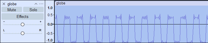
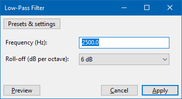
As I mentioned earlier, square waves have a lot of harmonics, and the resampling process makes these harmonics extremely visible riding on top and bottom of each cycle of the square wave. There is one way to clean this up quite nicely, however – as we want to cull high-frequency harmonics, and as the original recording could only represent frequencies up to 2.5kHz we can apply a low-pass filter at 2.5kHz from the Effects menu:
↓
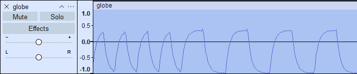
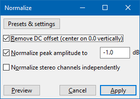
This resulting file sounds much better and loads into the computer as it should. It's a bit of a convoluted process, but it does at least bypass the resampling weirdness that distorts the original files in such a way that they can't be loaded. The only additional step I might recommend is to more neatly balance the signal around zero by normalising it as the first step:
In summary, the steps are as follows:
- Normalise the file (Effect→Normalize)
- Repeat all samples by 8× (Effect→Repeat Samples)
- Set track sample rate to 8× what it was (right-click, Rate→Other, multiply the value by 8)
- Resample to 44.1kHz (Tracks→Resample)
- Low-pass filter at 2.5kHz (Effect→Low-Pass Filter)
Happy tape loading!