Tape cycle frequencies and phases, plus VDrive3 support for BBC BASIC on the Sega Master System
Wednesday, 6th October 2021
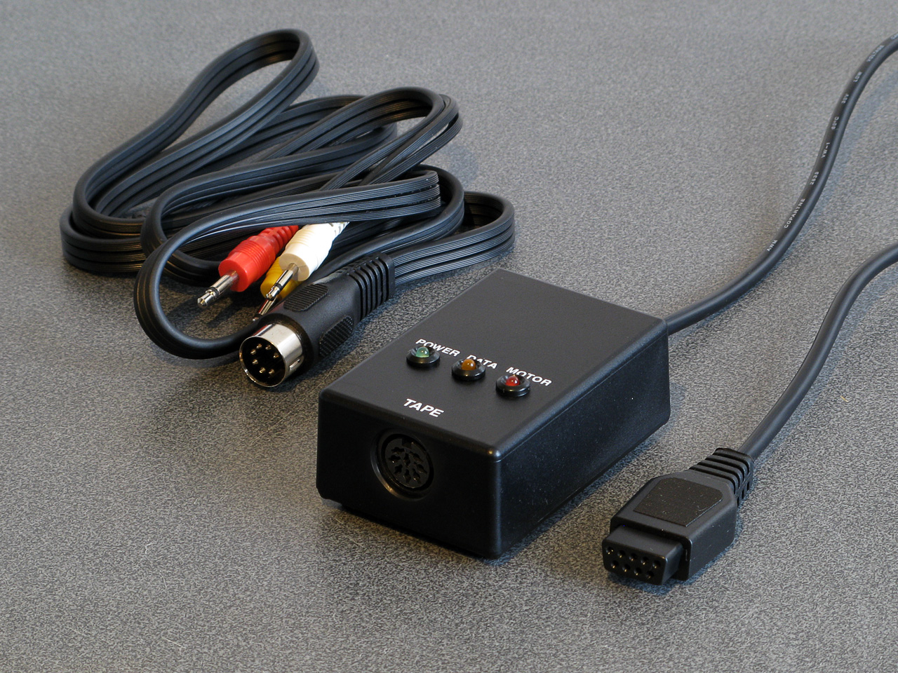
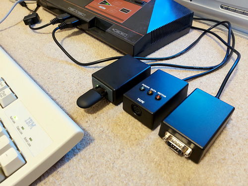
I have now moved the tape interface circuit described in the previous entry from its breadboard prototype to a neat enclosure where I am happy to report it mostly works as well as it did before.
I have spotted two issues, though. The first affects my small cassette recorder but not the large one, and is related to reading files from tape via the file IO routines (such as OPENIN then BGET# to retrieve a single byte, not from LOAD). Files are stored on tape in 256 byte blocks, and when the file is opened a whole 256 byte block is read from the tape and copied to the Master System's RAM. When the BASIC program requests a byte from the tape it is read from this local copy of the block instead, and when the read pointer reaches the end of the 256 byte block the next block is fetched from the tape and the local copy updated with this new data. The motor control comes in handy here, with the file system library stopping and starting the tape playback as desired.
The problem I was having was that the first block would read fine, but when the time came to read the second block the tape started playing but the file system library never seemed to be able to detect any data – it would just work its way along to the end of the tape, never displaying any errors, but never reading any meaningful data either.
The issue ended up being some code I'd added somewhat recently to automatically calibrate the threshold between a 1200Hz ("zero" bit) and a 2400Hz ("one" bit) tone. The code reads bits by counting the length of each wave cycle and comparing this to a threshold value - if it's longer, it's the 1200Hz "zero" bit tone, if it's shorter, it's the 2400Hz "one" bit tone. Before and after each file, and between each block, is a section of 2400Hz "carrier" tone. By detecting a large number of wave cycles that were all around the same length (say, within four length units of each other) you could assume that you were receiving the 2400Hz carrier tone and use that to calculate a suitable threshold for loading in data later.
The main bug was that I was comparing the length of the wave cycle just received with the length of the previous wave cycle rather than the length of the first wave cycle. This becomes a problem when you start a tape that was paused in the middle of a carrier tone (e.g. between blocks) as the tape will take some time to come up to speed, during which time the period of each wave cycle will gradually decrease. As the reference length we're checking the current wave length against is changing over time it means we end up compensating for the tape's speed increasing and so end up accepting the slower (longer) wave cycle lengths as part of the calculation of the threshold between "zero" and "one" bit wave cycle lengths.
As the wave cycle length threshold is now longer than it should be, all incoming wave cycles get interpreted as short ones and so it looks like we're just getting a stream of "one" bits - which looks like the carrier, so the code never starts trying to decode any blocks. My larger tape recorder comes up to speed much more quickly than the small one, or at least doesn't audibly ramp up in speed, and so isn't affected by this problem.
Fortunately the fix is very easy, just check the length of wave cycles against the first wave received rather than the previous one. This way if the timings drift over time (as they would during the period that the tape is coming up to speed) then they'll eventually go out of the permitted range. Changing this fixed the issue.
You may wonder why I'm calculating the threshold at runtime instead of just using a hard-coded value if the expected frequencies are a fixed 1200Hz and 2400Hz. My main intention was to be able to handle tapes that were running at the wrong speed due to a miscalibrated cassette recorder, but this does also open up the possibility to load from tapes at higher rates. Without any further adjustment my code can already load from audio generated at 2320 baud, i.e. with the two frequencies at 2320Hz and 4640Hz, without any further adjustment. This is a slightly annoying figure as 2400 baud would be the obvious target (being double the intended rate!) but at this speed the current code fails to latch on to the signal so I slowed the "tape" speed down until I found a value that worked. It's perhaps worth mentioning that the audio in this case was coming from PlayUEF running on my phone rather than an analogue cassette tape with the BAUD (or LOW) parameter used to adjust the speed, I'm not sure that a 93% boost in loading speed would be achievable from a tape!
I mentioned above that there were two issues. The slow speed-up issue affected the small cassette recorder, but the large cassette recorder had a new issue that only became apparerent after moving the circuit to its final enclosure. The Master System should be able to start and stop the cassette remotely, handled by a reed relay that is then plugged into the cassette recorder's "remote" socket. The Master System was able to start both tape recorders without any issues, but was unable to stop the large one – the "motor" status light would switch off, but the tape would continue playing. Tapping the relay sharply would be the only way to get it to switch off.
I tried plugging in a 2.5mm TS plug into the side of the large tape recorder and used the very scientific approach of shorting its connections with a screwdriver to simulate the relay switching "on" and was surprised to see quite large sparks. I measured the DC current through the remote control switch when the cassette was running and it was only around 70mA at its highest – well below the 1A rating of the relay – however I reckon there is a very large inrush current when the motor kicks in that is sufficient to weld the reed switch contacts together, causing it to get stuck.
Why didn't this affect the circuit on the breadboard? In that setup I was using a 3.5mm TS extension cable connected to a 3.5mm male-to-male adaptor cable which was then connected to a 3.5mm to a 2.5mm adaptor cable. My assumption is that all of the extra contact resistances were helping to limit the inrush current, preventing the contacts from welding together.
It's very likely not the best sort of snubber circuit for this application but for the time being I've put a 10Ω resistor in series with the relay contacts, which limits the inrush current enough for the relay not to get stuck:
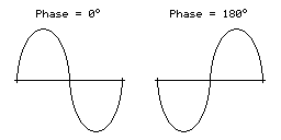
One matter that I've also been testing is the phase of the audio signal. As far as I can tell Acorn's tape format assumes a 180° phase; that is to say that each wave cycle starts at 180° and runs to 180°+360°=540° for a complete cycle rather than starting at 0° and running to 360°. The result of this is that instead of the signal starting at an amplitude of 0, then going positive before negative (as you'd expect for a typical sine wave) the signal goes negative first:
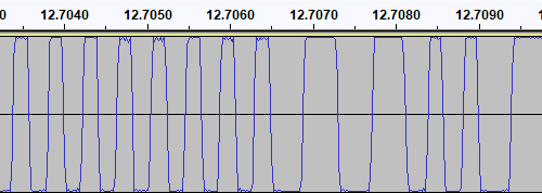
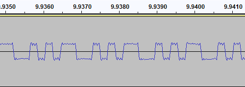
I have confirmed this by looking at the output of tools like PlayUEF as well as looking at the signals coming directly off commercially pre-recorded tapes with BBC Micro software on them, after first confirming that my sound card doesn't invert the signal by briefly connecting its input to a positive DC power supply and seeing that the received signal goes positive when that happens. Here's an example of a commercially-released tape, where you can see that after the high-frequency cycles in the first longer wave (a "zero" bit, acting as the start bit, starting at around 12.7065) starts low then goes high:
I then generated a test tone that alternates between 0 and 1 bits, i.e. one complete 1200Hz cycle then two complete 2400Hz cycles with the appropriate 180° phase:
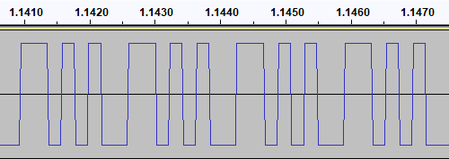
This pattern should make it easy to spot the phase of recordings. I first tried running the test tone straight back into my PC to ensure that the phase was not being reversed by the PC, and got the same signal back in compared to to what I played out, as you'd expect. I then tried recording the signal to tape with my Grundig recorder, and found something interesting when playing it back:
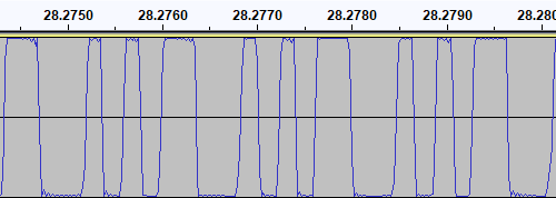
The phase there is very clearly reversed – the signal I played into the tape recorder goes low before it goes high, whereas the signal I've recovered goes high before it goes low. I repeated the test with the Alba tape recorder:
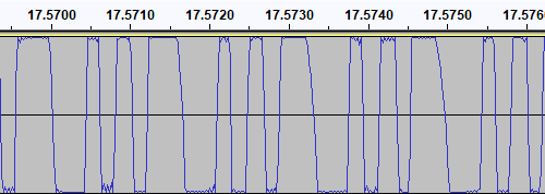
This shows the same thing – the phase on the tape is at 0° even though the test signal was at 180°. I also have a Sony digital voice recorder (an ICD-BX140) that I've been using as well as a tape recorder, so I tried the test with that too:
Apart from the much lower recording level this once again shows the same thing – the signal phase is inverted when recorded.
I had previously encountered an issue where I had tried to make a tape from a UEF image by playing the audio generated by PlayUEF into a tape recorder. Attempting to load the data directly from PlayUEF worked fine, but the tape recording of the same signal wouldn't load. My Grundig tape recorder has a phase reversal switch, and setting it to "reverse" would allow me to load the tape created by recording the output of PlayUEF. However, in that reverse setting, I lost the ability to load from my commercially-recorded tapes. I think the above tests indicate why this is the case – the recorders all invert the signal when creating the tape recording. I find it particularly interesting that the Sony digital voice recorder does the same thing!
I did check to see if the phase switch on the Grundig tape recorder had any influence on the recording, but it doesn't – whether it's set to "normal" or "reverse" the recording to tape still ends up inverted. The phase switch only appears to affect playback.
PlayUEF does have an option to set the output phase to 0° instead of its default 180°. By doing that and recording its output to tape I was able to load the programs directly from either of my tape recorders.
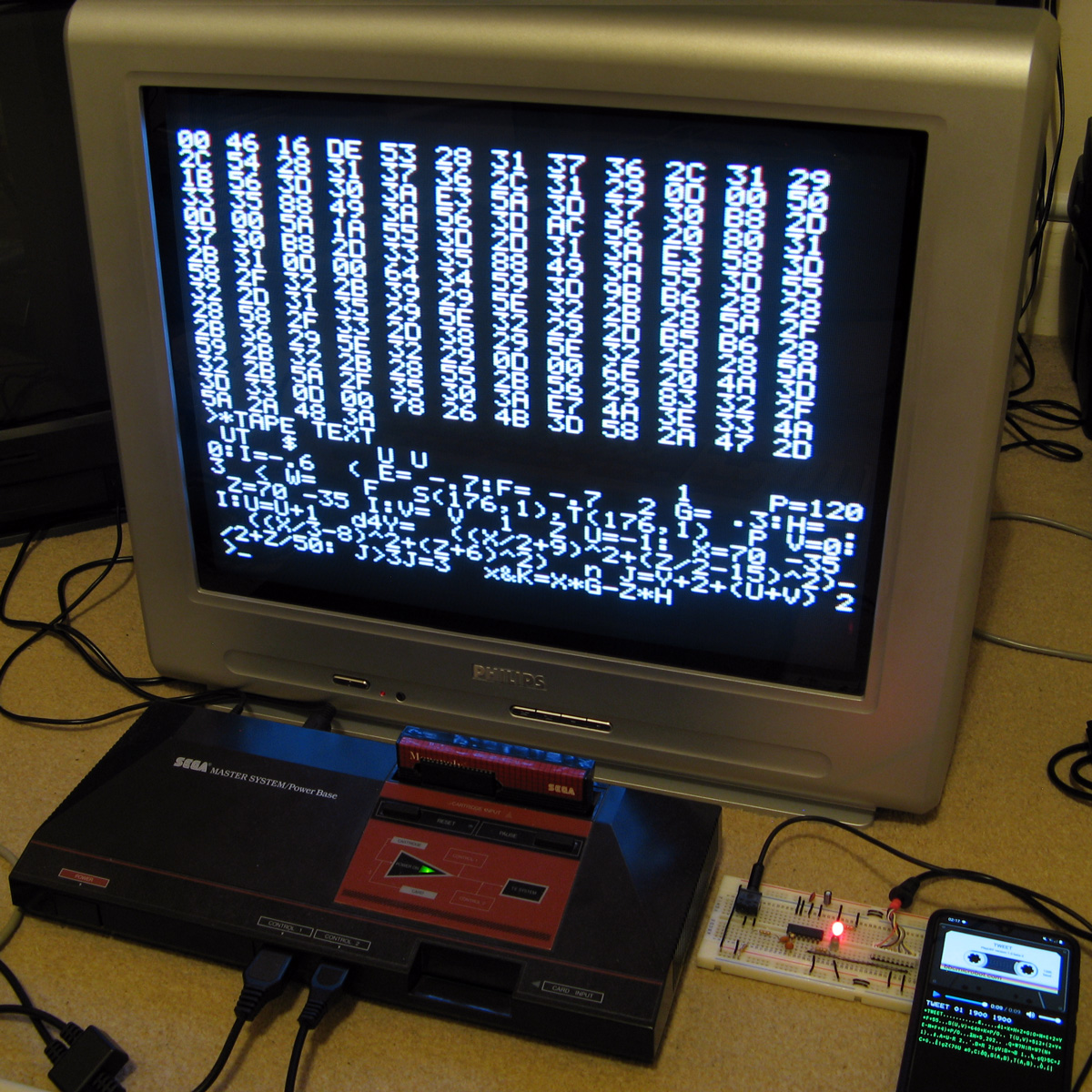
Of course, it would be nice if the loader was able to handle either phase, and in practice I've found it does sometimes handle the "incorrect" phase quite well but it does seem to be more a lot more error prone – some programs load without any problem, others report problems with some blocks and others fail to be detected at all! I think I'll see if there's a way to reliably detect the phase and switch to the appropriate handler, but for the time being I've added a crude workaround – pulling pin 1 of the controller port (the d-pad "Up" input) to ground tells the loader to assume the phase is inverted. As I hope this won't be necessary in future I've left this as a jumper in my current tape interface circuit (visible below in the top left corner) rather than add a switch!
A lot of the work has been focused on the tape loader, but tapes are not the most practical storage media these days. Finding a working tape recorder is a challenge in its own right, and a lot of the old tapes are tricky to work with as they've become sticky with age. In an attempt to be a bit more modern I've started integrating support for the VDrive3 to BBC BASIC. This is an inexpensive module that lets you access files on a USB mass storage device via simple commands sent over a serial interface. I'd previously used the VMusic2 device in another project and that uses the same firmware commands so I already had a little experience with it (the VMusic is pretty much a VDrive with an MP3 decoder bolted on top). I already had some serial routines written so it was a reasonably easy job to plumb in some code to handle LOADing and SAVEing programs, and from a hardware perspective all you need is a cable to connect the module directly to the Master System's controller port – the VDrive3 uses 3.3V signalling levels but its I/O lines are 5V tolerant.
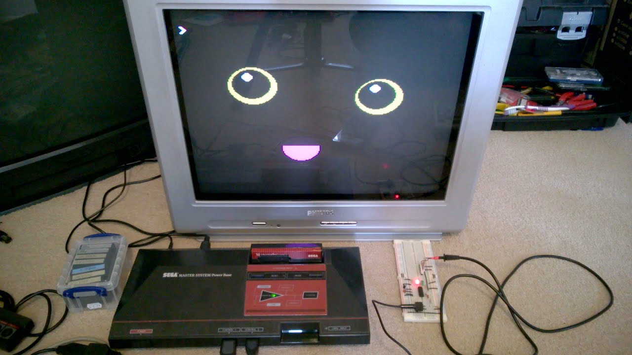
One notable advantage of the VDrive3 over the tape interface is that it allows for proper random-access of files rather than just sequential access. I've been working on implementing all of the required BASIC statements to support this (OPENIN, OPENOUT, OPENUP, BGET#, BPUT#, PTR#, EXT#, EOF#, CLOSE# etc). For a bit of fun I wrote a BASIC program that loads an image file from disk (or tape) and displays it on screen. I needed to add user-defined character support to the new reduced-resolution MODE 2 to handle this (something that was not implemented before due to a lack of VRAM) but with that in place it's working pretty well.
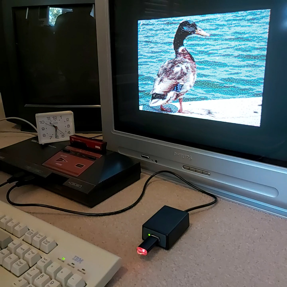
It's not fast, taking 2m45s to load from from tape and 1m19s from a USB flash drive, but it's a fun diversion!
Refining the tape interface for BBC BASIC on the Sega Master System
Tuesday, 28th September 2021
It's been quite a while since my last post but work has continued with the version of BBC BASIC (Z80) for the Sega Master System. Most of the features I have been working have not been particularly exciting to write about on their own, but here are some of the notable changes:
- All VDU code (for text and graphics output) has been moved to a separate ROM bank, freeing up around 16KB of extra ROM space. It makes calling the code slightly more complicated but in the previous post I mentioned that I had less than 100 bytes of free ROM space so this was definitely required.
- Simplified the video mode driver interface. Each video mode has its own driver code which exposes a number of different functions. Previously, each function had its own vector in RAM which was fast but consumed a lot of precious work RAM. Now only a couple of functions (which need to be called frequently and as quickly as possible) are vectored, and all of the other functions are called via a single generic function with a parameter for which specific operation to carry out (e.g. "reset the graphics viewport", "change the text colour").
- Rewrote the triangle filling routine and line drawing routine to ensure that the same pixels are covered whether you fill a triangle or trace its outline – previously there would be some stray pixels that leaked outside the perimeter of a filled triangle.
- Changed the output resolution for most video modes to 240×192 with a logical to physical pixel scale factor of 5⅓ for a total logical resolution of 1280×1024, the same as the BBC Micro – graphics programs designed for the BBC Micro now properly fit on the screen.
- Changed MODE 2 to use a smaller resolution of 160×128 with a pixel scale factor of 8. Unfortunately, there is not enough video RAM to have a unique pattern in VRAM for every character position on-screen when using all 16 colours (as in mode 2) at the higher 240×192 resolution. The new lower resolution avoids screen corruption that previously occurred when running out of VRAM:


MODE 2 graphics at the full-screen 240×192 and reduced 160×128 resolutions
- Added support for scrolling the text viewport down as well as up, this is used by the line editor which now allows very long lines to be edited in small viewports by scrolling and repainting as necessary.
- Reworked the keyboard input routines for greater reliability and performance, including proper mapping of key codes in *FX 4,1 and *FX 4,2 and removal of "clever" (but flawed) interrupt-based detection of when a key is available (that had a habit of dropping keys and resulted in worse performance than just periodically polling the keyboard anyway).
The most significant changes have been all to do with loading and saving from tape, though. Since my previous post I have been doing a lot of work testing and refining both the hardware and software of the tape cassette interface. The hardware has now been tested with a couple of different tape recorders, as well as a pocket digital recorder, my mobile phone and my PC's sound card. The loader is much more robust and if a single block fails to load from the tape you can usually just rewind the tape a short way and it will try again, no need to rewind back to the start and start from scratch. I was previously counting the duration of half-wave cycles from the tape and comparing these to some fixed thresholds baked into the code to determine the difference between a "0" and a "1", I've now changed this to measure full-wave cycles (which aren't affected by any duty-cycle shifts in the recordings) and to calibrate the thresholds during the initial carrier tone, which allows the code to compensate for tape recorders that aren't quite running at the correct speed. On a more practical basis I've also added the ability to save to tape, motor control via a reed relay (so the tape will automatically stop after a file is loaded), and support for opening files on tape for reading or writing and accessing them on a byte-by-byte basis. As tapes are sequential access there are some limitations to this (for example, you can only advance the read pointer later in the file, you can't seek backwards) but it works quite well otherwise.
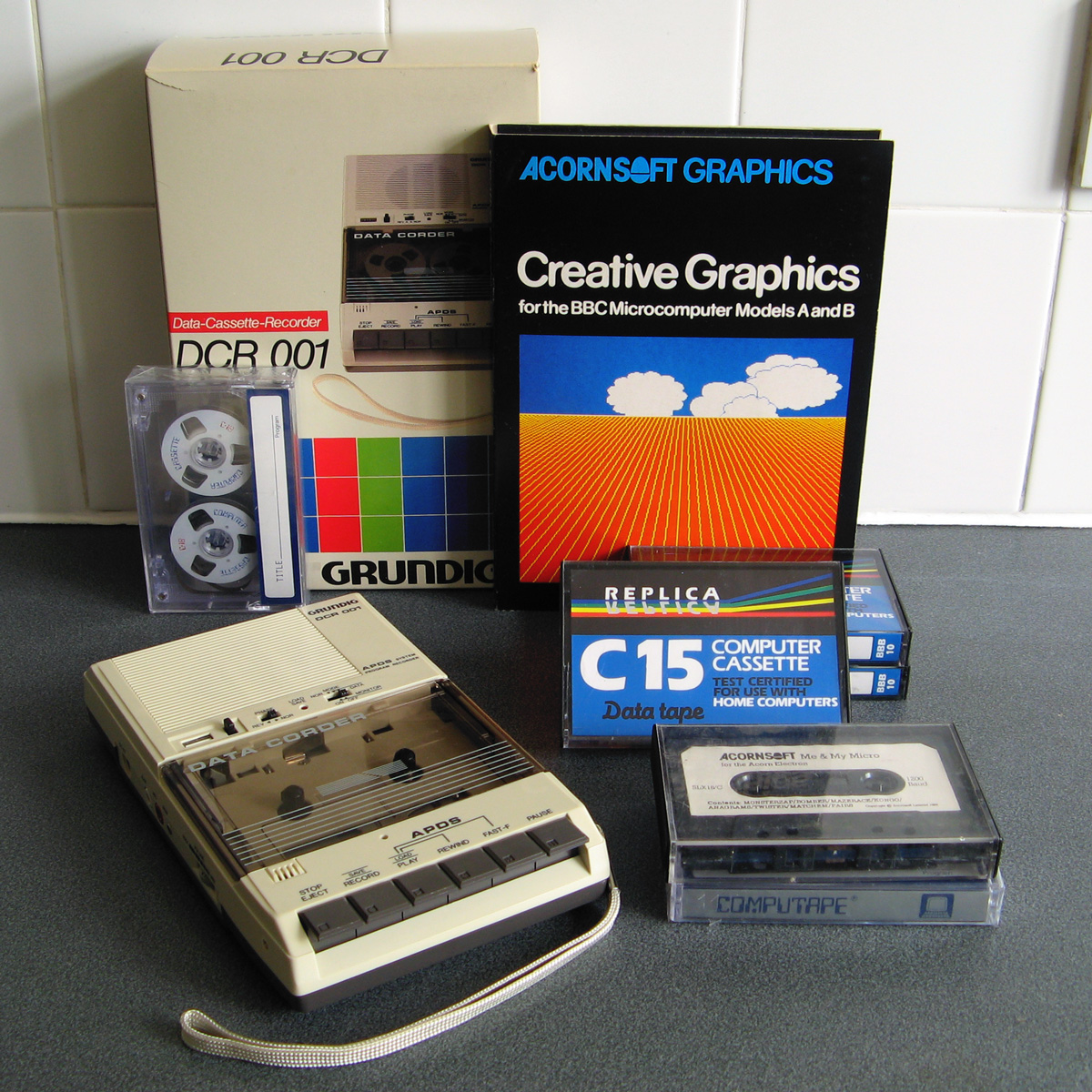
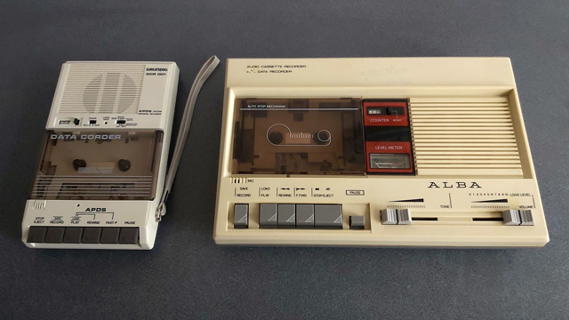
Of course, to test all of this I needed a tape recorder! I purchased the above Grundig DCR 001 data cassette recorder as well as some blank cassettes and a couple of commercially-prerecorded ones to do so. The DCR 001 has a few nice features that make it great for loading programs:
- A dedicated "data" mode that sets the output level at an appropriate fixed level – no need to guess about finding a suitable volume level.
- An optional "monitor" in data mode that lets you listen to the data on the tape as it's loading.
- A "phase" switch that can be used to reverse the phase output, to compensate for the case where the data has been recorded with a 180° phase shift.
- An "Automatic Programme Detecting System" that lets you skip ahead to the next program or back to the previous one by pressing Rewind or Fast Forward when Play is pressed – this stops when it detects a silent gap between recorded sections of data on the tape.
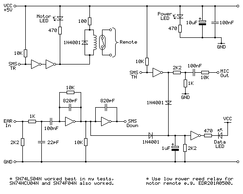
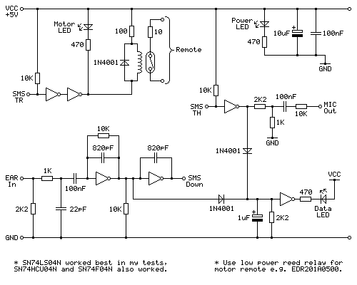
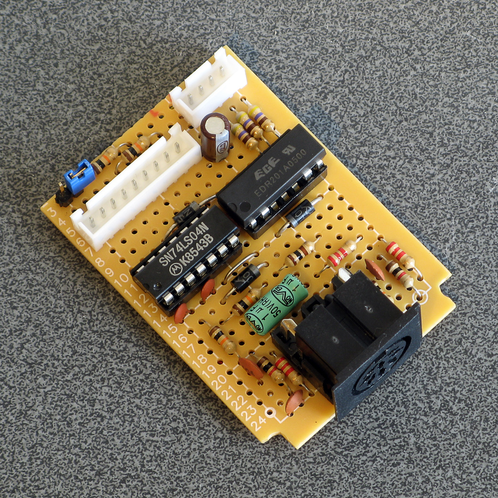
Above is the cassette interface circuit I came up with. It's quite simple and has a notable lack of analogue sections (no op-amp chips here!) – it uses a NOT gate with a 10KΩ negative feedback resistor to turn the analogue signal from the tape recorder's earphone output into a clean digital signal that can be fed into the Sega Master System. I've tested this with an SN74LS04N, SN74HCU04N and SN74F04N and all worked well, however for best results I'd recommend the SN74LS04N. The filtering capacitors clean up some high-frequency pulses/glitches that may otherwise end up on the output; this is not something I found was much of a problem with a cassette recorder or the audio output from my phone or PC, but a pocket digital voice recorder I have seems to produce glitchy high-frequency pulses in its output (I'm not sure if that's an artefact of its DAC or in the MP3 compression it uses for its voice clips) and those capacitors clean up the signal enough to be able to read it reliably.
The remote motor control relay is a reed relay, and must be a low current device to avoid overloading the Master System's controller power supply and to also allow it to be driven directly by the hex inverter chip. I found the EDR201A0500 perfect for this role!
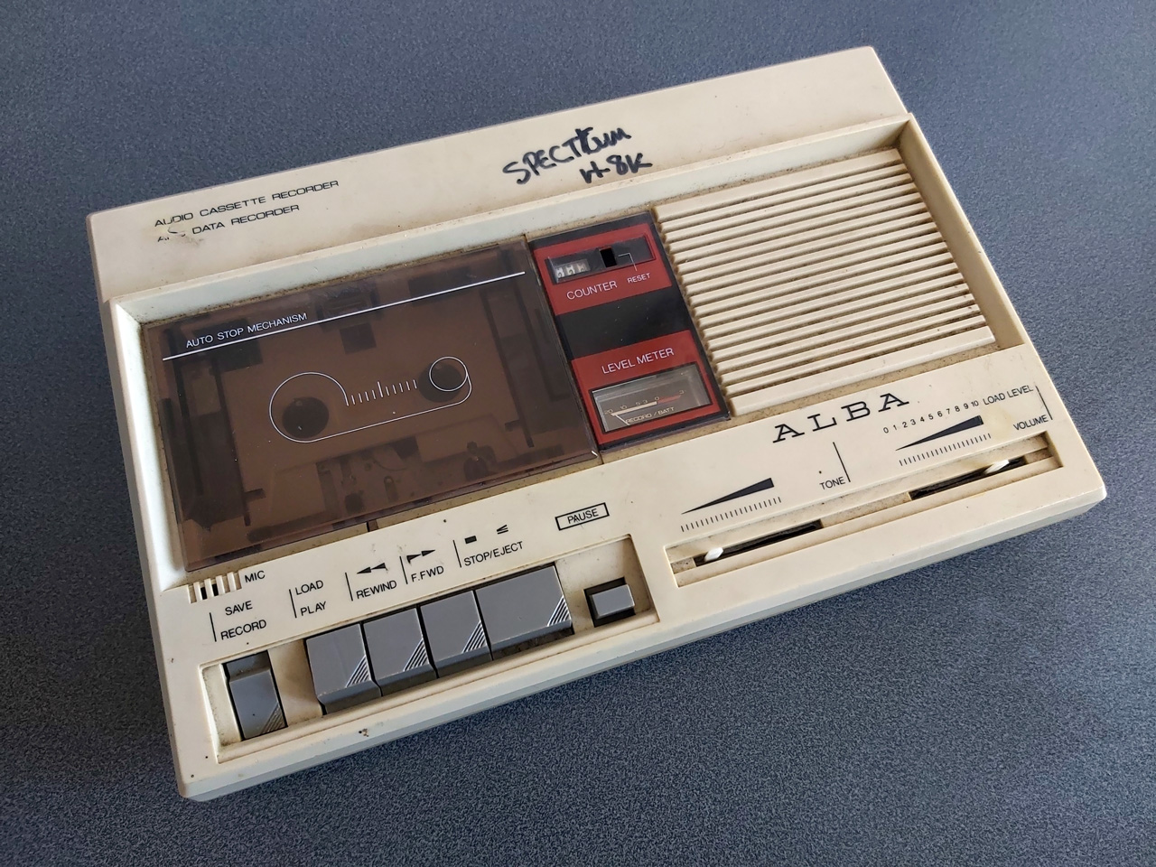
Being able to save and load back programs on one cassette recorder is fair enough, but to really be sure my hardware and software are working as they should I thought I should see if I was able to save a program to tape on one tape recorder and then load the same program back on a different tape recorder. To this end I bought the above cassette recorder. It was clear from the listing that the record button and counter reset button were damaged, and the whole thing was quite grubby, but I thought it worth a punt.
Getting inside was very easy as all but one of the screws was missing, and it was clear that someone had got there before me as the damaged plastic parts (including two of the main screw posts as well as the snapped-off parts of the record button and counter reset mechanism) had been removed at some point. After giving the tape path a very thorough clean and replacing one of the drive belts that was turning into a tarry mess I was able to get it to play a tape, so I took everything out of the enclosure to give that a good scrub and prepared to fix the damaged plastic parts.
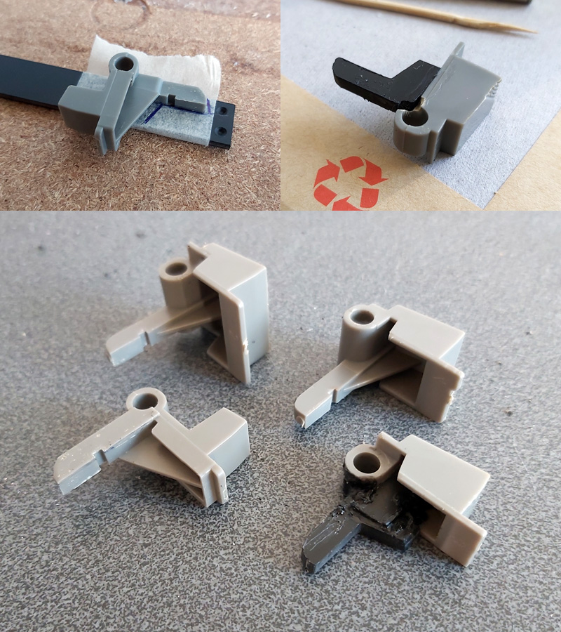
By tracing the arm from one of the other buttons onto a piece of scrap ABS plastic I was able to make a replacement arm for the damaged record button, which I then glued on with cyanoacrylate and some two-part epoxy resin to fill in the gaps. The result is not especially pretty but it does the job and my blobby repair is not going to be visible unless you take the recorder apart.
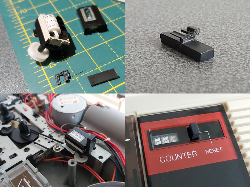
The counter reset button was a bit more fiddly; the reset mechanism seems to rely on the "n" shaped bit of plastic shown above in the top left photo, and though it looked like something used to be attached to it that had snapped off I wasn't sure what it would have originally looked like. I cut up some more scraps of ABS sheet to make up a new counter reset button which seems to work pretty well, though!

The final addition was a couple of new knobs for the tone and volume sliders – these are cheap generic parts and they don't quite line up with the markings (the original sliders have off-centre indicators) but overall I think this turned out pretty well, and my main concern – being able to save a program to tape on one machine and then load it back from another – has been thoroughly tested now and I'm happy with the results. My next task is to transplant the circuit from its current breadboard layout to a neat project box!
Loading BASIC programs from cassette tape to the Sega Master System
Monday, 16th August 2021
After I posted about the pattern filling modes on Twitter I was alerted to the BBC Micro Bot website which hosts a gallery of programs that produce impressive graphical output from very short BASIC programs (short enough to fit in a Tweet!)
I tried a few of them out but unfortunately ran into problems with a lot of them that use various tricks to reduce the original program text length by embedding non-ASCII characters directly into the body of the program. My usual approach to prepare programs was either to copy and paste them into an emulator (my emulator strips out non-ASCII characters on pasting, as these can't be mapped to keystrokes) or to save them to a file and transfer that serially, and my own editor's tokeniser and BBC BASIC for Windows both had a habit of mangling the non-ASCII characters.
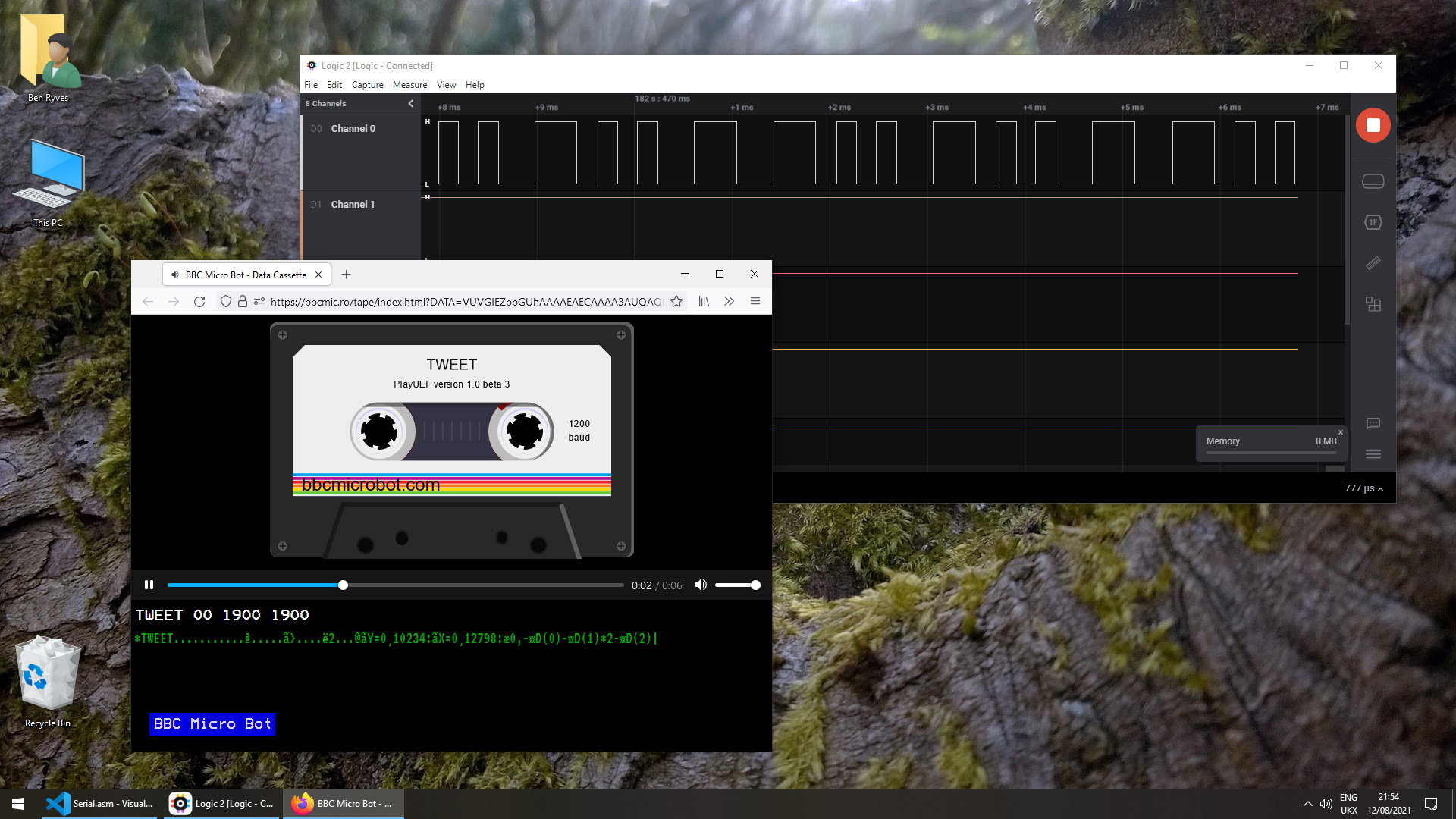
The BBC Micro Bot website does not provide a way to download the BASIC programs directly but does provide a share link that allows you to export a disk image or play back the program from a virtual tape cassette. I don't have a a disk drive attached to my Master System, but the tape option seemed promising...
The basic cassette tape interface
My initial approach to loading programs into BASIC from external storage was to connect my Cambridge Z88 computer running PC Link 2 or EazyLink to the Master System with an RS-232 serial cable. This works well for me, but isn't very practical for others who might not already own a Z88, and I do want this to be an easy project for people to replicate!
Being able to load from tape would significantly lower the barrier to entry, if the cassette tape interface circuit can be constructed easily. You wouldn't even need an actual tape player; the drive belts have gone in mine (I tried to make a test recording on mine and it just unspooled the tape into the bowels of the machine) so for the time being I've been testing loading from PlayUEF, the web-based UEF player that's also found on the BBC Micro Bot website. This can be run from a browser and it works well on my mobile phone and makes loading programs from a web link an absolute doddle. Perfect!
The challenge, then, is how to get that audio data into the Master System in the first place and whether it's got enough grunt to be able to decode it in software. Using the same tape format as the BBC Micro seemed like it would be a good choice so I read this article on the Acorn cassette format on BeebWiki. The highest frequency audio signal is a sine wave at 2400Hz. As we'll need to handle both halves of each cycle we'll need to sample the signal at least 4800 times per second. As the Master System has a CPU clock of around 3.58MHz, that gives us 3.58×10⁶/4800≈756 CPU cycles for each half of the cycle which should be more than sufficient.
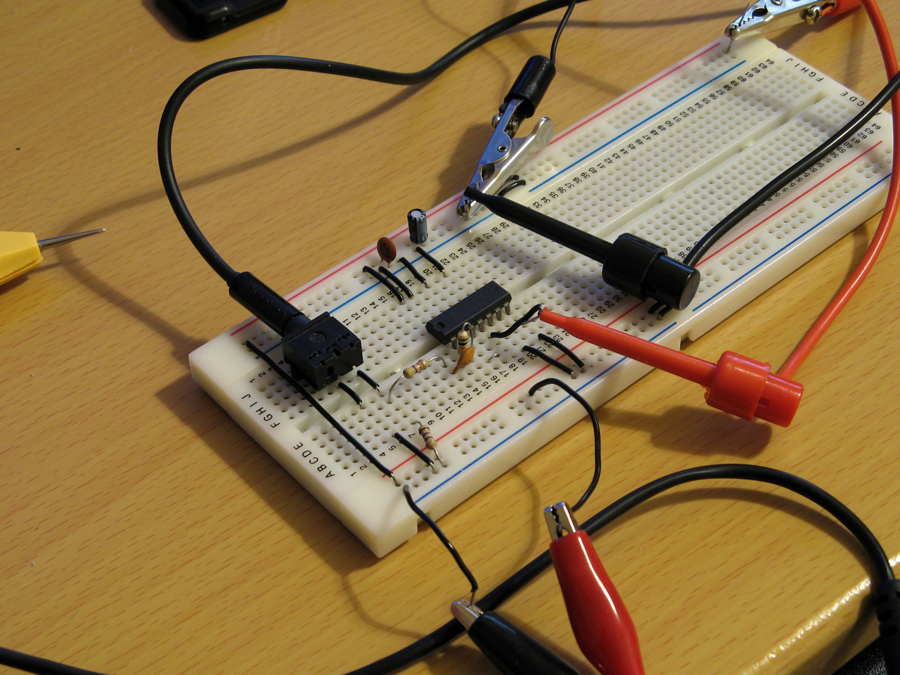
We still need to get the audio signal into the Master System somehow! I did a bit of digging online and couldn't find too much information about suitable electrical interfaces. My best lead was the circuit diagram for the BBC Micro's tape interface, however that requires several op-amps and I only have a single LM741 in my parts bin, which isn't going to do a very good job on a single 5V supply. In the short term I've used the circuit above which is a slightly modified version of this common circuit used to convert S/PDIF signals to TTL levels using an unbuffered hex inverter as an amplifier. It's not the most stable circuit and has a habit of oscillating when not fed an input signal but the +5V pullup on the output from the console inhibits this (putting a pull-up or pull-down on any of the inputs changes the mark:space ratio of the pulses). That a load on the output affects what's happening on the input is definitely not a good indication of a properly-functioning circuit, but it'll have to do for now.
I don't know how well it'll respond to a real tape cassette player, but the signal from my PC's sound card or my mobile phone produces very clean square pulses so it should be enough to start experimenting with until I can come up with more stable design.
Decoding the tape signal in software
To decode the signal we'll need to know whether the tape is outputting silence, a 1200Hz tone or a 2400Hz tone. I'm handling this with a simple routine that samples the current level of the input, then loops around waiting for the input level to change state, counting the number of times it takes to go around the loop before the transition. If the counter overflows before the state changes then it's assumed that the tape is outputting silence, but if the state changes before that we can check the value the counter reached to see if it got to a small value (a high frequency signal from the tape) or a large value (a low frequency signal from the tape).
To determine a suitable value for the thresholds I wrote a test program that simply called this routine in a loop 256 times, storing its results in memory, before dumping the results to the screen once all 256 values had been found. By playing a section of the tape in the middle of a data block (so there would be a good mixture of 1200Hz and 2400Hz tones) I got the rather pleasing result that 1200Hz tones appeared to make the counter reach $20 (32) and 1200Hz tones made the counter reach $10 (16), so I put the threshold value between them at 24 as an initial test.
Once we know the frequency of the tape signal at a particular point we can use this to determine the current bit – a "0" bit is a complete 1200Hz cycle (so we'd see two instances of the counter reaching >16) and a "1" bit is two compete 2400Hz cycles (so we'd see four instances of the counter <16). Knowing the bit on its own is not very useful, though, so I added byte decoding which waits for a start bit (0), receives and stores 8 data bits, then checks for a stop bit (1). I could then dump this data to the screen:
At this point the data isn't completely correctly decoded, but it always produces the same results on every run-through which to my mind was a good sign. The text displayed at the bottom of the screen shows some recognisable fragments of the original BASIC program (as the program is tokenised the keywords are missing). The main problem I was having was down to synchronisation; as the article on BeebWiki states "an odd number of 2400Hz cycles can and does occur" and these occasional cycles were throwing me out of sync. The fix was to add an extra check when handling 2400Hz; even though four 2400Hz half-waves are expected, if a 1200Hz half-wave is detected instead it's assumed that we've gone out of sync and the bit should be decoded as a complete 1200Hz pulse instead. After making this change more recognisable text started coming through, so I was able to move on to decoding the data blocks.
Decoding data blocks on tape
Files on tape are broken up into multiple data blocks, each with a header describing the block (e.g. file name, block number, data length) followed by a variable amount of data (up to 256 bytes) containing the data itself. To load a file from tape each incoming block has to be handled. If the block number is 0 then that's the start of the file, so the filename is checked. If this matches the supplied filename (or the supplied filename was the empty string "") then the loader switches from "Searching" to "Loading" mode and the data we just received is stored in memory. From that point on each incoming block is appended, as long as the block name and number match what we expect (i.e. the same filename as before but the block number should be the previous block number + 1). This continues until the "end of file" block flag is set. A CRC-16 of the received data is also checked after each block to ensure that the data has been received successfully. If there are any errors (the block name/number doesn't match what was expected, or the CRC-16 check fails) then an error message is printed and you can rewind the tape a bit to try receiving the block again.
This doesn't sound too complicated, but I've not had too much luck implementing this successfully. My code is currently a bit of a mess and doesn't properly maintain the "Loading" or "Searching" states which means that if an error occurs at any point then it can get a bit confused trying to resolve it (to the point where it's easier to just abort the load and start again from the beginning). However, the tape block issues are not the only problem...
Conflicting BASIC program formats
The programs I'm trying to load are designed for the BBC Micro, where programs are stored in the Acorn or "Wilson" (after Sophie Wilson) format. However, BBC BASIC (Z80) was written by Richard Russell and therefore uses the "Russell" format. Both have a lot in common, fortunately but the way each line is stored in memory differs (this is covered in more detail in the "Program format" article on BeebWiki). Fortunately the formats are similar enough that it's possible to convert them reasonably trivially in-memory.
My initial plan was to leave the loaded program as it is, and to provide a star command (e.g. *FCONVERT, named after the FCONVERT.BBC program) to convert from the "Wilson" format to the "Russell" format. Unfortunately, after loading the file BBC BASIC (Z80) checks the program and applies its own fixes to it, notably writing the appropriate terminator on the end of the program. As far as I can tell it does this by following the program along, line by line, until it finds what it believes is the end. In the "Russell" format the first byte of the line is its length, and in the "Wilson" format it's a carriage return (value 13). What I think this means is that BBC BASIC (Z80) thinks that the second line of an Acorn program should occur 13 bytes in, and as this isn't likely to be the case it ends up writing its terminator 13 bytes in to end the first line. This prevents me from fixing loaded programs after the fact, as they've already had part of their contents overwritten.
Instead, I've added a check to the program after I've loaded it but before I've returned control to BBC BASIC. If I am able to read the program from start to end in "Wilson" format then I apply the conversion to "Russell" format automatically. In practice this means that both file formats load correctly, but I don't particularly like the way that if you LOAD a "Wilson"-format file then SAVE it back it'll be saved as a "Russell"-format file.
There are still some differences in the formats and the way they're tokenised but usually that can be fixed by loading the problematic lines into the line editor (*EDIT) and pressing Return without making any changes. This forces them to be retokenised and has fixed some of the issues I've run into.
Another issue is that "Wilson" format BASIC files support a line number 0, but "Russell" format ones do not; the file will be loaded and can be run, but if you try to LIST it then it'll stop when it reaches line 0 (which is usually the first one!) so programs appear to be empty. This is not something I think can (or indeed should) be fixed automatically but if necessary you can change the line number for the first line from 0 to 1 with ?(PAGE+1)=1 so there is at least one solution.
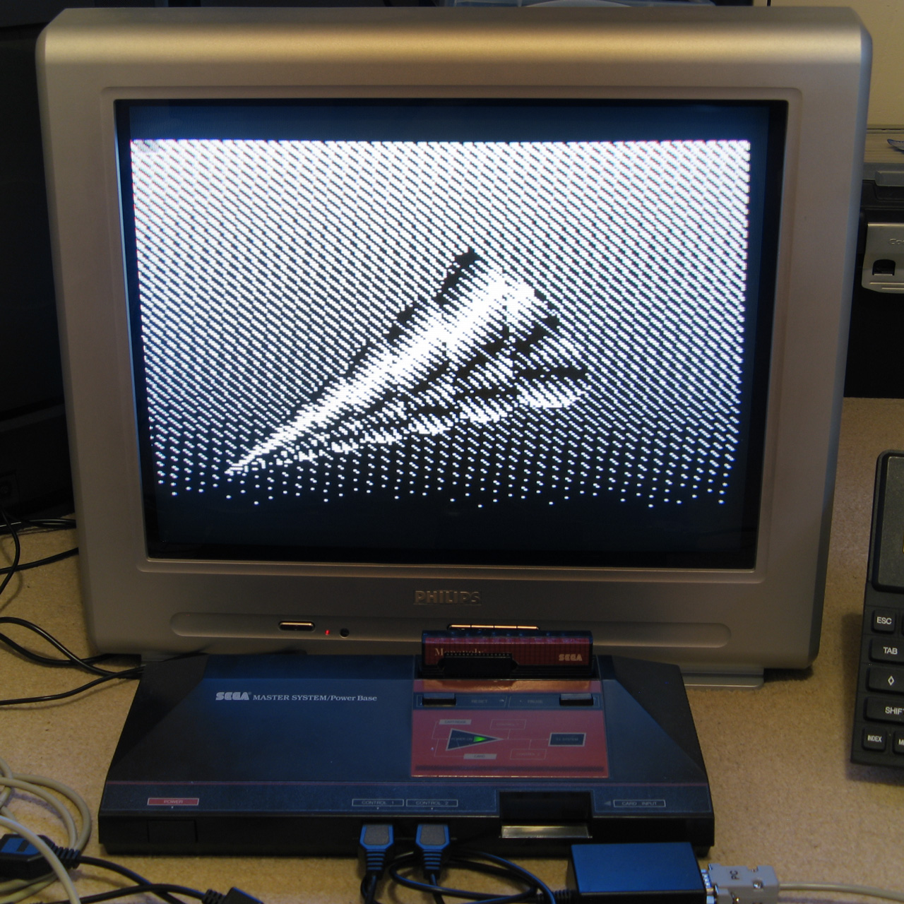
The video above shows a couple of programs being loaded from the BBC Micro Bot website onto the Master System. Even with the terrible audio to digital interface it gets the job done! The 7905=7905 messages at the end of each block during loading show the CRC-16 calculated for the received data followed by the expected CRC-16, as they match it indicates the data is getting through successfully.
Emulating the tape interface
As alluded to above my current loading system works well enough when everything is OK but it gets a bit confused when there's a fault. I never really planned out how to handle this and the code's a bit of a spaghetti mess in places so I drew out a flowchart of a more robust loader, which itself is also a bit of a mess but hopefully one that will make loading tapes more user-friendly and robust.
Unfortunately, doing any work on this interface has been very tedious as every time I make a change I need to try it on real hardware – I don't know of any Master System emulators that include tape support! I've been using my own Cogwheel emulator throughout which is itself not a very good emulator (there are no proper debugging tools, for example) but I can at least bolt on weird features I need like PS/2 keyboard emulation, so I thought it would be a good use of my time to add tape interface emulation. I started by writing a UEF (Unified Emulator Format) parser that could turn a UEF image file into a 4800 baud bitstream that could be fed into the Master System's controller port. For some reason my files end up being slightly different lengths to the sound files generated by PlayUEF – nothing major, but a handful of seconds over the length of a roughly 7 minute file. I tried loading the generated bitstream as a 4800Hz sample rate file into Audacity and it didn't quite line up with the audio file generated by PlayUEF either, but after poring over the specifications for the UEF format I was unable to figure out where the discrepancy lay.
Undeterred I pressed ahead and added this simple cassette player to the emulator, which happily seems to work well in spite of the reported timing differences:
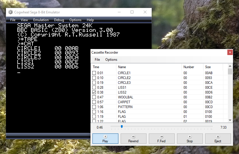
One thing that's notable there is that the program CIRCLE2 appears in the catalogue on-screen. When I first added the cassette interface emulation it was missing, but it would not be detected on real hardware either, which made me quite happy! Being able to more rapidly make and test changes to the tape loader code I was able to experiment and found that the tape loader seemed to miss the synchronisation byte ($2A) sent at the start of block headers on the CIRCLE2 program. This seemed to be due to going out of sync with the bit stream in the period between detecting the carrier tone and the first start bit, so I changed the code to demand exactly two 1200Hz half-waves as the start bit rather than using my more lax code that decodes the contents of the main bit stream that allows for extra 2400Hz pulses. This ensures that the start bit is always properly synchronised, and after making this change CIRCLE2 appeared in the catalogue as it should. I then reflashed the ROM chip on the cartridge and tried on real hardware, and that now picks up CIRCLE2. Being able to fix a problem that appears on hardware by replicating and resolving the same issue in software emulation justifies the few hours I spent adding the cassette tape emulation!
Unfortunately, I'm down to under a hundred bytes of free program space on the 32KB ROM I've been developing with, and I still have a lot of features I'd like to add (including the more resilient tape loader). I've been trying to put this moment off as long as possible as I'm going to have to use bank switching to map in additional memory banks, and that means a lot of difficult decisions about what code lives on which ROM pages to minimise the amount of switching that's required. Conventionally slot 2 is used as the slot to map different banks into but at the moment that's where I've mapped in the cartridge RAM to extend BASIC's memory. On the plus side very little of my code needs direct access to BASIC's memory (I mostly use my own data storage or the stack which lives at the top end of memory, far above slot 2) so this would seem like a good fit but I currently allocate storage space in BASIC's free memory for some operations (e.g. as temporary space when copying data around the screen during scrolling operations) so I'll need to change that code to use memory allocated elsewhere. It's not the most glamourous part of the project, but it'll need to be done if I am to add all the features I'd like.
Patterned fill modes for the Master System version of BBC BASIC
Tuesday, 10th August 2021
One of the features I was quite happy with in the TI-83 Plus version of BBC BASIC was the dithered fills used to provide some semblance of different colours. Sixteen different patterns were provided between black and white:

As well as baking in the sixteen different dithered patterns I added a command that let you use your own pattern tile in a very hacky method (you'd allocate the memory for the pattern via DIM and then pass the address of that memory to GCOLPAT – the extra "PAT" statement after GCOL is what did the trick).
What I didn't realise at the time is that the BBC Micro also had support for patterned fills via its Graphics Extension ROM and a much more natural way to interact with it – GCOL 16,0, GCOL 32,0, GCOL 48,0 and GCOL 64,0 let you select one of four pattern slots, and you can redefine the patterns with VDU 23,2,… to VDU 23,5,… followed by 8 bytes of pattern data, similar to how user-defined characters are already programmed.
Armed with the Graphics Extension ROM's user manual and sample programs I went ahead and implemented these patterned fills in my four- and sixteen-colour modes. Here's the output of the "shades" program, which runs in a four-colour mode and generates dithered fill patterns for the triangle to simulate different shades:


Depending on the number of colours of the screen mode you're currently in the 8×8 bitmap used as a fill pattern is interpreted differently; in the 16-colour mode it represents a 2×8 pattern that is repeated four times horizontally, in 4-colour mode it represents a 4×8 pattern that is repeated twice and in 2-colour modes it's a complete 8×8 pattern with no repetition. I like the idea of these 8×8 patterns so added a new two-colour video mode, mostly based on the existing four-colour mode but with the palette limited to two colours and the revised rules on interpreting fill patterns. This produces results like the following from the "pattern" demo program:


I've also implemented VDU 23,11,… (it resets the four patterns to their initial values) and VDU 23,12,… to VDU 23,15,… – these are helper commands that let you populate a fill pattern from a 2×4 list of colour values that is then repeated across the specified pattern number regardless of the current screen mode and without you needing to perform the bitwise arithmetic to pack the different colour values into memory properly. You may have also noticed that the four patterns are spaced sixteen GCOL numbers apart from each other (16, 32, 48, 64) – this is because you can use these pattern fills in conjuction with the logical plotting modes, e.g. GCOL 16+1,0 will OR the pattern over the existing screen contents.
These pattern fills apply to all graphics operations, so if I break out of the shaded triangle program above when it's settled on a particularly garish palette and switch to outputting text as graphics with VDU 5 I get results like the above. I'm not sure how practical or useful that would be but it does at least show how flexible the graphics plotting system is.
Better plotting modes, text anywhere on the screen and double-height characters for Sega Master System BBC BASIC
Monday, 9th August 2021
I've made quite a few changes to the way colours and plotting modes are handled in the Sega Master System version of BBC BASIC; previously this was handled on a per-graphics-mode driver basis, but this resulted in a lot of duplicated code and some inconsistencies. The new code is a bit more straightforward but also adds quite a few new features, most obviously different plotting modes:
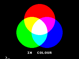
Plotting with the OR mode
The above screenshot shows the result of filling three circles with the OR plotting mode. The red circle is colour 9, the blue one is colour 10 and the green one is colour 12. Where the colours overlap they are ORed together when drawing, so for example red OR blue is 9 OR 10 which is 11, the colour code for magenta, hence the colour between the two is magenta. Where all three colours mix, that's 9 OR 10 OR 12 which is 15, the colour code for white.
It's the logical colours (the palette indices) that are combined by these plotting operations, rather than the RGB values, it just happens that the stock palette lines up neatly with the RGB values!
Another addition I've made is support for VDU 5. In normal operation, text sent to the display is displayed at the text cursor position. In VDU 5 mode the text is instead drawn at the graphics cursor position, which allows text to be drawn anywhere on the screen, outside the confines of its usual grid. It also takes into account the graphics plotting modes mentioned above and so you can blend text with other graphics operations. Here's an example:
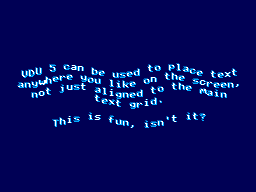
The somewhat blurry text has been drawn in two passes slightly offset from one another, once with colour 1 and again with colour 2, ORed together so that where the text overlaps you get colour 3, which is white. The program for this is as follows:
 10 REM Draw wavy text in a watery style.
 20 MODE 2
 30 REM Set up a suitably watery palette.
 40 COLOUR 0,0,0,64
 50 COLOUR 1,0,64,128
 60 COLOUR 2,0,128,255
 70 COLOUR 3,255,255,255
 80 REM Draw text at the graphics cursor position.
 90 VDU 5
100 REM How many lines of text will we draw?
110 RESTORE
120 L%=-1
130 REPEAT READ L$
140   L%=L%+1
150 UNTIL L$=""
160 REM Draw in two passes, slightly offset, in OR mode for a blurry effect
170 FOR C%=1 TO 2
180   GCOL 1,C%
190   RESTORE
200   Y%=(960+L%*50)/2
210   REPEAT READ L$
220     IF LEN(L$)>0 AND L$<>"-" PROCWAVES(L$, C%*4, Y%-C%*4)
230     Y%=Y%-50
240   UNTIL L$=""
250 NEXT C%
260 REM Restore normal text operation.
270 VDU 4
280 REM Wait for a key then exit.
290 REPEAT UNTIL INKEY(0)=TRUE
300 REPEAT UNTIL INKEY(0)<>TRUE
310 END
320 REM Draw some wavy text at X%,Y%
330 DEFPROCWAVES(TEXT$,X%,Y%)
340 LOCAL I%
350 X%=X%+(1280-(LEN(TEXT$))*35)/2
360 FOR I%=1 TO LEN(TEXT$)
370   MOVE X%,Y%+20*SIN(X%/80+Y%/160)
380   X%=X%+35
390   PRINT MID$(TEXT$,I%,1);
400 NEXT I%
410 ENDPROC
420 REM Text strings to display.
430 DATA "VDU 5 can be used to place text"
440 DATA "anywhere you like on the screen,"
450 DATA "not just aligned to the main"
460 DATA "text grid."
470 DATA "-"
480 DATA "This is fun, isn't it?"
490 DATA
When you're finished you can use VDU 4 to return to the normal text mode. In the video modes where I've had enough free VRAM to spare for it I've also added support for user-defined characters. You can send 23, then a character number, then eight bytes of pixel data for the 8×8 character bitmap to the VDU and then use that data for subsequent text operations (the characters from &80..&FF can be redefined). These user-defined characters can also be used as 8×8 sprites when combined with VDU 5.
I'm having quite a lot of fun writing my own test programs but it's also been useful to be able to run existing software as a test. I've tried to improve my sound handling and it now sounds a bit more faithful to the BBC Micro (though the Master System is a slower machine, so it can't quite keep up with more adventurous pieces of music).
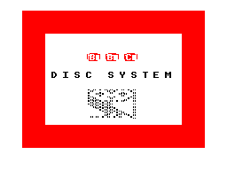
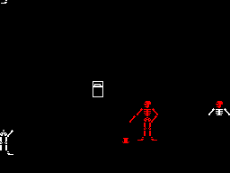
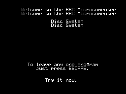
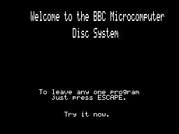
The BBC Disc System "Welcome" screen and the Bones demo
With the new graphics plotting modes and VDU 5 support the BBC Disc System "Welcome" program runs, for example, though it looks a bit rough around the edges due to mismatches in the video modes. Bones also runs, however the mismatch is even more severe here and half way through the skeleton turns red as it's running in the four-colour video mode and COLOUR 1 is mapped to red, not the white in the monochrome mode the demo is expecting. The misalignment comes from differences in the number of rows and columns of text that are available; the demo mixes graphics commands (which are mapped reasonably closely to the BBC Micro's screen) and text; if the demo expects the screen to be 40 columns wide and the best I can offer with this hardware is 32 columns, it won't line up! Of course, the BASIC program can be tweaked to get it working properly, but it's fun to see just how close it gets without any tweaking...
One recurring issue, however, is with programs that expect to be able to use Teletext features. The BBC Micro's default video mode used a Teletext character generator, which allows for bright colourful text and some limited graphics support in very little memory. I had previously mapped this mode to the TMS9918A text mode, which allows for 40 characters in 24 rows, just one row short of the BBC Micro's 40×25. It's a fast mode and is good for program editing due to the large number of text characters on screen at a time (all other modes are 32×24) however it is very limited - there's no support for colour, for example, other than the global foreground and background colours.
To provide some colour support I loaded the character set into memory twice, once normally and once inverted, so via the COLOUR statements it's possible to inject some variety into this mode. The BBC Micro's Teletext MODE 7 doesn't support the COLOUR statement, it relies on embedding special control codes in character positions on the screen that affects the rendering of the rest of the text in the line – for example, a command might change the colour, or cause the rest of the line to flash. As I can't possibly support such codes, I just ignore them, and the programs run fine but look a bit bland.
The main exception to this, I've found, is the double-height text mode. You can switch this on within a line by storing the value 141 in a character cell and then off again with 140 afterwards. This will only display the top halves of the characters, so to display the bottom halves you need to output the same content on the line below. A lot of BBC Micro programs seems to take advantage of this feature, so most programs I'd tried ended up having doubled-up text like you can see in the screenshot above.
The character set I'm using is only 96 characters long (32-127) but I had avoided investigating this as I assumed I'd need to triple the number of characters - the regular-height ones, plus the top and bottom halves of the doubled characters. 96×3=288 which is more than the 256 characters we have available, so I didn't think this would fit.
However, I did think that maybe some characters shared parts - for example, the top halves of the colon and semicolon are the same, and the bottom halves of the semicolon and comma are the same, so I wrote a quick program to count how many unique patterns would be needed and found that it would only take 225 patterns in total, well within our 256 pattern budget!
I set up a new video mode based on the original TMS9918 text mode. This generates these 129 additional patterns for the double-height characters when initialised, and also checks the nametable when outputting characters to see if there's a "double height" control character in the same line to determine whether it should pick one of the stretched characters (picking a top or bottom half depending on whether there are an even or odd number of lines above it that also contain the double height control character).
This new mode does lose the inverted text, but I think the double-height text will be more useful in practice – or at least is better at making programs look less broken!