Updated TI-83 Plus BootExec with USB "Silver Link" support
Sunday, 4th June 2023
This is a quick update to the TI-83 Plus BootExec program described in a previous journal entry. The program now supports the USB "Silver Link" cable (as well as the serial "Black Link" it previously supported) though to access the USB device you do need to temporarily replace TI's supplied driver with a generic WinUSB one which can be organised with Zadig.
The updated application can be downloaded from the same link as before: ti83p-bootexec.zip.
Unbricking a TI-83 Plus calculator with a link buffer overflow
Friday, 2nd June 2023
A few years ago I started running into problems with my TI-83 Plus graphical calculator. I was unable to install applications – it would keep locking up when "defragmenting". In the end I attempted to reinstall the operating system to see if that would cure matters, but that failed too and in the process left the calculator in a state where it wouldn't boot at all. Switching it on you'd be presented with a screen prompting you to reinstall the OS:
Waiting...

Please install
calculator
software now.
If you tried to install the OS over the link port it would switch to a progress screen but then get permanently stuck at the 0% mark until you pulled a battery out.
I eventually found a program called Overflow by Brandon Wilson which described similar symptoms and a possible cause – a corrupt certificate page. Considering the problems I'd been having with the flash ROM before attempting the OS reinstallation it seemed possible that my certificate page might have become corrupt and that was preventing me from reinstalling the OS.
The Overflow program describes a technique whereby it can transfer a user-supplied program to the target calculator by sending a very large variable packet and taking advantage of a lack of bounds checking in the calculator's boot code. Unfortunately, I was unable to get it to work on my TI-83 Plus, in spite of many repeated attempts. I eventually bought a replacement calculator, though being a newer model and built to a much cheaper standard I was always a bit disappointed that my original calculator was lingering, bricked, in a drawer.
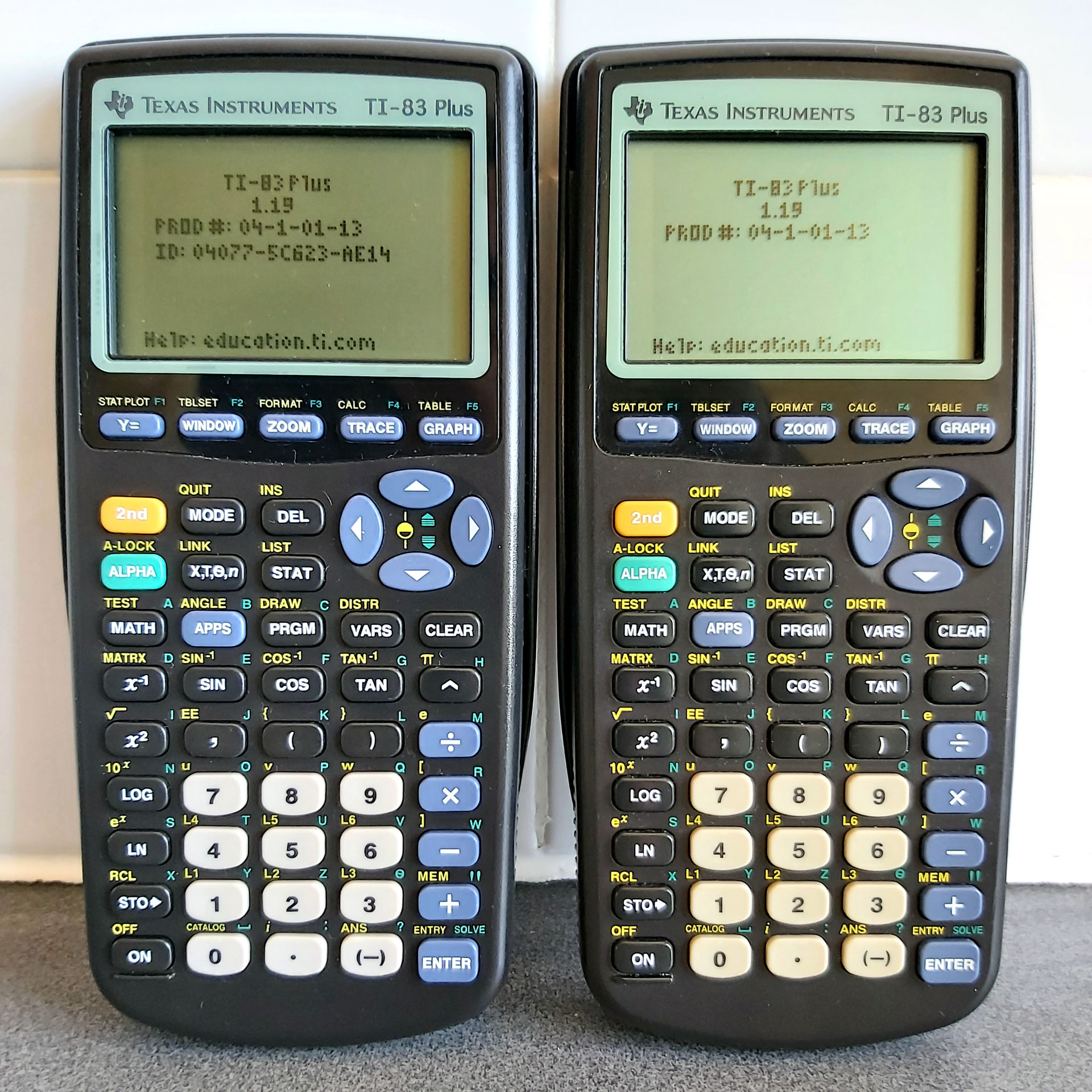
Photo of the repaired calculator (right) next to the its temporary replacement (left) – note the missing ID on the repaired calculator.
More recently I decided to revisit the problem, got a better understanding of just how the Overflow program worked and found a way to get it work on my original TI-83 Plus. The photo above shows the two working calculators I now have, though as I ended up having to erase the certificate page on the one on the right it now lacks an ID.
How Overflow works
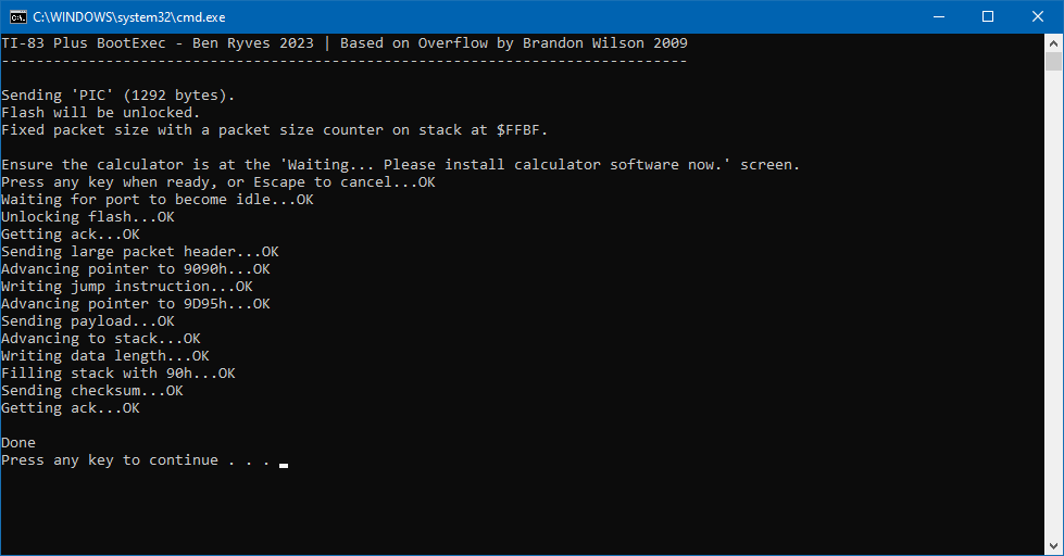
The basic technique exploited here is that the TI-83 Plus boot code does not bounds-check the length of the link packet we're sending it, so by sending a very large packet we can overflow the intended buffer right up to user memory, send over a program we wish to execute, and then overwrite the Z80 stack with the address of our program so that when the link routines return it executes our program rather than returning to the boot code.
Overflow satisfies this process by filling up the memory as described above, then sending some correcting data so that the checksum for the oversized packet is equal to zero, and then sending a constant stream of zeroes until the transfer fails. The last two bytes of a transfer are the checksum, and by previously correcting the packet's checksum to zero this means that the packet will be seen as valid.
At this point the transmitting calculator detects the link error and tries to read back the acknowledgement from the receiving calculator, and all should be well.
Unfortunately, the TI-83 Plus seems to be more fussy about how it handles linking errors and once the attempt to send too many zero bytes has failed it just displays an error message and switches off, rather than letting us receive the acknowledgement before executing our payload.
Looking at the documentation for Overflow it seems to have been intended more for the TI-84 Plus series calculators,
so it could be that they are more forgiving of the linking errors.
Trial-and-error with zero padding
If the problem is that we're sending too many zero bytes, one option is to count how many zero bytes we can send successfully. Once the attempt has failed, we can then make sure that on our next attempt we only send just the right number of zero bytes (based on our previous count) and no more, then check for the acknowledgement from the receiving calculator. To my delight this strategy works well, and is provided by the application's -zeropad option.
Unfortunately as over 30,000 zeroes need to be sent each time the exploit packet takes a long time to transmit and as we now need to do it twice this can really slow things down! Once a safe number is known this can be specified with -zeropad=<count> but it's still a time-consuming process.
Fixed-size packets for quicker transmission
The problem here is not knowing the size of the packet we're transmitting. The packet does start with a length parameter, however as the "number of bytes left to receive" counter is stored on the calculator's stack by the receiving routine we end up overwriting that with our exploit payload and the total number of bytes left to receive will end up depending on the particular stack level at the time.
In my testing the variable ends up being stored on the stack at the same address ($FFC1 for normal transfers, $FFBF for ones where the flash was previously unlocked). Knowing this means that as we trample over the stack deploying our exploit we can at least make sure that we leave that value in the state it should be for the current point in the packet transfer.
This is implemented in the program with the -fixed parameter, which executes much more quickly than the -zeropad one and only needs to run through once. It is however reliant on knowing exactly where on the stack the "number of bytes left to receive" variable is stored; if it's different from the two presets baked into the program it can be changed with -fixed=<hex addr>.
The program itself
In case it helps anyone else out, the program can be downloaded from this link. It's a .NET application and requires a computer with a serial port and a "black link" compatible serial cable (I use a home-made cable), which I appreciate is not exactly the most modern solution but is what I have access to.
It will allow you to transfer a standard "noshell" TI-83 Plus assembly program to the target calculator, with or without flash unlocked. As this is a potentially risky operation (especially with flash unlocked, which would allow you to completely brick the calculator by damaging the boot code) any such programs are left as an exercise to the user to be used at their own risk. The original Overflow program contains much more useful information, including a sample program that can erase the certificate page, though be warned that as written is is not designed for the TI-83 Plus and will erase the wrong page and so will need to be modified before use. This is only recommended as a last chance for calculators that are otherwise bricked and unusable!
Update 4th June 2023: The program now supports the USB "Silver Link" cable, though you will need to temporarily replace TI's driver with a generic WinUSB driver using Zadig. The download link is the same as before.
Update 7th June 2023: The program will now try to use TI's driver for the "Silver Link" USB cable, if available. This avoids the need to temporarily replace it with the WinUSB driver.
Using a VDrive to access USB flash drives from a Cambridge Z88
Saturday, 13th May 2023
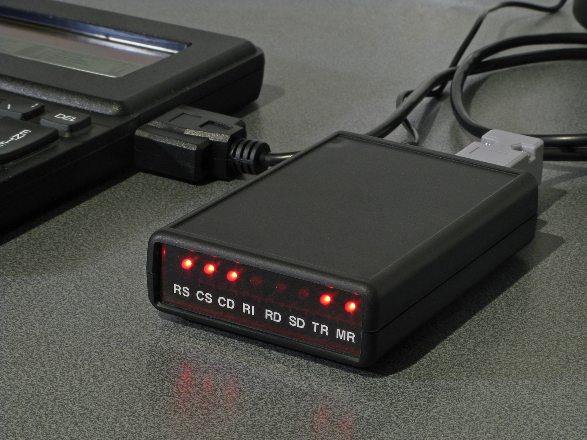
The VDrive is a handy module for electronic projects that need to access files on a USB flash drive. It's based around a USB host microcontroller and comes preinstalled with some firmware that provides control over the drive with simple commands sent via a serial connection (UART or SPI).
A few years ago I started putting together some code to connect the module to my Cambridge Z88 computer. All I needed was a way to power the drive and a MAX232 chip to translate the computer's RS-232 interface to the VDrive's logic levels, and after around 150 lines of BBC BASIC I had a program that could show directory listings, let me browse folders, and fetch files from the USB drive to the Z88's file system.
This worked well enough but was a bit clumsy. For example, to maintain good performance rather than alternate between reading a single byte from the drive and writing it to the local file system it's better to read and write larger chunks at a time. BBC BASIC doesn't provide a built-in way to do that, though you can read or write CR-terminated strings. When you read each part of the file this way you therefore need to decide whether the string you've just read is a certain length because you've reached a CR terminator (which isn't included in the read string), whether you've reached the end of the file, or whether the string buffer is full, and from that piece the file back together. I got this working quite well but it's still fundamentally an inelegant hack. Doing it properly would require some assembly code, and that would also be required for some other operations (such as properly transferring date and time modification information) that are otherwise not possible from pure BASIC.
Fortunately, BBC BASIC has a built-in assembler and that makes integration of assembly code in BASIC programs quite a bit easier than it would otherwise be. However, as I considered the amount of assembly code required would be quite high, I thought it might be more sensible to just rewrite the program as a native Z88 popdown application.

Status dialog shown when fetching a file from the drive
This is what I ended up doing, and it can be downloaded from its product page. It was quite a lot of fun to learn my way around the Z88's OS – not just for things like file handling, date and time manipulation, and integration with menu and help system but for some of the challenges involved in writing Z80 code for a system that shares memory between multiple running applications (and the file system) rather than my usual environment of having a big block of contiguous RAM to do whatever I fancied in.
The directory listing is the most obvious place where I had to rely on dynamic memory allocation. Each file or folder name being sent in a directory listing by the VDrive is allocated its own memory and I arranged the names together in a linked list that is sorted with an insertion sort.
Being my first Z88 application it's not especially well written but I've been using it for a while now and it seems to work well enough so I've released it, both on this very website and on GitHub.
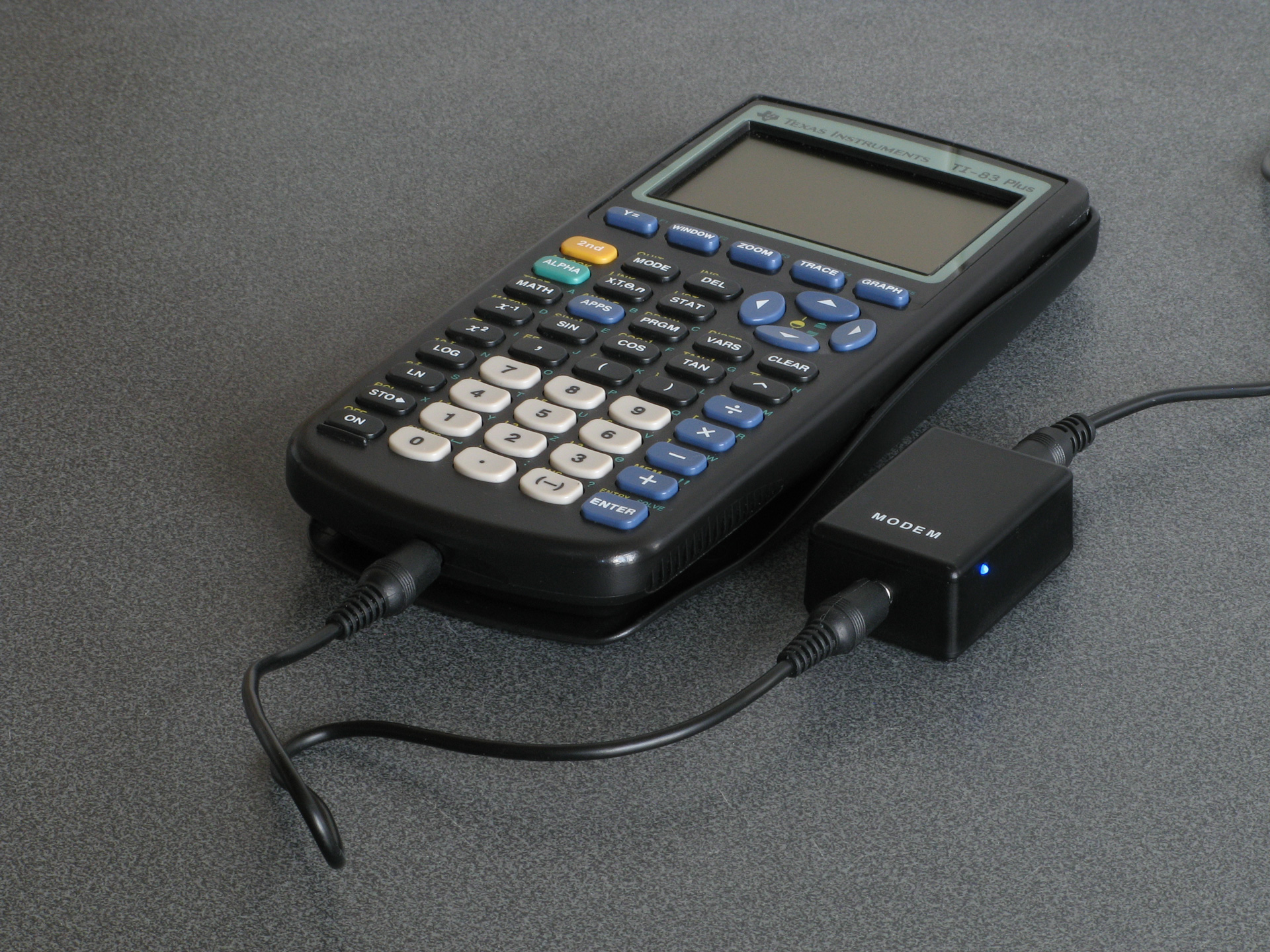
Take your TI-83 Plus online with a TIWiFiModem
Monday, 27th March 2023
One of the issues holding me back with my development of the Light Gun Commando project (aside from a lack of free time due to the day job) was running out of prototyping breadboards and the difficulty of swapping between different console adaptor boards for testing.
Normally by this point I'd have started soldering together more permanent prototypes on little circuit boards, but I've been having a difficult time with the boards I've got in stock apparently being made of a metal that's impossible to solder to. They were very cheap, but for some reason the solder joints would end up coming out blobby, make poor connections, be prone to bridges and generally not "wetting" the pads at all. This makes hardware prototyping very frustrating and time-consuming, and though I'd tried different solder (no change), different temperatures (higher heats just meant the pads would unglue from the board more quickly), more flux (just more cleaning required afterwards) and other attempts to clean the boards before use (including light sanding) I wasn't getting very far.
I eventually bought a set of new circuit boards from a more reputable seller but before cracking on with my light gun adaptors I thought I should try a more straightforward weekend project and I ended up building myself a RetroWiFiModem.
This is a device that looks like an old dial-up modem and though it does have an RS-232 serial port on the back to connect it to a computer it doesn't attach to a phone line but instead connects to a modern Wi-Fi network. You can send it Hayes-style AT commands and "dial out" to a domain name which will then open a Telnet (or raw socket) connection to the remote computer and allow you to exchange data. As long as your old computer has a terminal emulator on it you can use this to connect to and browse online services such as BBSes.
I had a lot of fun building this and setting this up – especially as I can confirm that the circuit went together extremely easily on my new prototyping circuit boards – and it reminded me that I'd seen a terminal emulator program for the TI-83 Plus calculator around 20 years ago by the name of Telnet 83 Plus. The documentation accompanying the program had lots of information in it about how to connect to a modem using the calculator's grey serial link cable which directly translates the calculator's link protocol to true 9600 baud RS-232, unlike the black cable which I owned which just uses the control lines to bit-bang the calculator's link protocol. As I never had the equipment for this the program only ever ended up being a curiosity to me, but having seen how well the RetroWiFiModem worked I thought it could be adapted for use on a calculator.
To do this I wrote a simple implementation of the calculator's link protocol in a class that inherited from the Arduino's Stream class. This is the same class that the Serial class inherits from, so having done that all I needed to do was a find-and-replace of Serial.* in the original source code with tilp.* and I had a version of the RetroWiFiModem that worked when connected to a calculator. As I also wanted this version to be a little more pocket-sized I designed it around the cheap ESP-01 or ESP-01S modules, which lacks the pins to drive the status LEDs on the original version so this ended up being a slightly more slimmed-down version of the project. It still has all the networking features, though, and the end result is the TIWiFiModem:
To interact with the modem I was using Telnet 83 Plus however I'd encountered a few bugs with this program, including incompatibility with newer TI-83 Plus calculators with slower display drivers (resulting in a scrambled image on the LCD), a lack of overflow checking on the receive buffer that would cause it to truncate long transfers and the inability to type certain keys in uppercase. Fortunately the source code was included so I dusted off my Z80 assembler and fixed these issues, along with shaving a few thousand bytes off the program size, improved compatibility with some VT100 sequences, a mode that automatically keeps the cursor within the view of the screen and local echo. These changes, along with the firmware for the modem, can be found on the TIWiFiModem Github page.
If you'd like to see what the TIWiFiModem is all about before building one yourself, I put together a video demonstrating it which is embedded above.
Adding Xbox controller support to Light Gun Commando
Tuesday, 24th January 2023
After building a USB Guncon 2 adaptor for my Light Gun Commando project the Xbox seemed like it should be the next console to support as that also uses USB for its controllers. The xboxdevwiki seemed like a good starting point for information about its controller protocol. I wanted to be able to compare against real Xbox controllers too, so I bought an Xbox controller cable online and cut it in half so I could use the plug end to connect my circuit to the Xbox and the socket end to connect Xbox controllers to my PC.
This extension cable proved to be the first hurdle, as connecting an Xbox controller to my PC did absolutely nothing! When I checked the connections I found out why – in spite of the Xbox controller using the USB protocol and official cables using the USB standard colours (plus a yellow wire for video sync), this extension cable used its own colour scheme where +5V was on the black wire and ground was on the red wire. I suppose the moral of the story is to double check with a multimeter before wiring anything up, but fortunately no harm was done!
After connecting the Xbox controllers to my PC I started writing a program to query them using the documentation on the xboxdevwiki. I have put together an application similar to USBView that can display information about a connected Xbox controller, as well as preview the live state of a controller and send output reports to it. The source code for this is available as XboxControllerAnalyser on my Github account, the code is rough and ready as it was really just intended to be my development testbed but I thought it worth sharing in case someone else found it useful.
With a decent grasp of the Xbox's controller protocol, I started implementing a simple controller using the V-USB library on an ATmega328p. This had worked for the Guncon 2, and I was able to build something that worked in my Xbox Controller Analyser application, matching the reports from a real controller.
Unfortunately, I was unable to get the controller working on a real Xbox. Logging the activity it looked like the Xbox would start issuing a few requests, but then give up after a few attempts. The reports I was sending back matched what I could see from a real controller, so I wasn't really sure what the issue was. Real Xbox controllers contain a USB hub, with the being a USB device connected to the internal hub (the other ports on the hub are exposed via the accessory slots on the controller) but my device was a plain USB device directly connected to the console. Maybe that was it?
I think a more likely explanation is that the V-USB firmware is only capable of implementing low-speed USB devices. These limit their endpoint size to 8 bytes (and a maximum poll rate of once every 10ms) whereas the Xbox's input reports are 20 bytes long and the controllers report a poll interval of 4ms. I had set the interrupt endpoint to return the 20 byte reports in 8 byte chunks, and could read these back successfully with a single "read 20 bytes from this endpoint" request on my PC, but maybe the Xbox wasn't so happy about this.
Rather than rely on V-USB's software bit-banged USB I decided to switch to an ATmega32U4 instead, in the form of a cheap Arduino ProMicro board. This is a similar 8-bit AVR chip to what I'd been using already, but has hardware USB support and a good library called LUFA to assist with the USB hardware.
Sure enough, after adapting my code from V-USB to LUFA I was able to get the Xbox responding to a Master System control pad!
Was struggling to get V-USB to mimic an Xbox controller, but yesterday had a go with LUFA on an ATmega32U4 with its dedicated USB hardware and was very happy to finally get it working. Dead or Alive 2 isn't really made to be played on a Master System pad, though! pic.twitter.com/l8G5UHPCI3
— Ben Ryves (@benryves) January 12, 2023
Of course, the real goal here is to implement an Xbox light gun. The xboxdevwiki doesn't provide much particular information about how the Xbox's light guns work, so I needed to connect an original Xbox one to my PC to get a better idea of what was going on. The first thing I noticed is that the guns would not enumerate properly if they were not fed with a video sync signal. This is normally supplied by the Xbox console via the fourth pin in its controller ports (with a yellow wire) and used by the light guns to determine the timing of the video signal and therefore where the gun was aimed. I ended up connecting the Xbox guns to both my PC (VCC, D+, D-, GND) and Xbox (video sync, ground) with the Xbox displaying a bright image on a CRT so I had a good reference for something the gun could "see".
After doing this I found the Xbox light guns would enumerate fully and would send data back to the PC in much the same way that a regular Xbox controller would. There are only really two major differences:
- The controller subtype byte (sent in response to GET_DESCRIPTOR) is set to 0x50 instead of 0x01 for a "Duke", 0x02 for a Controller-S, 0x20 for an arcade stick etc.
- There are three additional bits set in the byte at offset 3 in the input reports (sent in response to GET_CAPABILITIES or GET_REPORT):
enum {
    XID_LIGHT_GUN_LIGHT_VISIBLE = 0x20,
    XID_LIGHT_GUN_UNKNOWN_1 = 0x40,
    XID_LIGHT_GUN_UNKNOWN_2 = 0x80,
} XID_Controller_Input_LightGunFlags_t;
The three additional bits result in a value of 0xE0 in the byte at offset 3 (between the bitmask for digital buttons at offset 2 and the analogue "A" button at offset 4) as reported by GET_CAPABILITIES. I don't know what two of these are for (they were always cleared in the reponse to GET_REPORT), but one (0x20) is the bit that determines whether the light gun can see any light in a frame (set if the gun can see light, cleared if it can't).
Light guns will report their position via the left analogue stick, with (0, 0) being the centre of the screen, (-32768, -32768) being the bottom-left corner and (+32767, +32767) being the top-right corner. If the light gun can't see the screen then it will also report a position of (0, 0) but with bit 5 of the third byte of the report cleared.
Another difference with light guns is that they'll generally report fewer axes and buttons than a regular controller, and will also only report a single force feedback motor. Oddly enough two of my light guns report that they only have a left force feedback motor, but only respond to requests made to the right motor. In practice this still works in games as they set both motors at the same time anyway, but it did strike me as a bit odd!
The House of the Dead III did get a Wii release so playing the Xbox version with a Wii remote isn't a massive achievement, but I'm surprised Silent Scope didn't end up on the Wii as it seems a natural fit for the controller. pic.twitter.com/i0kJtCBORL
— Ben Ryves (@benryves) January 13, 2023
With all this in place I was able to play some House of the Dead III and Silent Scope with my Wii remote, so I was very happy to get it working at long last. There was only one minor complication, which was that I couldn't get past the calibration screen in The House of the Dead without unplugging my circuit, bypassing the calibration with a regular controller, then plugging my circuit back in (Silent Scope had no such issue). After some further debugging it turns out the Xbox was sending a second type of output report to the controller that I wasn't handling, and though Silent Scope didn't care The House of the Dead III wasn't taking kindly to being ignored.
This light gun calibration output report is sent in the same fashion as the force feedback output report (via SET_REPORT) but with a wValue of 0x0201 instead of 0x0200. It's ten bytes in length and takes the following format:
typedef struct
{
    uint8_t bReportId; /**< Report ID. */
    uint8_t bLength;   /**< Size of the report, in bytes. */
    int16_t wInnerX;   /**< X offset to centre calibration target (0, 0). */
    int16_t wInnerY;   /**< Y offset to centre calibration target (0, 0). */
    int16_t wOuterX;   /**< X offset to top-left calibration target (-25000, 25000). */
    int16_t wOuterY;   /**< Y offset to top-left calibration target (-25000, 25000). */
} ATTR_PACKED XID_LightGun_Calibration_Output_Report_t;
Light guns are always calibrated in a two step process, and it's the light gun itself that handles the calibration, not the game software (the light gun should adjust its output to compensate for the calibration values it was previously sent). The first step's centre target is expected to be at (0, 0) and the second step's top-left target is expected to be at (-25000, +25000).
- The game will first send a calibration report with all four offsets reset to (0, 0), (0, 0) to reset any offsets and scaling.
- The game will now display a target in the centre of the screen and ask you to shoot it. This will tell it how "wrong" the gun is when aimed at where it thinks (0, 0) should be on the screen. If the gun normally shoots slightly too high and further to the right, it might report (1000, 3000) for example.
- The game sends a calibration report to the gun to negate the offset, e.g. (-1000, -3000), (0, 0) using our example of (1000, 3000) from before.
- The game will now display a target in at (-25000, 25000) on the screen and ask you to shoot it. This will tell it how "wrong" the gun is when aimed at the top left of the screen.
- The coordinates received from the gun will be subtracted from the expected (-25000, 25000) and sent back to the gun in the second part of the calibration report along with the values previously determined for the centre position. If the first calibration was enough to adjust the screen offset we might have seen the "perfect" coordinates of (-25000, 25000) in which case the report would be (-1000, -3000), (0, 0) again. However, if our gun read the coordinates slightly closer the the middle of the screen at (-20000, 22000) then the report would be (-1000, -3000), (5000, -3000).
All this is fairly academic, as in my case the Wii remote is already calibrated itself and sending "perfect" coordinates back to the Xbox, so I just ignore the calibration values – but by receiving the report rather than just ignoring it The House of the Dead III no longer gets stuck on the calibration screen.
The third and final light gun title for the Xbox is Starsky & Hutch, which is a two-player game where one person drives and the other shoots. It's just about manageable by one player if you have a steering wheel, but I don't have an Xbox wheel. I do have a rather good PlayStation 2 one, however, so after building an Xbox light gun I quickly cobbled together a PlayStation to Xbox controller adaptor and was soon able to drive and shoot my way terribly through Bay City:
Starsky & Hutch provides the opportunity for me to suck at two different game genres simultaneously. Wii remote would be more accurate if I was further from the screen (so it could see more IR LEDs) but I have no excuses for the shambolic driving! pic.twitter.com/yugUrWdHtl
— Ben Ryves (@benryves) January 21, 2023
This adaptor supports the DualShock 2 (including analogue face buttons), DualShock, Dual Analog, neGcon and Jogcon. It's not quite ready for general use (button remapping is currently handled by recompiling the code for specific games, not ideal!) but when I've got it tidied up a bit I'll share it as I was unable to find any other working projects that implement Xbox controllers on cheap microcontrollers.