A clock and a serial port for the Z80 computer
Tuesday, 17th August 2010
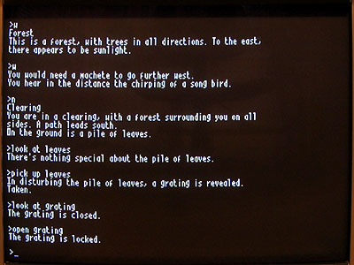
At the end of the previous entry I mentioned that I was going to start developing my own programs for the Z80 computer. The first is a graphical clock, taking advantage of my implementation of the BBC Micro's VDU commands and the ability to use those commands to draw graphics onto the screen as well as text:
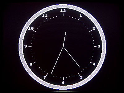
I have uploaded the code and binary to my site for anyone who is interested, though it will only work on a machine running CP/M 3 and that is equipped with a display that implements a handful of BBC Micro VDU commands.
The computer features a display for output and a keyboard for input which is sufficient if you're interacting with a human but it's often nice for computers to be able to speak to eachother, so I've added an RS-232 serial port.
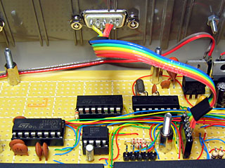
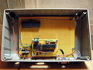
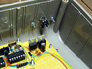
RS-232 is a bit of an unfriendly beast. Whereas the computer's logic uses 0V to indicate a logic low (0, "false") and 5V to indicate a logic high (1, "true") RS-232 uses around +12V for a logic low and -12V for a logic high. This requires that the outgoing signals are inverted and boosted and the incoming signals are inverted and reduced to protect the inputs of the receiver circuit. Fortunately you can easily get hold of chips that perform this task for you when aided by a number of capacitors; in my case I'm using an ST232, which is shown in the bottom left of the above photo. A DE-9M connector is provided on the outside of the case, much like the one you'd find on your desktop if you were trapped in the 1990s.
One issue I have yet to solve is handshaking. The serial port sends or receives data on two wires (TXD and RXD respectively). The receiver has to handle each incoming byte from the transmitter. As the receiver may be busy performing other tasks at the time it may end up receiving data faster than it can process it and it will start losing bytes. There are a number of different ways to avoid this problem. The simplest electronically is to use XON/XOFF handshaking; in this configuration, the receiver can send the XOFF byte to the transmitter when it's busy and the transmitter will stop sending data temporarily. The receiver can then send XON back to the transmitter when it's ready to receive more data. This technique has one major drawback it prevents you from sending binary data containing the XOFF or XON bytes.
An alternative solution is to add two wires to the serial connection Request To Send (RTS) and Clear To Send (CTS). These can be used to signal when each device is available to accept data. This allows you to send XOFF and XON directly over the serial port (extremely useful for binary data) yet requires the addition of two more wires to the port.
Unfortunately whilst implementing both techniques is possible, CP/M only internally refers to XON/XOFF handshaking; there is no way to select RTS/CTS handshaking. I think what I will end up doing is have CP/M's XON/XOFF refer to handshaking in general and then add a hardware-specific utility that lets me choose which particular type of handshaking I wish to use. This utility could also help me select other serial port configuration settings that CP/M doesn't expose (such as parity, number of stop bits or number of data bits).
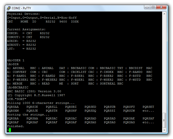
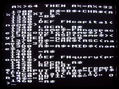
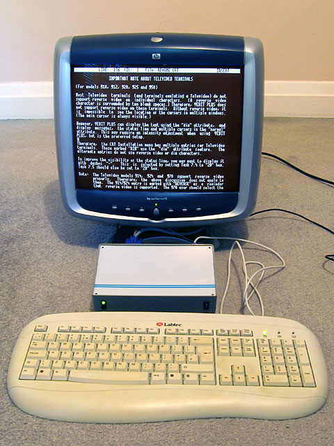
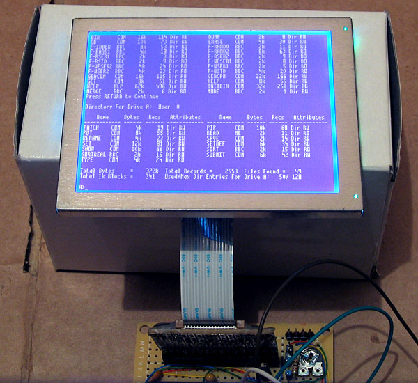
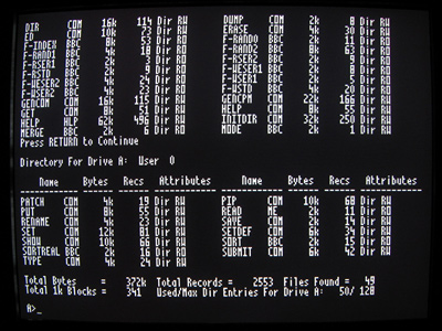
With the hardware installed, the AVR I/O controller updated to use it and the BIOS reprogrammed to expose it to CP/M it is possible to interact with other computers over the serial port. CP/M features five logical I/O devices: CONIN and CONOUT for general console input and output, AUXIN and AUXOUT for general "auxiliary" output and LST for printer output. The BIOS exposes two physical devices; CRT for the keyboard and video display controller and RS232 for the serial port. By using the DEVICE utility you can connect these logical and physical devices together. In the above screenshot I have connected the serial port to both CONIN and CONOUT. This allows me to connect my desktop PC to the Z80 computer using a null modem cable and use terminal emulation software (such as PuTTY) to talk to it.
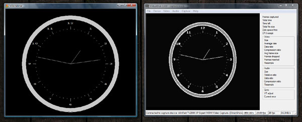
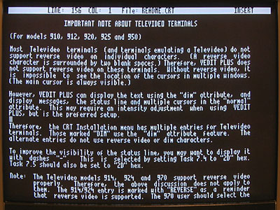
The above screenshot shows VirtualDub capturing the output of the video display controller next to an instance of BBC BASIC for Windows which is running the following program:
aux%=OPENIN("COM2: baud=9600 parity=N data=8 stop=1")
REPEAT
  REPEAT:UNTIL EXT#aux%
  VDU BGET#aux%
UNTIL.
This passes any data received over the serial port to the simulated VDU in BBC BASIC for Windows. As both video devices accept the same commands the result is that both show approximately the same thing.
I have been slightly improving the video display controller as I've gone along. One feature I had to add for the clock was the ability to draw text characters at the graphics cursor position, as opposed to the fixed text grid (this is used to draw the numbers around the dial). At the same time I added the ability to redefine the appearance of characters. One obvious use of this feature is to change the font, but when combined with the ability to render text anywhere on the screen some simple sprite-based games could be written for the computer. Each letter is just a 8×8 pixel sprite, after all.
Another feature I added was a simple implementation of MODE 2 where characters are stretched to sixteen pixels wide. You can't get much text on the screen in this mode but it may be useful for games.
A useful Z80 computer in a project box
Saturday, 14th August 2010
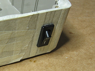
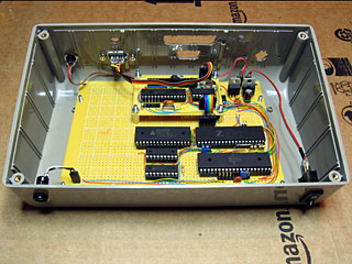
Work continues on the Z80 computer. The two final modifications to the box itself are the holes for the status LEDs and the power switch.
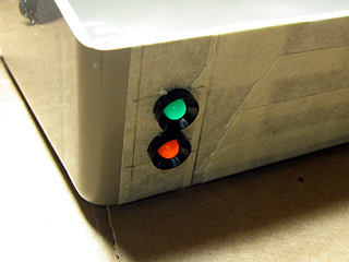
The green LED indicates power and the orange one disk activity. Unfortunately, the project box is fairly scratched on the outside (one scratch on the front is my own fault, but the sides and back were fairly scuffed and scratched when I bought it). If anyone has any tips for polishing scratches out of ABS I'd be glad to hear them; the usual household polishing abrasives (such as toothpaste) remove most of the light scuffs and result in a lovely mirror finish, but don't do anything to the deeper scratches. I'll probably invest in the finest grade wet-and-dry sandpaper I can find and have a go with that followed with a Brasso polish, and if that doesn't help (or makes it worse) just sand the whole thing down and paint it.
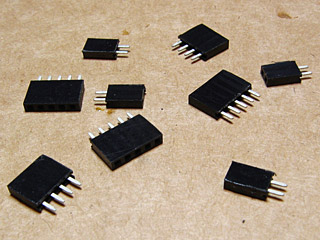
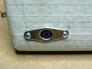
The circuit board inside the case needs to be attached to the case-mounted components somehow. In simpler projects I've resorted to soldering these connectors directly to the board, but this can make maintenance a problem (to remove the circuit board one would have to cut and resolder the wires). For this project I've left pin header strips on the board. The external connectors have leads soldered to them terminated with pin headers cut to size using some wire cutters and a rotary tool to polish them off; these headers are pictured above.
The main circuit board can then be easily installed or removed from the case as required. The small circuit board for the video display controller is connected to the main circuit board in the same way.
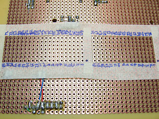
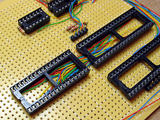
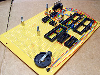
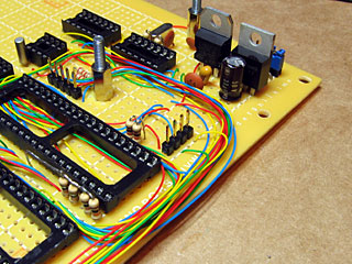
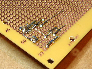
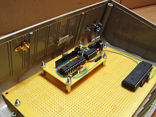
A Z80 computer can't live up to its name without some sort of a Z80 inside it, so I thought that that was the most obvious part to add next. Computers also generally need access to memory so I decided to add the 128KB SRAM chip at the same time. The Z80 communicates with the memory over an eight-bit data bus, a sixteen-bit address bus (to indicate which address in memory it is reading from or writing to) and a number of control lines (to indicate whether the current operation is a memory read or a memory write, for example). This provides a fairly tedious amount of soldering work; each pin on the memory needs to be connected to the corresponding pin on the Z80. To aid in the construction I stuck masking tape to the bottom of the perfboard around the outline of where the two chips would go and wrote the pin numbers onto the tape, shown in the photograph above.
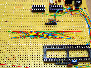
I put the two chips close together so I could put all of the bus wires on the inside of the IC holders rather than going around the outside. This saves a bit of space and avoids having to route the wires around the chip holders which gets a little untidy. The above photograph shows all of the wires in place before the chip holders were soldered in. Adding those in should be a quick and easy job, at least...
Well, you'd have thought so, but somehow I managed to solder in the 32-pin SRAM socket the wrong way around. Each socket has a notch to help you align the chip using its corresponding notch. As you can see in the above photo the notch points right when it should point left like all of the other sockets. It wouldn't affect the operation of the circuit (as long as the SRAM chip was inserted with the notch to the left) but it looks untidy and I may as well do the job properly.
On the positive side I suppose I got to practice my desoldering skills.
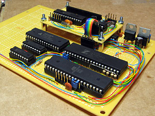
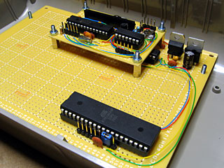
The computer design uses an AVR microcontroller to manage the I/O devices (such as the keyboard, video display controller and SD card) and to load the OS into the Z80's memory on reset. To achieve this the Z80 and the AVR need to be connected together. The above photograph shows some new wires between the AVR (bottom left) and Z80 (bottom middle) to connect the Z80's data bus to the AVR's PORTA and a number of other wires to connect the Z80's control lines to several other I/O pins on the AVR. A number of pull-up resistors have been added to control lines on the Z80 so that when nothing is driving the control bus they rise high (the de-asserted state). If left disconnected ("floating") the other components connected to the control bus may think these lines had gone low (asserted) and treat that as a read or write operation, corrupting data.
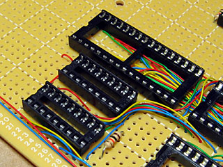
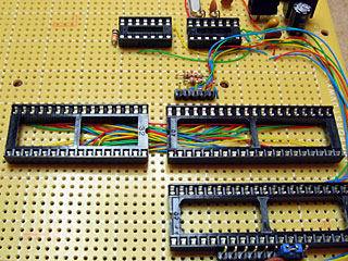
The AVR also needs to be connected to the Z80's address bus. This would take another sixteen pins if driven directly by the AVR; sixteen pins that aren't available to me! I am therefore using two MCP23S08 eight-bit I/O expanders, pictured above, to drive the address bus from the AVR. These are controlled over the SPI bus, which only takes up three pins on the AVR (these pins are shared with other SPI peripherals, such as the SD card) plus a single chip select pin that is unique to the I/O expanders. Four pins is better than sixteen, at any rate.
I keep mentioning chips even though the sockets are quite clearly empty in the above photographs. As I was approaching a useful computer circuit at this point I plugged all of the chips into their sockets to test the connections. As there was no SD card, real-time clock or keyboard I had to modify the boot loader on the AVR quite considerably; I started with a test program that wrote random data to blocks of memory then read them back to verify that they had written correctly. Once I had verified that the AVR was able to access memory correctly I reprogrammed it to copy a small Z80 program to memory and then let the Z80 take over. This Z80 program repeatedly output the string 'Z80' to the console output port. With everything plugged in I switched on the computer and saw the screen fill with Z80Z80Z80… so I was pretty certain that I'd wired everything up correctly!
At this point I could start reintroducing the various peripherals to the computer. A DS1307 is used as a real-time clock. This clock needs to keep running when the computer is switched off, so I've added a 3V battery connector to the computer to keep it ticking.
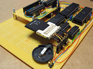
As the computer uses a 512MB SD card for storage, I have added a pin socket strip to the board to plug in the SD card slot I scavenged from a card reader. The card is connected to the SPI bus along with the I/O expanders used to drive the Z80 address bus. SD cards run at 3.3V rather than the 5V that nearly everything else on the board uses so I've used a series of voltage dividers to drop the voltage on each input pin from 5V to around 3V (the resistor values I have don't allow me to get to 3.3V; 3V is the closest I can manage without going over 3.3V). The video display controller board also runs on 3.3V so I do at least have a suitable voltage supply for the card!
The final part of the computer that was on the breadboard prototype but not yet in the final build was the keyboard connector. This is simply a four pin header on the board that is connected to the PS/2 port screwed to the case. However, when I tried to use the computer, the keyboard didn't appear to work. Pressing Num Lock, Caps Lock or Scroll Lock would toggle the associated LED and hitting Ctrl+Alt+Del would reboot the computer but no other key worked. This implied that the AVR was handling the keyboard correctly but the Z80 wasn't receiving any notification of key presses. A bit of digging identified the problem; I'd forgotten to connect the Z80's interrupt pin to the AVR! When a key is pressed the AVR triggers an interrupt to let the Z80 know that a key is available. By soldering a wire between the two chips it started working as intended.
The computer is now up to the same standard as it was when assembled on the breadboard, but is much more practical to work on. I hope to add a serial and parallel port to the computer soon, and would like to mount an LCD into the lid of the project box, but for the time being I am happy that I have managed to get this far.
One of the advantages of running CP/M on the computer rather than my own operating system is the availability of existing software. The above photograph shows the computer running VEDIT, which is an excellent visual text editor.
With the hardware in a decent configuration I can start writing my own software. I think the first CP/M program I'll write is a graphical analogue clock, as this is the sort of program that can be left running for long periods as a way to check the stability of the computer.
Mounting circuit boards and rear panel connectors
Monday, 9th August 2010
One of the fun things about working with electronics is that you can end up with a physical product at the end of your hard work. To this end I have started moving my Z80 computer from its current breadboard to a more permanent enclosure.
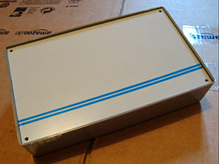
Large project boxes can be quite expensive (around £40, it seems), but the one I picked out was a slightly more reasonable £7. It's not the prettiest enclosure I've seen but it should be large enough to house the computer and provide space on the lid for the LCD and on the rear surface for a collection of connectors (as you'd expect to find on the rear of any computer).
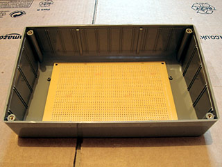
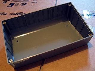
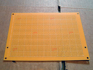
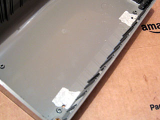
The first challenge was how I intended to mount the circuit board within the box. The perfboard I will use for the main computer circuit doesn't fit the marked mounting posts on the bottom of the project box; it's too narrow and too deep. What the photo doesn't show very well is that the perfboard is not able to lie flat in the box due to the curve at the rear of the box. To raise the board above the bottom of the box I decided to use four PCB spacers, which required two new holes to be drilled into the perfboard away from its corners.
I decided that the video display controller, which resides on its own board, should be mounted on the main circuit board using PCB spacers too.
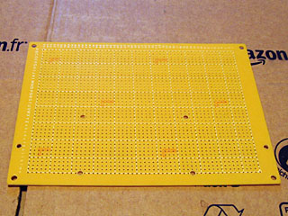
This required four more holes to be drilled into the main circuit board. I tried to align the small video display board so that its 16-way pin socket for connection to the LCD was as close to the horizontal centre as possible.
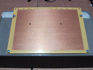
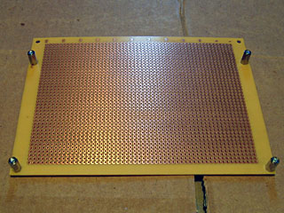
The base of the project box needed to have four holes drilled into it to support the main circuit board. Once the two nearest the front edge had been drilled, I screwed the circuit board to the back of the project box to mark the position for the other two holes to ensure that they lined up exactly with the holes drilled in the circuit board.
Screws come through the bottom of the project box to hold the main circuit board in place. Some sticky foam feet are provided with the project box which will raise it off the surface it is resting on to prevent these four screws from leaving scratches! Due to the curve at the back of the box the circuit board is only a few millimetres above its surface, which is why I reversed the screws holding the video display board to leave the long threaded ends pointing upwards.
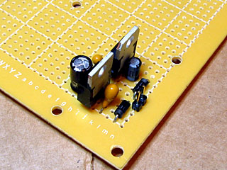
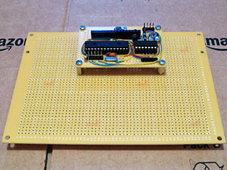
As working on the enclosure is a fairly noisy activity I switched my attention to the electronics for a brief spell. The first part of the circuit I assembled was the power supply; this just uses a pair of voltage regulators to provide 5V and 3.3V from an external power supply (I use a cheap wall wart affair rated at 7.5V DC).
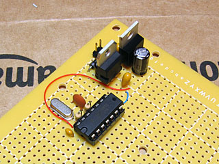
I decided that the next part to tackle would be the oscillator. This uses a 20MHz crystal and a 74LS04 according to the design on z80.info to generate a 20MHz clock signal which will be further divided by two to produce a 10MHz clock signal for the Z80. I had some real problems with this design; it would run at 20MHz until I attached a load to it, at which point it would generate a fairly random-looking signal or stop oscillating entirely. I experimented with a few different capacitors and found that if I remove the 120pF capacitor and replace it with a 33pF capacitor on the other end of the crystal it works reliably. I'm not entirely sure why this is, but it's the design I've been using for a while with the computer on a breadboard so I'm happy to keep it this way for the time being.
I added a D flip-flop to divide the 20MHz clock to 10MHz and then added the ATmega644P microcontroller to the board. This has a jumper next to its clock input allowing for the selection of either 20MHz or 10MHz operation; a pin header to the left of this jumper allows for it to be programmed in-circuit.
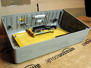
With those new parts in place I reinstated the video display board to check that everything still fit. My main concern now was how far the connectors screwed into the rear of the case would intrude and whether there'd be any problems with them getting in the way of the circuit boards.
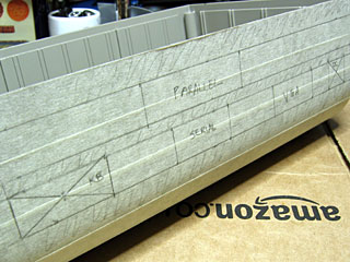
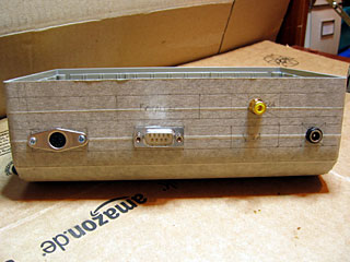
I sketched a design of how I saw the connectors would fit on the back of the case and then copied the layout to some masking tape stuck to the case. The computer naturally needs a power supply and keyboard input, and the video display board accounts for the VGA connector and an RCA connector for composite video (which I neglected to mark). I also hope to include a serial port and a parallel port in the final design (though neither are currently supported by the software) so left space for those two connectors.
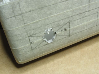
The 6-way mini-DIN connector for the keyboard is the deepest one to contend with so I decided to start with it. I cut the hole in the case by drilling a small hole in the plastic which I then enlarged with a burr tool to the correct shape and size.
Fortunately it looks like there's plenty of room in the case for connectors!
The next few connectors confirm this. I really do not enjoy cutting the holes for D-sub connectors (such as the one for the serial port); they don't have much of a metal lip to hide a botched hole, so I have to cut very slowly and very carefully, taking a very long time to slowly enlarge each hole until the connector fits. I'm therefore not really sure why I decided to have three D-sub connectors in this computer design; maybe I'm just a glutton for punishment.
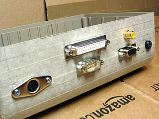
Finally, the rear of the case is completed. I will leave the masking tape on there as scratch protection until I have finished the front of the case (this will be significantly simpler — just a power switch, power LED and disk activity LED). Once that is done I can resume working on the electronics!
Integrating the dsPIC33 VDC with the Z80 computer
Saturday, 31st July 2010
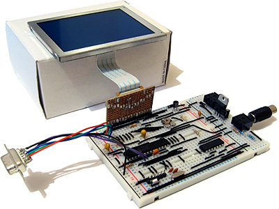
The ultimate goal for the video display controller module I have been working on is to drive the display in my Z80 computer project. As I have now got a pretty good set of features I thought it would be a good idea to join the two projects together.
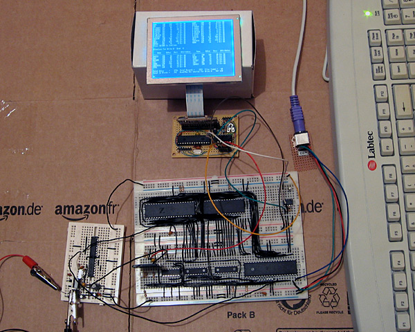
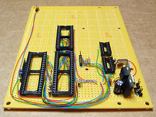
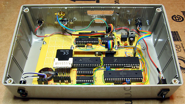
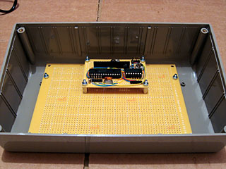
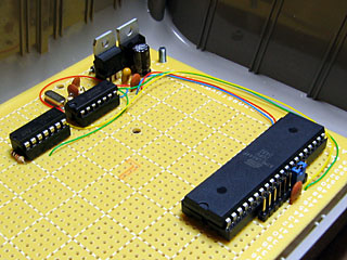
The big board in the lower middle of the above photograph is the main body of the computer, including the Z80, its RAM, the ATmega644P that is used to handle I/O, an SD card for storage and a DS1307 real-time clock. The small board in the bottom left of the photo is the power supply (supplying both 5V and 3.3V) and clock generator (providing a 20MHz and 10MHz clock).
At the top of the photo is the video display controller, connected to a 320×240 graphical LCD. A pin header is used to connect this VDC board to the rest of the computer. Three pins are required for power; 0V, 3.3V (dsPIC33 and output buffer) and 5V (LCD). The VDC is connected to the computer's ATmega644P I/O controller using the two-wire I2C bus (the same bus that is used to access the DS1307 clock). Rather than run a series of graphical demos, the VDC now waits for commands to be written to the I2C slave address 0xEE which it acts on to control what is shown on the screen. I'm aiming for these commands to work in the roughly same way as they did on the BBC Micro VDU, which should make porting the enhanced TI-83+ version of BBC BASIC to this computer a bit easier. The BBC Micro's VDU could be accessed by calling OSWRCH (assuming it was being used as the current output stream), which typically has an address of &FFEE — hence my choice of 0xEE as the I2C slave address!
A handful of these VDU commands have been implemented, which is sufficient to run simple CP/M software. The generic CP/M version of BBC BASIC does not, naturally, support any hardware-specific features and as such lacks advanced text or drawing support (one can send commands directly to the output stream with the VDU statement but this isn't very user-friendly). I will need to work on this now that the hardware is coming together! The current VDC code can be downloaded here if you are interested in the changes that have been made.
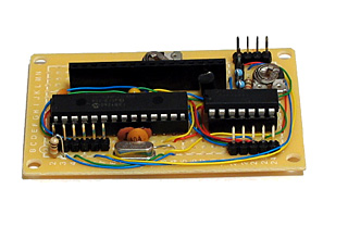
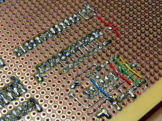
The above photo shows the newly constructed VDC hardware. All of my previous projects have been assembled on stripboard; as the projects have become more complex or simply smaller I've found stripboard to be increasingly awkward to work with. ICs can only really be orientated in one direction, and to reduce the size of circuits I've had to start cutting the tracks between holes (rather than the usual method which is to drill out an entire hole). The supplier I normally acquire parts from, Bitsbox, recently added three different sizes of perfboard to their catalogue so I thought I'd give it a go. I've found it much more pleasant to work with than stripboard, though not as easy to correct if you make a mistake and need to desolder a connection. You can certainly perform some interesting space-saving tricks on the underside of the board!
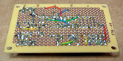
The Kynar insulation on the wire I switched to using also has the advantage of not melting when heated with a soldering iron, as I've had problems in previous projects where tightly-spaced wires will end up getting shorted together as the insulation between them melts.
I have mentioned that one pin header is used to connect the VDC to the computer. There are three others on the board; the two-pin one is for the composite video output, the six-pin one is for connection to a PICkit to reprogram the dsPIC and the four-pin one for the VGA output.
Now that I have moved the VDC onto a permanent circuit board I feel that I can start moving the rest of the computer in the same direction. The software is far from complete and the hardware is pretty rudimentary but it does basically work and having a more robust system to work on should make life a bit easier.
VGA output for the dsPIC33 VDC
Sunday, 25th July 2010
I have spent quite a while working on different projects that generate PAL video signals in software. This may seem a bit odd if you consider the fact that I don't own a TV, so tend to rely on a video capture card or VGA box to see the output of these projects on a computer monitor — something I do have a fair number of.
This reliance on another piece of technology between my project and the display device is not something I'm too keen on, so have spent some time adding native 640×480 60Hz VGA output to my dsPIC33 video display controller.
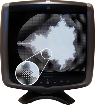
Another advantage of using a VGA monitor directly is that individual pixels are shown very crisply, unlike my video capture card or VGA box which tend to blur the image horizontally. This is shown in the zoomed in part of the above photo.
Generating a video signal for a VGA monitor is easier than generating a composite video signal for a PAL TV, as there are distinct pins for the image data, horizontal sync and vertical sync. One problem I did have, however, is with the length of the vertical sync pulse. I started with a very brief pulse (the same duration as the horizontal sync pulse) which worked fine with my old analogue CRT monitors but didn't work at all with my modern LCD monitor. The documentation I was using for timing information indicated that there were "two scanlines" for vertical sync so I extended the pulse to last for those two frames, which worked on the LCD but didn't on the CRTs. My final compromise has been to assert the vertical sync pin for the duration of a single scanline, which seems to work on all of my monitors.
When connected to a TV two microcontroller pins are used to drive a single load (composite input). When connected to a VGA monitor, however, a single microcontroller pin is used to drive three loads (red, green and blue inputs). I thought it prudent to check the datasheet for the dsPIC before connecting this increased load to the output pin where I was surprised to discover that the maximum source or sink current for each output pin is a measly 4mA — not even enough to drive an LED! I have added a buffer to each video output pin to protect the dsPIC — any buffer capable of sourcing up to 30mA or so should be sufficient (I'm using a 74F125, which can be seen in the bottom right of the above photo). I had previously been occasionally using the video output pins as inputs to check if there is a load on the output or not (such a load would indicate whether a TV or VGA monitor is plugged in or not) but I can no longer do this with the external buffer IC so have had to revise the circuit somewhat. Updated source code featuring the new VGA output code and an accompanying schematic are available for those who are interested!