Updating remapped IO.DLL: The venerable Willem programmer still works on 64-bit Windows 10!
Sunday, 18th August 2019
A few years ago I posted about a way to get the Willem chip programmer to work with modern PCI parallel ports via a DLL that remapped the legacy port addresses to the ones of your modern card (in my case my card is installed at 0xCCD8 instead of 0x378). Since its release I've had several people contact me asking for advice and support, including a few questions about 64-bit support.
Until recently I had been using a 32-bit OS and as such hadn't run into compatibility issues myself. I had replaced the DLL in the zip archive for the project with an allegedly 64-bit-compatible version of the inpout32.dll library that the is used to access the I/O ports but I was unable to test this myself, however it still worked in a 32-bit OS so hoped that it would also work on a 64-bit OS as claimed.
I am now running a 64-bit OS and found myself needing to program a chip with my Willem programmer but was unable to do so, receiving the dreaded Hardware Error: Check Power & connection message. Clearly this DLL was not working as it should under 64-bit Windows!
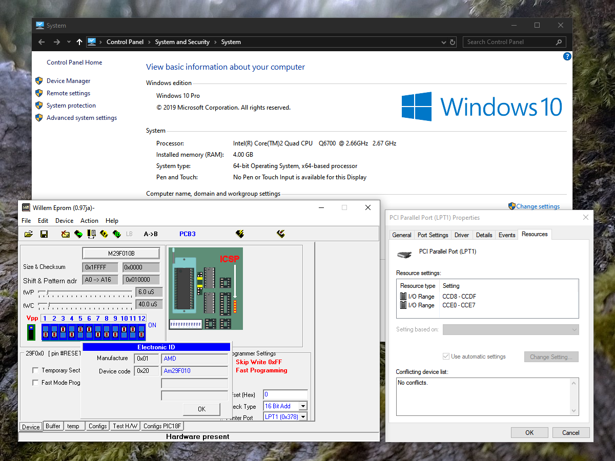
Fortunately, Phil Gibbons of highrez.co.uk has come to the rescue with a 64-bit compatible version of InpOut32 that works perfectly on my 64-bit Windows 10 machine as a drop-in replacement for the old library. I have updated the zip archive containing the software with the working library. For more details and a copy of the Willem programming software please see the Remapped IO.DLL project page.
A temporary solution for 3D games on the Master System without the 3D glasses adaptor
Monday, 29th July 2019
I bought my Sega Master System-compatible 3D glasses almost exactly ten years ago for use in my LCD Shutter Glasses Adaptor project.
More recently I've acquired a CRT television and an actual Sega Master System so I could in theory make use of the glasses as I had originally intended - with Sega Master System games.
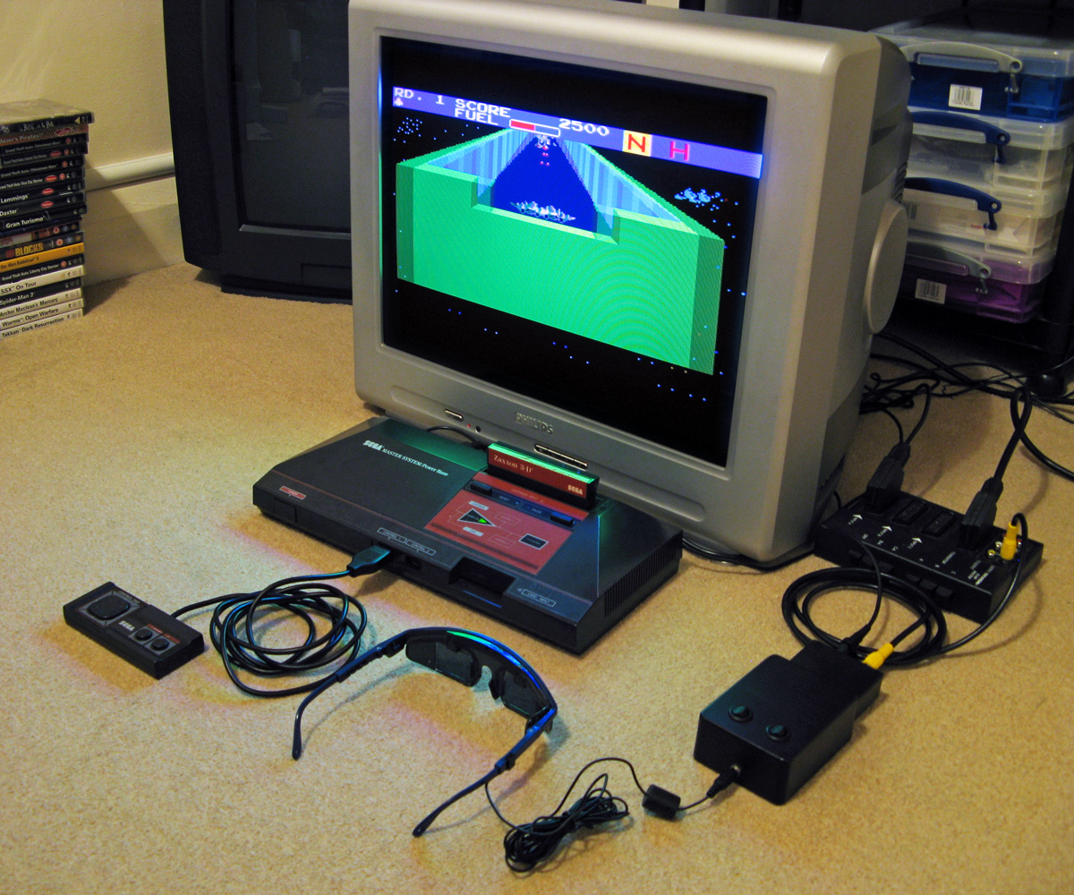
I've been keeping an eye on eBay for the 3D Glasses Adaptor for the Master System. This is a device that plugs into the console's card slot and allows it to drive the glasses with the software controlling which LCD shutter is open and which is closed by writing to the card. Unfortunately, these cards are not too easy to find in the UK and when they do appear they usually came bundled with a broken pair of glasses (it seems very unusual for both arms to still be attached to the glasses, and I've seen a fair few pairs that are cracked down the middle too). I already own some compatible 3D glasses so didn't want to waste money on buying a broken set of original Master System ones!
I did eventually find someone selling a loose adaptor for a reasonable price so bought it and a few games. Zaxxon 3-D was the first to arrive and I was eager to test it out. Without the card adaptor I needed to find an alternative solution, so my thoughts turned to the LCD Shutter Glasses Adaptor I'd built a few years ago.
This is designed to sit between a PC and a VGA CRT monitor and drives the shutter glasses, alternating which LCD shutter is open and which is closed every vertical sync. It can also blank out alternate scanlines, simulating an interlaced signal from a progressive one by blanking odd scanlines on one frame and even scanlines on the next, but this is not useful in our case. The Master System is already alternating complete left and right eye views on its own, so we just need to catch its equivalent of a vsync pulse and feed that into the VGA port on the back of the shutter glasses adaptor.
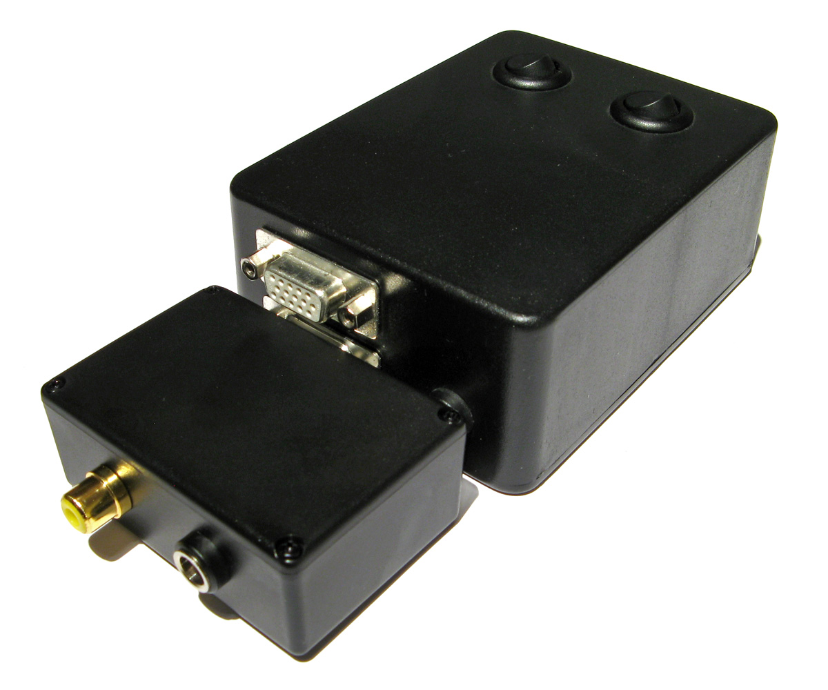
Above is the device I built, attached to the existing 3D glasses adaptor. It has a single composite input which should be connected to the composite output from the console, either via a splitter (if the console is connected to the TV using composite video) or via some sort of SCART breakout box (I'm using the composite video output from my SCART switch box). It also has a power socket which is used to power the circuit inside which is also passed through to the LCD shutter glasses adaptor. The box has a DE-15 connector and 5.5x2.1mm barrel plug on the other side for connections:
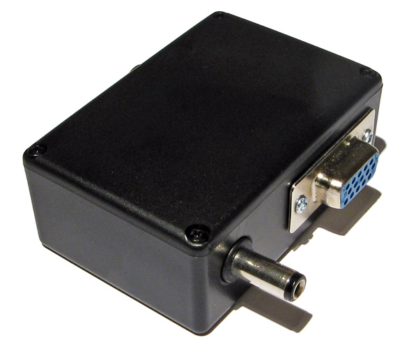
I'd cut the barrel plug off a faulty power supply years ago, I'm glad I kept it as it made the project a much neater solution than it might have other been!
The circuit inside is very simple indeed. As the original adaptor has its own 5V regulator inside and is designed to be powered from a 9V power supply I had to maintain the same convention for this device, so I use a 7805 regulator to convert the incoming voltage to 5V. This powers a textbook example of an LM1881 sync separator circuit - I'm using the reference circuit from the chip's datasheet, connecting the composite video input to the chip's composite video input via a 0.1µF capacitor (without termination as it's assumed the signal is being terminated by the TV) and I use the LM1881's composite sync output and vertical sync output for the VGA connector's horizontal and vertical sync connections respectively.
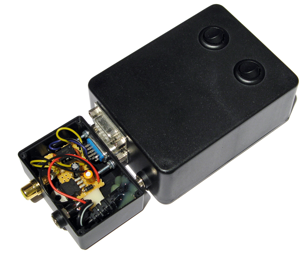
The circuit can be seen above, stuffed in the bottom of the box - along with copious amounts of hot glue to keep the barrel plug in place! How well does it work? Well, the below animation shows two views of the circuit in action, viewed through first one shutter and then the other of the 3D glasses:
This isn't a perfect solution - the Master System expects to be able to explicitly specify which shutter is open whereas in our case we're simply be alternating every frame. This could mean that the eyes are swapped, however there is an eye swap switch on the shutter glasses adaptor to compensate. If the view looks wrong then the switch can be used to correct it, and once that's done as long as the software alternates the views every frame then it should be fine.
I'm certainly happy for now, as it lets me play my 3D games whilst waiting for the console's intended 3D glasses adaptor to arrive in the post.
Fixing the Dreamcast Race Controller's dead zone with a simple microcontroller circuit
Tuesday, 21st May 2019
I recently bought myself a Race Controller wheel for the Sega Dreamcast and was a little disappointed with the way that it performed. I had read reviews online before buying it and some did mention that it didn't handle particularly well but others did mention that it was about the best controller available for the system so I didn't feel it was too risky a purchase.
The issues I have with the wheel stem from its excessively large dead zone – you need to turn the wheel quite far before your car starts to turn, making it feel sluggish and unresponsive.
Fortunately, the wheel hardware is very simple internally – a 100KΩ potentiometer is used to detect the wheel's position and it outputs an analogue voltage to the controller PCB. We can take advantage of that to insert our own circuit between the potentiometer and controller PCB to sample the wheel position, add an large offset to it to push it outside the dead zone and then output that corrected voltage to the stock PCB. This will then cancel out the offset as part of the large dead zone before sending the position to the console.
The video above goes into more detail about how this circuit works as well as illustrating the problem with the stock dead zone. For more information and to download the code and circuit diagram please see the De-Dead Zone product page.
Cheats for the PAL version of Quake on the Sega Saturn
Friday, 25th November 2016
I recently picked up a Sega Saturn and a copy of the technical marvel that is Quake for it.
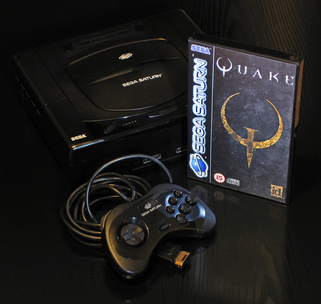
The Saturn is not renowned for being a particularly capable 3D machine and so the fact that Quake runs at all is quite remarkable, let alone as well as it does in Lobotomy Software's version. Rather than port the Quake engine to the Saturn the game uses the SlaveDriver engine, and includes conversions of 28 of the original 32 levels with some minor tweaks to improve performance. It certainly captures the atmosphere of Quake far more faithfully than most console ports of DOOM did to that game, leaving the sound and music intact and retaining the gritty aesthetic of Quake's software renderer.
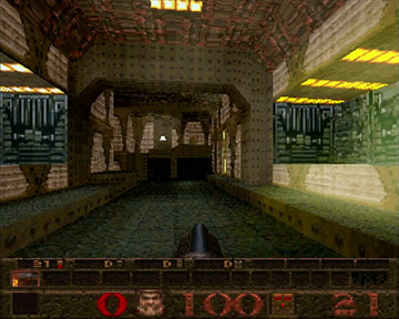
Unfortunately, I'm not very good at it. Even though I could probably complete the PC version's first level in my sleep these days it took me three shameful attempts on the easiest difficulty level to get through it on the Saturn. The controls are somewhat awkward (for example, to aim up you need to hold X and press down on the d-pad) and so I thought that a cheat code or two might help me along until I'd got to grips with the game's controls.
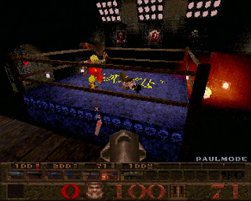
I found a list of cheats on a newsgroup from the game's developer but most of them did not work with my copy of the game, and the few codes that did do something ended up performing the function of a different cheat. For example, invicibility ("Paul Mode") is toggled by highlighting "Customize Controls" then entering RLXYZRLXYZ, but on my copy of the game that toggled "Jevons-Control Mode" instead. These codes matched the ones on various cheat database sites across the Internet, so I was a bit puzzled until I found a forum post with a couple of codes that did work. This is an incomplete set, and it's clear that the PAL version of the game has different cheats to the NTSC-U version. Other sites either mentioned that the PAL version doesn't have cheats at all, or is missing most of them due to being an older version of the engine.
One thing stuck out to me, though - all NTSC-U cheat codes follow the same basic formula of highlighting a particular menu item under "Options", entering a ten button sequence using only the X, Y, Z, R and L buttons, and then seeing a confirmation message on the screen. I assumed that the PAL version would do something similar, and that some table of cheat codes and messages could be found in the executable. I popped the game CD into my PC CD drive and copied the executable file to the hard disk so I could examine it in a hex editor.
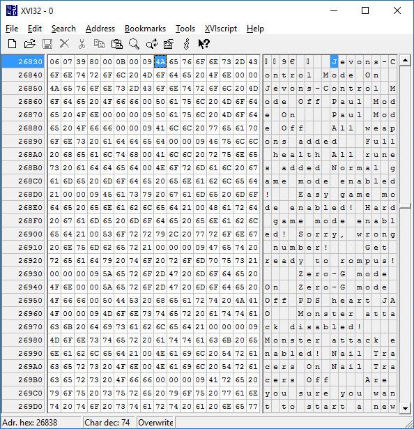
The first thing I did was search for "Jevons-Control" which identified it at the top of a list of other cheat-related messages such as "All weapons added" or "Nail Tracers On" which made me hopeful that the other cheat codes were present in the PAL version of the game. Some cheats in the NTSC-U version (such as those relating to rain or cluster bombs) didn't seem to have an equivalent message in the list of strings here so these were presumably missing in the PAL version, but at least I knew I was on the right track.
At this point, I had two button sequences that I knew worked - RLXYZRLXYZ and LRLLZYXZYX. I hoped that these codes might be found in the game's executable, but of course didn't know how they'd be represented. At first I assumed each code would be a ten byte sequence, with one value for 'R', one value for 'L', another for 'X' and so on and so forth. As the two known cheats repeated buttons (for example, LRLLZYXZYX has L three times) it would be possible to see if a particular sequence of bytes followed the same pattern as the cheat code (for example, with LRLLZYXZYX the first, third and fourth bytes would need to all have the same value to represent 'L', and that value could not appear anywhere else in the ten byte sequence). With that in mind I wrote a program that scanned through the entire binary from start to finish, checking to see if either of the two codes could be found. Neither could, so I changed the program to instead assume that each button's value would be stored as a sixteen-bit word. Still no luck, but as the Saturn is a 32-bit system I again increased the size of each button in the sequence to try 32-bit integers and found two matches for the two codes.
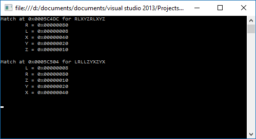
Not only were both sequences found, but both used the same values for the buttons (e.g. L is 0x00000008 in both sequences) and both were near each other in the binary. This seemed like the place to look, so I put the lower address value into the hex editor to see if there were other sequences nearby.
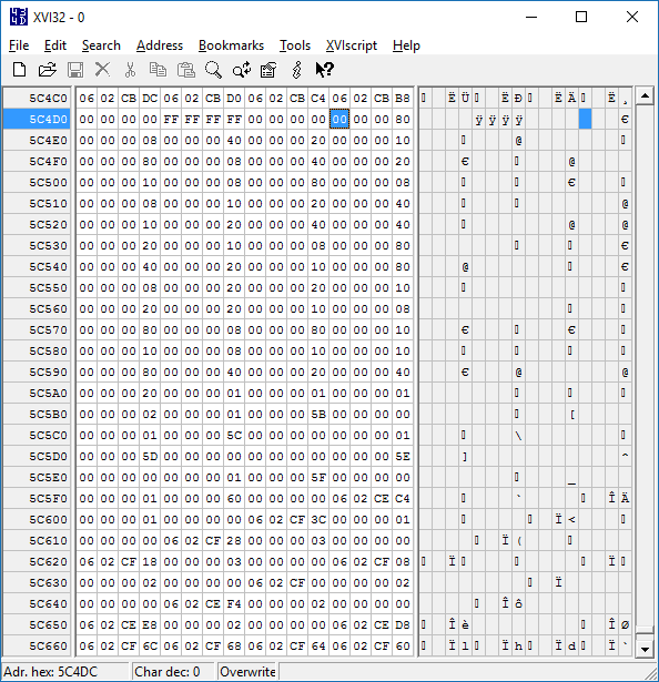
Now that I knew where the cheat codes were and how to map each value to a button name I could work through the binary, check to see if each sequence of ten 32-bit integers all matched known button values and if so output the sequence. This gave me three additional sequences for a total of five.
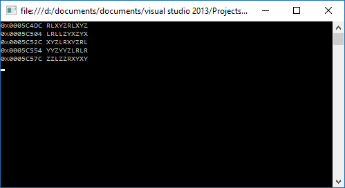
Now I could take those five sequences, try them in the game and match them to the known NTSC-U sequences. Most of the cheat codes sequences are used more than once, changing behaviour depending on which menu item was highlighted when they were entered. Comparing the effect of certain codes in the PAL version against what the NTSC-U version was known to do produces the following table:
| NTSC-U | PAL |
|---|---|
| RRLRXYZXYZ | RLXYZRLXYZ |
| RLXYZRLXYZ | LRLLZYXZYX |
| RXLZLRYLRY | XYZLRXYZRL |
| RYLYXYZXYZ | YYZYYZLRLR |
| RZLXYLRYLR | ZZLZZRXYXY |
I'm not sure why the PAL version uses different cheat code sequences, but it is an earlier version of the game and they are also quite a bit easier to enter on the console so maybe it was decided that players needed to work harder to take advantage of their cheat codes. There are a few other NTSC-U cheat code sequences that don't match up with the PAL version, but these are for cheats that seem to be missing equivalent strings (such as the previously mentioned rain or cluster bomb cheats) so I reckon they were not yet added to the PAL version.
For the sake of completeness, here is a list of cheats that work in the PAL version of Quake. All need to be entered by pausing the game, highlighting a particular item in the Options menu and then entering the cheat code as quickly as you can. Some cheats also require you to stand in a particular place in a map or to have collected certain items first; these are noted where appropriate.
| Name | Menu | Cheat |
|---|---|---|
| Paul Mode (Invincibility) | Customize Controls | LRLLZYXZYX |
| All Weapons | Customize Controls | XYZLRXYZRL |
| Full Health | Customize Controls | YYZYYZLRLR |
|
All Runes Stand in the area where the first rune can be picked up in "The House of Cthon". |
Customize Controls | ZZLZZRXYXY |
| Jevons-Control Mode (3D Control Pad) | Customize Controls | RLXYZRLXYZ |
|
Level Select You must either have all four runes or be standing on the right hand side of the flat part of the bridge over the lava in the "Entrance" level. |
Reset to Defaults | RLXYZRLXYZ |
| Restart Level | Reset to Defaults | LRLLZYXZYX |
| Normal Difficulty | Music Volume | RLXYZRLXYZ |
| Easy Difficulty | Music Volume | LRLLZYXZYX |
| Hard Difficulty | Music Volume | XYZLRXYZRL |
|
Show Credits Stand on the right hand side of the bridge under the round stained glass window in "Castle of the Damned". |
Stereo | RLXYZRLXYZ |
|
Show Special Credits Stand in the secret underwater cave containing the Megahealth and Nails in "Gloom Keep". |
Stereo | LRLLZYXZYX |
|
Quake Wrestling Stand either at the Quad Damage in the secret area opened by jumping into the overhead light in "The Sewage System" or in the suspended cage half way through "The Tower of Despair". |
Stereo | XYZLRXYZRL |
| Zero-G Mode | Lookspring | RLXYZRLXYZ |
| Monster Attack | Auto Targeting | RLXYZRLXYZ |
| Nail Tracers | Auto Targeting | LRLLZYXZYX |
If there are still people out there struggling through the PAL version of Quake on the Sega Saturn, maybe these cheat codes will come in handy!
Repairing a PlayStation controller to USB adaptor
Saturday, 20th April 2013
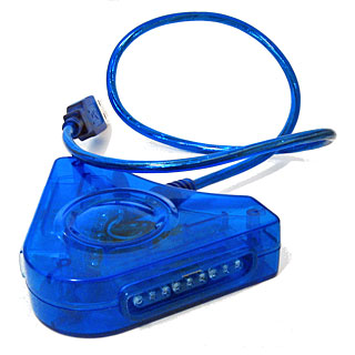
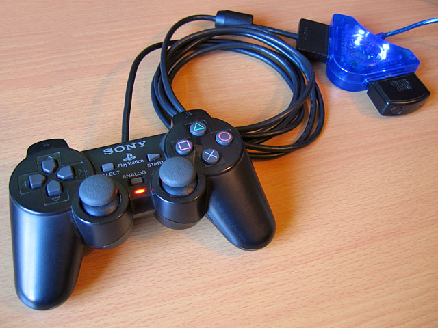
I recently purchased an inexpensive PlayStation controller USB adaptor for my PC. Several reviews confirmed that it was compatible with the controller's analogue joysticks so I thought it would be what I was after. Life is rarely that easy with cheap electronics, unfortunately!
When it arrived I plugged it in and Windows installed the appropriate HID drivers for it automatically, but as much as I waggled the joysticks on a connected DualShock 2 controller the axis preview in Control Panel remained resolutely in the zero position. PlayStation controllers have an "Analog" button that can be pressed to toggle between digital and analogue modes, but any attempts to press this resulted in the "Analog" light briefly flashing before immediately switching off again.
Thinking it may be a driver issue I tried to install the drivers from the mini CD that had been included with the adaptor. My PC could not read the disc (it appeared to be scratched, and was not very well protected in postage) so I hunted around online until I found a package that worked using the device's USB ID (VID_0810&PID_0001). This enabled the controller's rumble/vibration feature, but I still couldn't get analogue input to work. Thinking that if one driver package could add vibration support, another might add analogue support I contacted the Amazon seller to ask them if they could send me a copy of the correct drivers - they instead chose to send me a whole other unit in the post.
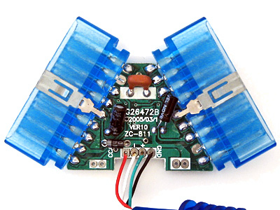
In the meantime, I experimented with another controller plugged into the adaptor. I was surprised to find that with two controllers plugged in at once I could enable analogue mode on one of the controllers. This made me think there could be a power issue - the second controller increased the capacitance across the power supply, which would make it more resilient to voltage spikes and reduce ripple that could be causing the controller to reset out of analogue mode. This was further confirmed by plugging the adaptor with a single controller into a powered USB hub - in this scenario the controller would only leave analogue mode when vibrating. I checked the power supply pins on the controller ports and was very surprised to see that there was apparently nothing connected to pin 5, which is supposed to deliver +5V to the controllers. At this point I decided to dismantle the adaptor to see what was going on.
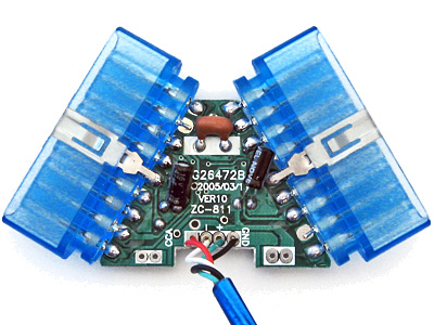
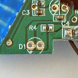
On the inside of the adaptor I could see that several components had been omitted. This could be to blame on cost-cutting measures (e.g. the LEDs D1 and D2 which are purely cosmetic) but the removal of D3 puzzled me the most - this diode is connected between USB VCC and the controller port pin 5, and is presumably responsible for providing power to the connected controller. I put this down to an oversight at the factory, and soldered a 1N4001 rectifier diode in the marked place.
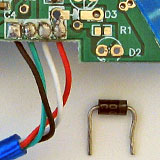
The above image shows a close-up of the place the missing diode should appear - D3 is indicated by a silk-screened diode symbol. Unsurprisingly the 1N4001 silicon diode has far superior characteristics to the silk-screen diode it replaced.
With the diode in place both controller ports started working flawlessly, even allowing me to use a wireless Guitar Hero controller receiver (though not the whammy bar - Guitar Hero controllers lack the "Analog" button to manually enable the analogue mode and instead rely on the PlayStation to enable it via software). Whilst I had the soldering iron out I thought I should add the missing LEDs, once again using the existing markings to establish the correct polarity:
If the markings are unclear, the anode (+) is always to the left when viewing the bottom of the circuit board when the other markings are upright.
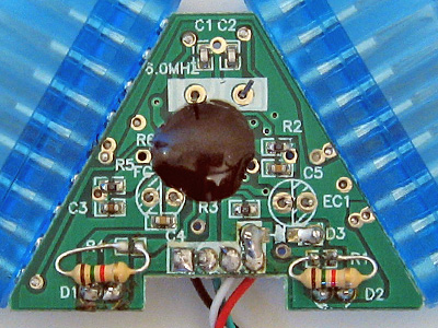
As the enclosure is blue and I seem to remember some fuss being made of the PlayStation 2's blue LED when it first came out I opted to use two blue LEDs with 1K5 resistors. I do not have any surface-mount resistors but through-hole ones fit quite easily though they can be a little fiddly to solder down.
When the replacement adaptor arrived in the post I was surprised to see that (once again) the diode D3 was missing and it demonstrated the same problems as the other one I'd fixed. I find it unlikely that the same mistake could be made twice, so this seems to be a genuine cost-cutting measure. Microcontroller I/O pins often have an internal protection diode between them and the positive power supply, which is how I assume the circuit works at all when the controllers are left unpowered - a small amount of current flows from the I/O (data) pins to the positive rail via these protection diodes, which is just enough to let the controller work in digital mode but once they draw more current (e.g. when sampling analogue inputs or driving the vibration motors) the voltage droops far enough for the controller to reset and leave analogue mode.
With these fixes in place I now have two working PlayStation USB adaptors for the price of one (and two 1N4001 diodes). I'm still rather perplexed by why there's such a blatent flaw in the hardware, but it is at least an easy fix which is why I've written it up. In summary: if your cheap PlayStation to USB adaptor ("Twin USB Vibration Gamepad", "Twin USB Joystick") is not working correctly, unscrew it and see if D3 is missing. If it is, solder a 1N4001 or similar diode between the two holes left for that purpose.