Various calculator-related updates: BBC BASIC, Vinegar, Telnet 83, Brass and Latenite
Sunday, 14th June 2026
My original TI-83 Plus feels like it's on its last legs. I suspect there's some issue with the flash memory, and I've already had to wipe its certificate page using the BootExec utility that exploits a buffer overflow in the link routines to get an operating system back on it. Even though it's working for now, I'm somewhat wary of installing flash applications on it.
Recently, however, someone contacted me to let me know that there was a bug in the TI-83 Plus version of Richard Russell's BBC BASIC that I'd put together a few years ago. It turns out that on more recently-manufactured TI-84 Plus calculators uses a new LCD driver which modifies the data pointer when reading back the status register. The BBC BASIC host interface I'd put together polls the busy flag in this status register, and so the display was corrupting on these new calculators as writes to the LCD memory were not going to the correct address.
It was a reasonably easy fix (replacing my own LCD busy test with a call to the one provided by the calculator's operating system), but not one I could test myself as I don't own a TI-84 Plus. I also wanted to check that there weren't any regressions with the fix, but I didn't want to risk damaging my TI-83 Plus further by reinstalling the flash application on it.
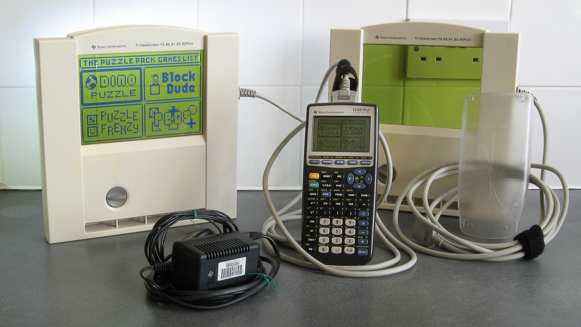
I did find the above TI-83 Plus Silver Edition calculator on eBay, though, for a good price – and it's the ViewScreen model! This has a special socket on the back of the calculator that lets you plug in a large external LCD (it came with two of them) which is designed to be used on an overhead projector so a teacher can demonstrate using the calculator to their students. I'd previously experimented with a project that displays the calculator's screen on a TV, but that captures a screenshot over the calculator's link port so is slow, requires a button to be pressed to update the image and only works in situations where the OS is idly waiting for a keypress. The ViewScreen taps into a buffered copy of the signals sent to the calculator's LCD driver, so will automatically and immediately show a copy of what's on the calculator's own screen.
Now that I had a TI-83 Plus Silver Edition I installed BBC BASIC on it, saw that the LCD fix had worked and not broken anything else, but also encountered a few other bugs that I'd not noticed before which I've also fixed:
- Pressing non-printable keys (e.g. cursor keys) in INKEY no longer slows CPU down to 6MHz until the app is restarted.
- Pressing Clear in INPUT statements now clears the whole input line instead of inserting a CHR$27 into the line.
- The On key only triggers escape when pressed. On the Silver Edition it was triggering when released as well.
These updates have been uploaded to the project page on this site, the GitHub page and ticalc.org.
Now that I had a shiny new calculator, I thought I'd try installing some other old programs on it to see how well they worked. One of these was Vinegar, a CHIP-8 and SCHIP 'emulator'/interpreter. I soon found that this also had an LCD bug on the TI-83 Plus Silver Edition, as enabling the "96x64 SCHIP mode" (which scales the 128×64 native resolution of SCHIP games down to the calculator's 96×64 display instead of cropping it) would erroneously switch the LCD driver into "6 bits per column" mode after a few seconds of play instead of the intended "8 bits per column" mode, corrupting the display.
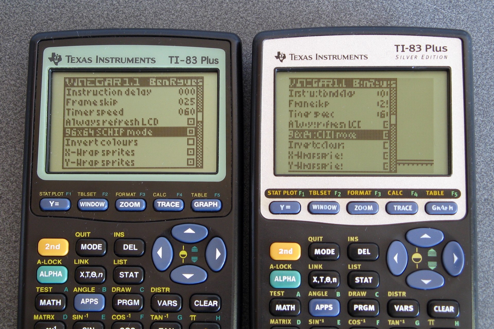
How the options menu should appear (left) versus how it appears on the Silver Edition (right) due to a bug.
This project had some very old code and had never been checked into source control so I set it up on GitHub, combined the copy of the source code I had on my local machine with the source code that was publicly available for download and fixed the LCD bug. I also found and fixed a memory leak bug that occurred if no CHIP-8/SCHIP programs ("ROMs") were installed on the calculator and added a couple of keyboard shortcuts to control the display. These changes are available in release 1.2 on the main project page, the GitHub page and ticalc.org.
The next bug I spotted was in Telnet 83. I didn't originally write this particular program, but it is included as part of the TIWiFiModem project where I've already made some bug fixes and improvements. When trying to use it to set up my TIWiFiModem with my new wireless access point I discovered that I couldn't type in the password as some of the keys were not being mapped correctly. I'd previously corrected other key mapping bugs in this program but must have missed a couple, so these are now fixed. There isn't an official release for this project but the compiled .8xp is checked directly into the repository so can be downloaded from there.
I use my old Brass assembler to build the Telnet 83 project. Some other people do still use this from time to time and so I decided it would be best for the community if the source code was available, no matter how embarassingly poorly-written it was. To this end I set up a GitHub repository a few years ago, but as the code had never been checked into source control before then there was no accompanying history. I did have a few old backups and so imported them into the repository in date order, but as these backups were taken around 20 years ago with no notes as to what I was thinking at the time it's all a bit of a mess!
As this is not intended to be an actively-developed project I don't plan to make too many changes to it, but I have fixed a couple of bugs along the way. Notably, operator precedence is handled more correctly now (operators with the same precedence, such as * and /, are now evaluated from left to right whereas previously * had higher precedence than /). When working on Telnet 83 I also found that if data overlaps in the output binary the reported address range was incorrect and also poorly-formatted, and this has now been fixed too:
Brass Z80 Assembler 1.0.5.4 - Ben Ryves 2005-2023 ------------------------------------------------- Assembling... Pass 1 complete. (310ms). Pass 2 complete. (84ms). Writing output file... Warning: Data overlap between$14930-$14930. ← Now shows the correct value '$AB9D' Errors: 0, Warnings: 1. Done!
String literals were also handled very oddly, and I've slightly improved this and added extremely rudimentary expression parsing on string, so #include "page" + pagenum + ".asm" now works as you might expect. I've filled in some of the missing gaps in the documentation, too; updates can be downloaded from the Brass page on this site or the GitHub repository.
An even more ancient development tool that I put together was Latenite, an IDE designed to be used for Z80 development. I hadn't used this myself in years (preferring to use Visual Studio Code as an editor and the Brass 3 Project Builder to build the code and launch a debugger) but Vinegar was set up to use this (including a project file, build scripts and debug scripts) so I thought I'd give it a go. Unfortunately, it really didn't work – the files I had on my local development copy didn't match what was in the publicly released zip files, and neither worked with what Vinegar was expecting.
Again, I set up a GitHub repository for the project and tried to piece together a working code base using the files I had locally, the files that had been publicly released and what I could remember of what had gone on twenty years before.
The solution contained a series of projects for tools (an 8xp "linker", a TASM error processor and a WLA-DX error processor) that aren't included in later releases of the software. I suspect these are remnants of the project from before Brass became the bundled assembler. I have added the Brass repository as a submodule to the project so that it can be built alongside Latenite, and that will hopefully help keep things in sync.
A notable sticking point was a conflict in the PindurTI-based debugging system. There appear to be two different versions, with different debug scripts and executable names. The older "PTIDebugger" was a project in the Latenite solution I had locally, and is what the Vinegar project was looking for, however the bundled project template for TI-83 (Plus) development uses a new executable called "PindurTI Debugger" and set of debug scripts with incompatible file names and I had no record of its source code anywhere.
Fortunately, the old Latenite interface for this debugger is still present in the PindurTI debugger that's part of the Brass 3 repository, so I suspect this was originally developed for Latenite before being incorporated in the Brass 3 project. I can't currently use this as a submodule of the Latenite project as it has a dependency on Brass 3 (and I don't want to have to bundle the whole of Brass 3 in the same project, as it's not relevant) so I just copied the code over and removed the Brass 3 bits.
PindurTI is an emulator developed by the legendary Patai "cobb" Gergely, not that you'd know it from the lack of attribution in Latenite or my other development tools. Similarly, calculator shells were bundled directly for debugging purposes without mentioning their authors or including their documentation, just a raw binary. For the most part image resources used in the IDE were nicked directly from Windows XP or Visual Studio, too. This is all very naughty! Whilst I don't really intend to pick up development on Latenite again, beyond fixing some of the more obvious bugs, I would at least like to try to remedy this. I've already replaced the image resources with new icons and now provide links to the calculator shell documentation from within the IDE. There's still a way to go before I'm happy with this, though.
A comparison of the old icons (top) compared to the new icons (bottom).
I don't expect anyone to be still using this development tool, but in case there are old projects out there that were assembled using it then in the interest of making sure they can still be built in the future I think it's worth making sure the source code is available.
All of this relates to calculator programming and the place where I used to share all of this was the MaxCoderz forum. This has had very little traffic for the past few years, but if you were one of the few people looking for it you might have noticed that until very recently it was unavailable. This was due to bots very aggressively scraping the content, causing phpBB to insert millions of rows onto the session table on the database – this one site that had virtually zero legitimate traffic ended up slowing down the entire server to a crawl a few times per day, and though I did at first selectively block the bots it ended up being a very tedious game of Wack-a-Mole and so I ended up taking down the whole forum.
Nobody had complained about the site being down, but in the interest of keeping sites online for historical interest I have restored the site and it's now protected with CloudFlare. This is not something I'm too happy about doing, but I'd rather have a site accessible via CloudFlare than not accessible at all.
One thing I have noticed is that this site is very poorly-equipped for distributing information about updates, with so many projects being scattered across different (and poorly-maintained) sections of the site. I am currently working on overhauling this site and shifting it onto a new platform, but one of the key requirements is to not break any of the existing links or content so it'll take a bit more work to get it ready.
Calculating the approximate phase of the moon on a range of devices
Tuesday, 7th April 2026
Calculating the phase of the moon always struck me as a fun little program for a calculator, and with the current Artemis II mission it seemed like as good a time as any to look at a few example programs for this on a range of different calculators and pocket computers.
Sharp PC-1211

I copied the following program from the book 119 Practical Programs for the TRS-80 Pocket Computer and it forms the basis of most of the subsequent programs:
  100 "MOON"INPUT "DATE M?",M,"D?",D,"Y?",Y: GOSUB "DJ"
  110 M=(J+4.867)/29.53058:M=2*(M-INT M)-1:N=ABS M
  120 USING "##.##": PRINT "MOON LIT ABOUT ";N
  130 Z$="NEW": IF M>0 LET Z$="FULL"
  140 PRINT "HEADED FOR A ";Z$;" MOON.": END
  900 "DJ"J=INT (365.2422Y+30.44*(M-1)+D+1):N=M-2+12*(M<3)
  905 Z=Y-(M<3):E=INT (Z/100):Z=Z-100E
  910 W=INT (2.61N-.2)+D+Z+INT (Z/4)+INT (E/4)-2E
  915 W=W-7*INT (W/7):X=J-7*INT (J/7)
  920 J=J-X+W-7*(X<W)+1721061: RETURN
The program has two parts; the first is to convert a date from its year, month and day components into a Julian day number which it does via the subroutine DJ. It then calculates the phase of the moon by adding an offset (4.867 in this case) and dividing by 29.53058, the length of the synodic month (lunar cycle) in days. The fractional part of the result of this calculation corresponds to the phase of the moon, and by multiplying by two and subtracting one you can get a value roughly corresponding to how illuminated the moon is on a particular date and whether it's waxing (heading for a full moon) or waning (heading for a new moon).
Incidentally, the program listing printed in the book does have a bug: line 130 just checks IF M instead of IF M>0, and so the program will nearly always report a waxing moon (heading for a full moon). This is corrected in the version of the code shown above.
Sharp PC-1500

The next page of the book where I copied the PC-1211 listing from showed a graphical representation of the moon's phase which I thought would be fun to replicate, though as the PC-1211's printer doesn't support graphics it would be a very crude representation indeed. Fortunately, the PC-1500's plotter allows for graphical output, so I added an optional plotting routine to the above program as well as some other niceties like automatically populating the month and day fields with the value from the real-time clock:
   30 T=TIME :Y=2000:M=INT (T/1E4):T=T-M*1E4:D=INT (T/1E2)
   40 L=-50
   50 WAIT 0
   60 CLS : PRINT "Year (";STR$ Y;") ";: INPUT Y
   70 CLS : PRINT "Month (";STR$ M;") ";: INPUT M
   80 CLS : PRINT "Day (";STR$ D;") ";: INPUT D
   90 CLS : WAIT
  110 J=INT (365.2422*Y+30.44*(M-1)+D+1)
  120 N=M-2+12*(M<3)
  130 Z=Y-(M<3)
  140 E=INT (Z/100)
  150 Z=Z-100*E
  160 W=INT (2.61*N-.2)+D+Z+INT (Z/4)+INT (E/4)-2*E
  170 W=W-7*INT (W/7)
  180 X=J-7*INT (J/7)
  190 J=J-X+W-7*(X<W)+1721061
  210 P=(J+4.867)/29.53058
  220 P=2*(P-INT P)-1
  230 N=ABS P
  240 Q=INT (N*100+.5)
  250 CLS : PRINT "Moon lit about";Q;"%"
  260 Z$="full": IF P<0 LET Z$="new"
  270 CLS : PRINT "Headed for a ";Z$;" moon."
  290 IF PEEK &A000<>&C0 END
  300 WAIT 0:P$="Y": PRINT "Print output (Y/N) ";: INPUT P$
  310 IF P$<>"Y" END
  320 "MPRINT" CLS : PRINT "Latitude (";STR$ L;") ";: INPUT L
  330 IF L<-90 LET L=-90
  340 IF L>90 LET L=90
  360 CLS : PRINT "Printing...": WAIT
  380 M$=STR$ M: IF M<10 LET M$="0"+M$
  390 D$=STR$ D: IF D<10 LET D$="0"+D$
  400 TEXT : CSIZE 3: LPRINT STR$ Y;"-";M$;"-";D$
  410 GRAPH : GLCURSOR (216/2,-216/2+15): SORGN :R=108: DEGREE
  420 C=9: FOR A=0 TO 360 STEP 6
  430 LINE -(R*SIN (A),R*COS (A)),C
  440 C=0: NEXT A
  450 V=N*2:C0=9:C1=0
  460 IF P>=0 LET V=2-V:C0=0:C1=9
  470 FOR S=1 TO 2:C=9
  480 FOR I=-R TO R STEP 8
  490 XO=I*COS (-L):YO=I*SIN (-L)
  500 W=√(R*R-I*I)
  510 XN=W*SIN (L):YN=W*COS (L)
  520 X=XO-XN+V*XN:Y=YO-YN+V*YN
  530 IF S=1 LINE -(X,Y),C:C=0
  540 IF S=2 GLCURSOR (XO-XN,YO-YN): LINE -(X,Y),C0: LINE -(XO+XN,YO+YN),C1
  550 NEXT I: NEXT S
  560 GLCURSOR (-216/2,-216/2-25): SORGN
  710 TEXT : CSIZE 2: LPRINT "Moon is lit about"
  720 LPRINT STR$ Q;"% and headed"
  730 LPRINT "for a ";Z$;" moon."
  740 LF 3: END
The program also prompts for latitude to rotate the drawing appropriately – the moon appears to fill with light from the right to the left in the Northern hemisphere, from top to bottom at the equator and from the left to the right in the Southern hemisphere.
HP-12C

This calculator is really designed for financial applications but it is keystroke programmable and so a phase of moon calculation program would be a good learning project. Fortunately it can already calculate the number of days difference between two dates, so that would save having to write a program to calculate the Julian day number.
| Step | Key | Display | Comment |
|---|---|---|---|
| 01 | ENTER | 36 | Enter the current on-screen value onto the stack. |
| 02 | 1 | 1 | Enter "1.012" (1st January 2000). |
| 03 | . | 48 | |
| 04 | 0 | 0 | |
| 05 | 1 | 1 | |
| 06 | 2 | 2 | |
| 07 | g ΔDYS | 43 26 | Calculate number of days between 1st January 2000 and the submitted date. |
| 08 | CHS | 16 | Change sign to get the number of days after 1st January 2000. |
| 09 | 2 | 2 | Enter "20.195" (offset to 21st January 2000, 04:41). |
| 10 | 0 | 0 | |
| 11 | . | 48 | |
| 12 | 1 | 1 | |
| 13 | 9 | 9 | |
| 14 | 5 | 5 | |
| 15 | - | 30 | Subtract to get the number of days since the full moon. |
| 16 | 2 | 2 | Enter "29.53059" (synodic month, lunar cycle duration in days). |
| 17 | 9 | 9 | |
| 18 | . | 48 | |
| 19 | 5 | 5 | |
| 20 | 3 | 3 | |
| 21 | 0 | 0 | |
| 22 | 5 | 5 | |
| 23 | 9 | 9 | |
| 24 | ÷ | 10 | Divide to get lunar phase. |
| 25 | g FRAC | 43 24 | Extract the fractional part. |
| 26 | 1 | 1 | Add 1. |
| 27 | + | 40 | |
| 28 | g FRAC | 43 24 | Extract fractional part again (corrects negative values). |
| 29 | 2 | 2 | Multiply by 2 (value in range 0 to 2). |
| 30 | × | 20 | |
| 31 | 1 | 1 | Subtract one (value in range -1 to +1). |
| 32 | - | 30 | |
| 33 | ENTER | 36 | Enter result onto the stack (Y). |
| 34 | 1 | 1 | Enter 1 into X. |
| 35 | x⇔y | 34 | Swap so X=result, Y=1. |
| 36 | %T | 23 | Express X (result) as a percentage of Y (1). |
| 37 | g GTO 00 | 43,33 00 | End program. |
Dates on the HP-12C are represented as decimal values, either MM.DDYYYY or DD.MMYYYY depending on the current calculator mode. To keep things simple, rather than calculate the correct Julian day number the number of days since the first of January 2000 is used as the reference as this can be represented as 1.012 in either mode.
This change of date meant that the offset from the Julian day number (previously 4.867) could no longer be used. As the range of moon phases (0 to 1) are mapped to being from full to full (-100% to +100%) the 0 reference value also needs to be a full moon. I found a list of moon phases for the year 2000 which put a full moon at 04:41 on 21st January, so the offset was set to 20.195 – 20 days after the 1st January is the 21st, and 04:41 is (4+(41/60))/24=0.195 hours into the day.
One other very minor change from previous programs is the use of 29.53059 as this is a closer approximation than 29.53058, but in the grand scheme of things it doesn't make much difference to the accuracy. The program can be run by typing in the desired date (e.g. 7.042026) and pressing the R/S key.
Casio fx-3800P

This is another keystroke programmable calculator, though life is made a little more difficult for us compared to the HP-12C as it doesn't have a built-in function to compute the number of days between two dates. One complication with adapting date computation algorithms to scientific calculators is that they often lack functions to truncate values to integers, and even if they do have a way to round a number (e.g. by switching to a mode that only shows a certain number of fixed decimal places and using a "modify" key to convert the displayed number to the stored one) they sometimes don't allow mode switches mid-program.
Fortunately, the Casio fx-3800P will store mode changes in its programs. Even better, you can switch between different numerical bases and the value will be truncated (not rounded) without raising an error which is the behaviour we want when handling date calculations, and when in this BASE-n mode calculations are carried out using integer division and multiplication which suits the algorithm perfectly.
The program is split into two parts: PROG I converts a date (stored in constant registers K1=year, K2=month, K3=day) into the Julian day number and stores the result in the memory register M. The second part, PROG II, converts the Julian day number stored in M into the approximate phase of the moon.
PROG I is adapted from Julian Day Numbers by Bill Jefferys, and is as follows:
| Keys | Comment |
| 1 Kin - 1 | Subtract 1 from year. |
| 12 Kin + 2 | Add 12 to month. |
| 15 - Kout 2 = | Check if month is in valid range. |
| x>0 | If not, loop back to start. |
| 1 Kin + 1 | Add 1 back to year. |
| 12 Kin - 2 | Subtract 12 back from month. |
| Kout 1 + 4716 = × 365.25 = | Base of Julian day number based on current year. |
| MODE 1 DEC MODE 0 Min | Truncate to an integer and store in M. |
| Kout 2 + 1 = × 30.6001 = | Offset Julian day number by value from month number. |
| MODE 1 M+ | Truncate to an integer and add to M. |
| Kout 1 ÷ 100 = M- | Account for centuries not being leap years. |
| Kout 1 ÷ 400 = M+ | Account for special case century leap years. |
| Kout 3 M+ | Offset Julian day number by the day of the month. |
| Kout 2 ÷ 13 = Kin + 1 | Restore original year if we shifted it back. |
| Kout 2 ÷ 13 × 12 = Kin - 2 | Restore original month if we shifted it forward. |
| MODE 0 | Switch back to COMP for floating point. |
| MR - 1522.5 = Min | Subtract offset to get Julian day number. |
PROG II is somewhat simpler, and follows the same sort of logic as previous programs:
| Keys | Comment |
| MR + 5.867 = ÷ 29.53059 = | Add Julian day offset and divide by synodic month. |
| Kin 4 | Store phase in K4. |
| MODE 1 + 0 = MODE 0 | Truncate phase to an integer. |
| Kin - 4 | Subtract from K4 to get fractional part of phase. |
| 200 × Kout 4 - 100 = | Convert to range -100 to +100. |
As mentioned above the programs make fairly heavy use of mode switching to truncate values to integers. Program flow control is very limited on these programmable scientific calculators, usually only permitting a jump back to the start of the program based on a certain condition – hence the slightly clumsy month/year adjustment at the start and end of PROG I.
The Julian day number calculation returns a value that is 0.5 smaller than the value returned by the PC-1211 program that was the basis for most of the other programs (e.g. for 7th April 2026 the Bill Jefferys algorithm returns the correct 2461137.5, the algorithm in the PC-1211 program returns 2461138). To compensate for this the offset used to calculate the current phase of the moon is made 1 larger; not 0.5, as through some experimentation a value of 1 produced results that more closely matched a lunar phase calculator I found elsewhere.
That said, none of the programs above line up particularly well with any other lunar phase calendar, and if you search through days to find when the new moon, full moon and quarters are based on the values closest to 0%, 50% and 100% you'll often find yourself a day off to one side or the other. A more accurate program would be useful, which brings me to the final and most sophisticated program.
Sharp PC-1251

When leafing through old issues of La revue des Sharpentiers, a French publication about all things Sharp from the 1980s, I found an interesting program for the PC-1261: Les phases de la lune.
This program can produce an accurate calendar of moon phases, showing the dates and times of the new moon, full moon and quarters on a month-by-month basis. The article goes into detail about how it works, and I was keen to try it, but unfortunately I do not own a PC-1261! The closest machine I have is the PC-1251, as that matches the 24-column display and printer. However, there are some troublesome differences; the PC-1251 only has a single-line display, and so the PC-1261's code would need to have anything referring to the second line of the display adjusted or removed. A more significant issue is variable names; the PC-1261 supports two-character variable names, whereas the PC-1251 only supports a single character for its variable names.
I typed in the PC-1261 program and made a list of the two-character variable names it used along with a list of the single-character variable names it does not use. There were too many two-character names to fit in the space left over, so I had to make some further adjustments to reduce variable usage such as reusing the same variable in different places for different purposes or reordering code to avoid needing to store a value in an intermediate variable.
    1 "A": PRINT =LPRINT : GOTO 5
    2 "Z": PRINT =PRINT : GOTO 5
    3 REM PHASES DE LA LUNE*J.HERY D APRES J.MEEUS* EDI.20/11/85
    5 CLEAR : WAIT 100: DEGREE :U=0: DIM M$(12)*9,L$(7)*2: RESTORE
    7 FOR I=1 TO 12: READ M$(I): NEXT I
   10 FOR I=1 TO 7: READ L$(I): NEXT I
   20 PRINT "**PHASES DE LA LUNE**"
   25 INPUT "ANNEE ? ";Y: INPUT "NO MOIS OU AN ? ";S$:Z=Y
   30 G=1: IF Y<1583 LET G=0
   35 USING "#####": PRINT "AN:";Y: IF S$<>"AN"PRINT "MOIS: ";M$(VAL S$)
   40 PRINT " PH.   DATE    TU.(H.M)": PRINT ":--:----------:--------:": WAIT
   45 K=INT ((Y-1900)*12.3685)
   50 T=(Y-1899.5)/100
   60 I=2415020+29K
   65 L=.0001178TT-.000000155TTT
   70 L=L+.75933+.53058868K
   75 L=L+.00033*SIN (166.56+132.87T-.009173TT)
   80 L=L-.000837T-.000335TT
   85 N=.08084821133K
   90 N=360*(N-INT N)+359.2242
   95 N=N-.0000333TT
  100 N=N-.00000347TTT
  105 O=.07171366128K
  110 O=360*(O-INT O)+306.0253
  115 O=O+.0107306TT
  120 O=O+.00001236TTT
  125 V=.08519585128K
  130 V=360*(V-INT V)+21.2964
  135 V=V-.0016528TT-.00000239TTT
  140 K=4*(VAL S$-1): IF S$="AN"LET K=0
  145 FOR K=K TO 53
  150 J=I+7K:F=L+.38264717K
  160 P=N+K/4*29.10535608
  165 Q=O+K/4*385.81691806
  170 W=V+K/4*390.67050646
  180 IF U=0 OR U=1 GOSUB 300
  185 IF U=.5 OR U=1.5 GOSUB 340
  190 F=F+.5/1440
  195 J=J+INT F:F=F-INT F
  197 R=J+F+1.5:R=R-7*INT (R/7)+1
  200 GOSUB 400
  205 IF Y<Z GOTO 260
  210 IF S$="AN" OR M=VAL S$ GOTO 220
  215 GOTO 255
  220 IF U=0 PRINT "":P$=" NL"
  230 IF U=.5 LET P$=" PQ"
  235 IF U=1 LET P$=" PL"
  240 IF U=1.5 LET P$=" DQ"
  245 PRINT P$;"  ";L$(R);USING "###";D;M;USING "#####.##";DMS H
  255 IF M>VAL S$ AND S$<>"AN"GOTO 270
  260 U=U+.5: IF U=2 LET U=0
  265 NEXT K
  270 PRINT "": END
  300 F=F-.4068*SIN Q
  305 F=F+(.1734-.000393T)*SIN P
  310 F=F+.0161*SIN (2Q)-.0004*SIN (3Q)
  315 F=F+.0104*SIN (2W)+.0004*SIN (2W+P)
  320 F=F-.0074*SIN (P-Q)-.0004*SIN (2W-P)
  325 F=F-.0051*SIN (P+Q)-.0006*SIN (2W+Q)
  330 F=F+.0021*SIN (2P)+.0005*SIN (P+2Q)
  335 F=F+.0010*SIN (2W-Q): RETURN
  340 F=F+(.1721-.0004T)*SIN P+.0021*SIN (2P)
  345 F=F-.6280*SIN Q+.0089*SIN (2Q)
  350 F=F-.0004*SIN (3Q)+.0079*SIN (2W)
  355 F=F-.0119*SIN (P+Q)-.0047*SIN (P-Q)
  360 F=F+.0003*SIN (2W+P)-.0004*SIN (2W-P)
  365 F=F-.0006*SIN (2W+Q)+.0021*SIN (2W-Q)
  370 F=F+.0003*SIN (P+2Q)+.0004*SIN (P-2Q)-.0003*SIN (2P+Q)
  380 F=F+SGN (1-U)*(.0028-.0004*COS P+.0003*COS Q)
  385 RETURN
  400 F=F+.5
  405 IF F<1 GOTO 415
  410 F=F-1:J=J+1
  415 IF G=1 GOTO 425
  420 A=J: GOTO 435
  425 B=INT ((J/36524.25)-51.12264)
  430 A=J+1+B-INT (B/4)
  435 B=A+1524
  440 C=INT ((B/365.25)-.3343)
  445 D=INT (365.25C)
  450 E=INT ((B-D)/30.61)
  455 D=B-D-INT (30.61E)+F
  460 M=E-1:Y=C-4716
  465 IF E>13.5 LET M=M-12
  470 IF M<2.5 LET Y=Y+1
  475 H=24*(D-INT D):D=INT D
  480 RETURN
  500 DATA "JANVIER","FEVRIER","MARS","AVRIL"
  510 DATA "MAI","JUIN","JUILIET","AOUT"
  520 DATA "SEPTEMBRE","OCTOBRE","NOVEMBRE","DECEMBRE"
  530 DATA "DI","LU","MA","ME","JE","VE","SA"
Another optimisation is related to the PC-1251's lack of support for long variable names; it supports implicit multiplication in certain situations, for example 2*A can be written as 2A. Whereas the original program used T2 and T3 to store the values of T² and T³ respectively, I could instead use TT and TTT in their place and save having to use up more previous variable names. I could also replace instances of Q+Q+Q with 3Q or W+W with 2W. After making these changes the program was a few bytes smaller and had enough spare single-character variable names free to use for the remaining two-character names; the end result is somewhat harder to read, but it does run on the PC-1251 and matches the output of the PC-1261 original.
Sharp PC-1245

A very similar computer to the Sharp PC-1251 is the PC-1245. This can drive the same 24-column printer, however its display is only 16 characters wide. A bigger problem, however, is the amount of available RAM: the PC-1245 only has 1486 bytes free for a program and dynamically-named variables, and the PC-1251 program is 2112 bytes in length. Slimming the program down to fit was a considerable challenge, but here are some of the changes that were made:
- Dynamically-allocated variables were removed; a month number is shown instead of a name, and weekday names come from indexing into a string instead of storing them in an array.
- Where possible, multiple lines of code were condensed into single lines of code separated by colons.
- Constant variables with long sequences of zeroes at the start were replaced with scientific notation where it saved space (e.g. .000000155 to 155𝐄-9).
- The user-supplied month number is stored in a numeric variable S with a value of 0 to print a year instead of a string with a value of "AN" – this saves a lot of comparisons and use of VAL to convert back to a number where required.
- Parentheses around function arguments were removed where not required.
- Conditions were simplified or removed if possible, for example G=1: IF Y<1583 LET G=0 becomes G=Y>1582.
- Decorative text and comments were condensed or removed entirely.
- Support for outputting to the screen was removed; information would be cut off due to the narrower screen, so making it printer-only felt like an acceptable loss.
The resulting code is much harder to read, but the resulting program is not too much of a compromise from the original in my opinion. It comes to exactly 1486 bytes, which means it completely fills the computer's memory.
   25 "A"CLEAR : INPUT "ANNEE?";Y: INPUT "MOIS?";S
   35 Z=Y:G=Y>1582: USING "#####": LPRINT "AN:",Y: IF S LPRINT "MOIS:",S
   40 LPRINT " PH.   DATE    TU.(H.M)": LPRINT ":--:----------:--------:"
   45 K=INT ((Y-1900)*12.3685):T=(Y-1899.5)/100:I=2415020+29K
   65 L=1178€-7TT-155€-9TTT+.75933+.53058868K
   75 L=L+33€-5*SIN (166.56+132.87T-.009173TT)-837€-6T-335€-6TT
   85 N=.08084821133K:N=360*(N-INT N)+359.2242-333€-7TT-347€-8TTT
  105 O=.07171366128K:O=360*(O-INT O)+306.0253+.0107306TT+1236€-8TTT
  125 V=.08519585128K:V=360*(V-INT V)+21.2964-.0016528TT-239€-8TTT
  145 FOR K=(4S-4)*(S>0) TO 53:J=I+7K
  150 F=L+.38264717K:P=N+K/4*29.10535608:Q=O+K/4*385.81691806:W=V+K/4*390.67050646
  180 IF U=INT U GOSUB 300
  185 IF U<>INT U GOSUB 340
  190 F=F+.5/1440:J=J+INT F:F=F-INT F:R=J+F+1.5:R=INT (R-7*INT (R/7)): GOSUB 400
  205 IF Y<Z GOTO 260
  210 IF S*(M<>S) GOTO 255
  220 IF U=0 LPRINT ""
  230 P$=MID$ ("NLPQPLDQ",4U+1,2)+"  "+MID$ ("DILUMAMEJEVESA",2R+1,2)
  245 LPRINT " ";P$;USING "###";D;M;USING "#####.##";DMS H
  255 IF S*(M>S) GOTO 270
  260 U=((2U+1) AND 3)/2: NEXT K
  270 LPRINT "": END
  300 F=F-.4068*SIN Q+(.1734-393€-6T)*SIN P+.0161*SIN 2Q-4€-4*SIN 3Q
  315 F=F+.0104*SIN 2W+4€-4*SIN (2W+P)-.0074*SIN (P-Q)-4€-4*SIN (2W-P)
  325 F=F-.0051*SIN (P+Q)-6€-4*SIN (2W+Q)+.0021*SIN 2P+5€-4*SIN (P+2Q)
  335 F=F+.0010*SIN (2W-Q): RETURN
  340 F=F+(.1721-4€-4T)*SIN P+.0021*SIN 2P-.6280*SIN Q+.0089*SIN 2Q
  350 F=F-4€-4*SIN 3Q+.0079*SIN 2W-.0119*SIN (P+Q)-.0047*SIN (P-Q)
  360 F=F+3€-4*SIN (2W+P)-4€-4*SIN (2W-P)-6€-4*SIN (2W+Q)+.0021*SIN (2W-Q)
  370 F=F+3€-4*SIN (P+2Q)+4€-4*SIN (P-2Q)-3€-4*SIN (2P+Q)
  380 F=F+SGN (1-U)*(.0028-4€-4*COS P+3€-4*COS Q): RETURN
  400 F=F+.5: IF F>=1 LET F=F-1:J=J+1
  420 A=J: IF G LET B=INT ((J/36524.25)-51.12264):A=J+1+B-INT (B/4)
  435 B=A+1524:C=INT ((B/365.25)-.3343):D=INT 365.25C:E=INT ((B-D)/30.61)
  455 D=B-D-INT 30.61E+F:M=E-1:Y=C-4716
  465 IF E>13.5 LET M=M-12
  470 IF M<2.5 LET Y=Y+1
  475 H=24*(D-INT D):D=INT D: RETURN
I had originally hoped to squeeze the program onto the Sharp PC-1246, but that only has 1278 bytes of program memory so I'd need to shave a further 208 bytes from the program which I don't think I'll be able to pull off without some significant reworking. It should be reasonably easy to split the program into two, and have one program perform the initial setup and calculations and then CHAIN the second half that prints the calendar from tape, but for now I think I've got enough calculators calculating phases of the moon to keep me occupied.
Repairing and using a Sharp ZQ-700 organiser as a pocket computer
Saturday, 21st March 2026
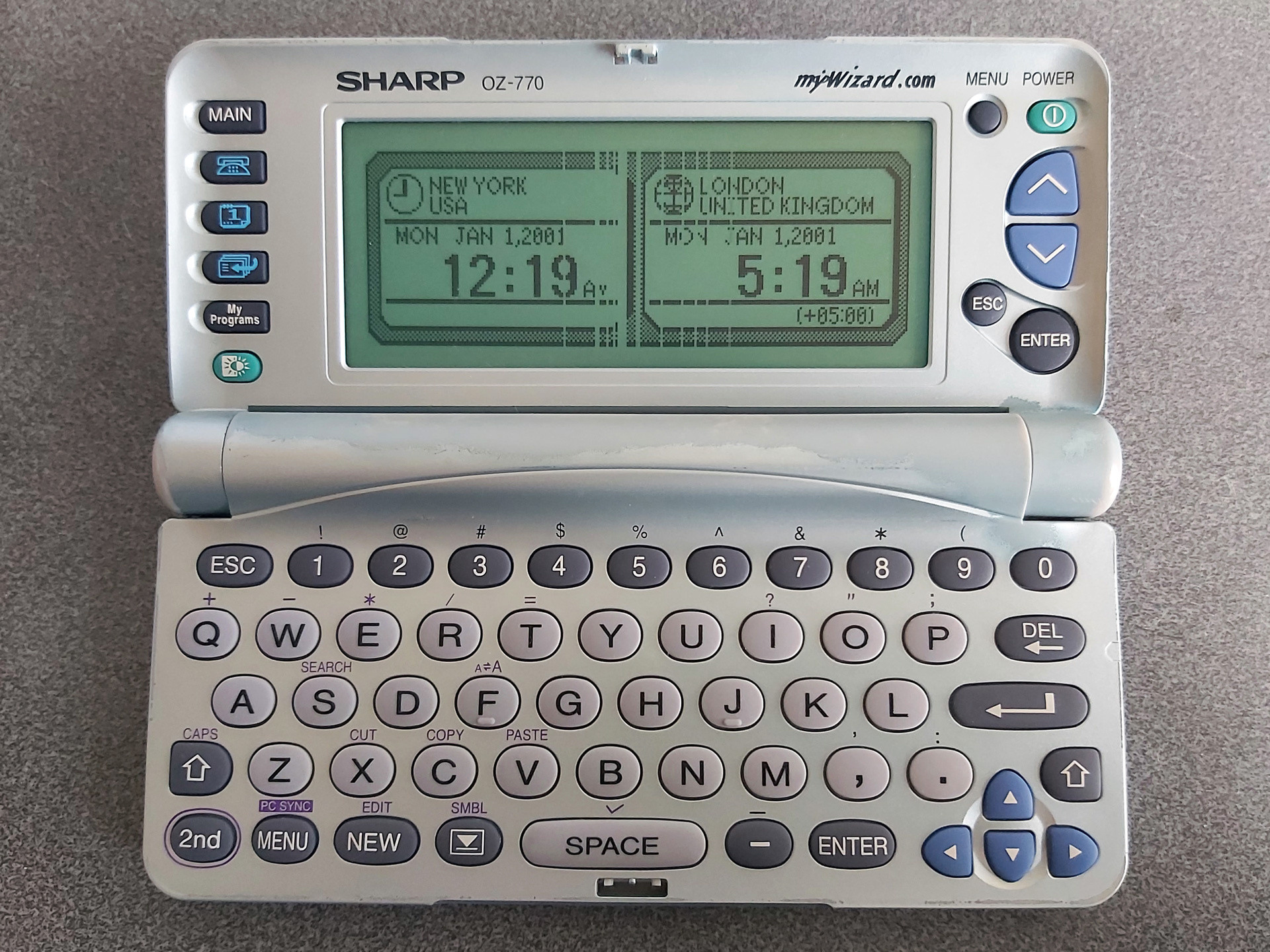
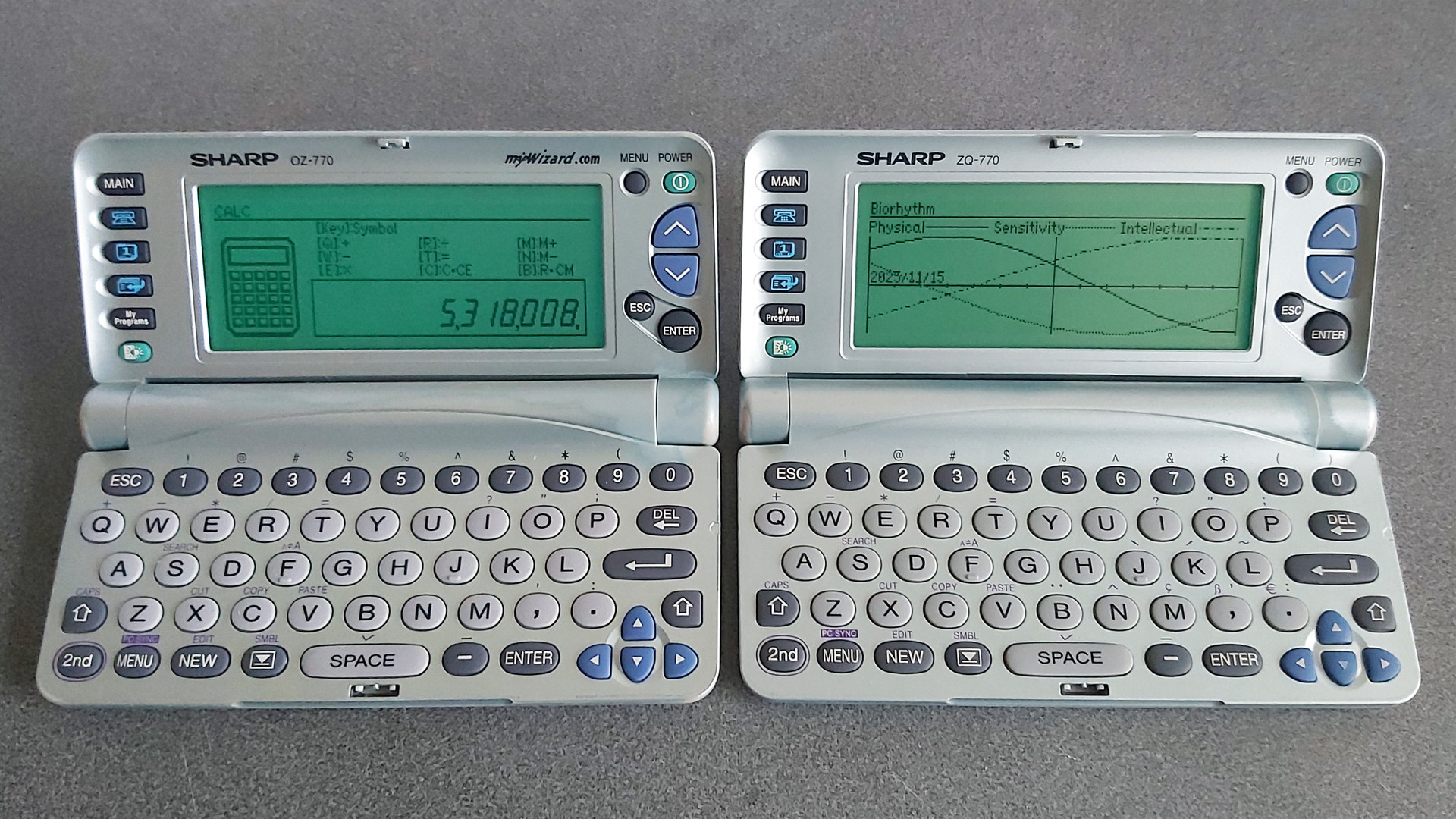
The Sharp ZQ-700 Electronic Organizer, also sold as the Sharp OZ-700 Wizard, was a pretty interesting device. Its large 239×80 pixel resolution back-lit LCD and QWERTY keyboard made it a comfortable device to use, though the built-in programs are somewhat simplified from Sharp's more sophisticated earlier offerings; there's also no card slot for software expansion and the connectivity is much more limited. Gone are the options to connect a serial modem, send a fax, print to a thermal printer or back up data to cassette tape, but perhaps this was all a sign of the times. The US version of the organiser proudly sports the mywizard.com domain name, and the features I mentioned were all pretty old hat in an era when the Internet was being rapidly embraced. Whilst the organiser could not directly connect to the Internet, the accompanying website allowed users to share and download data files for the organiser and synchronise them with a PC using the supplied data cable.
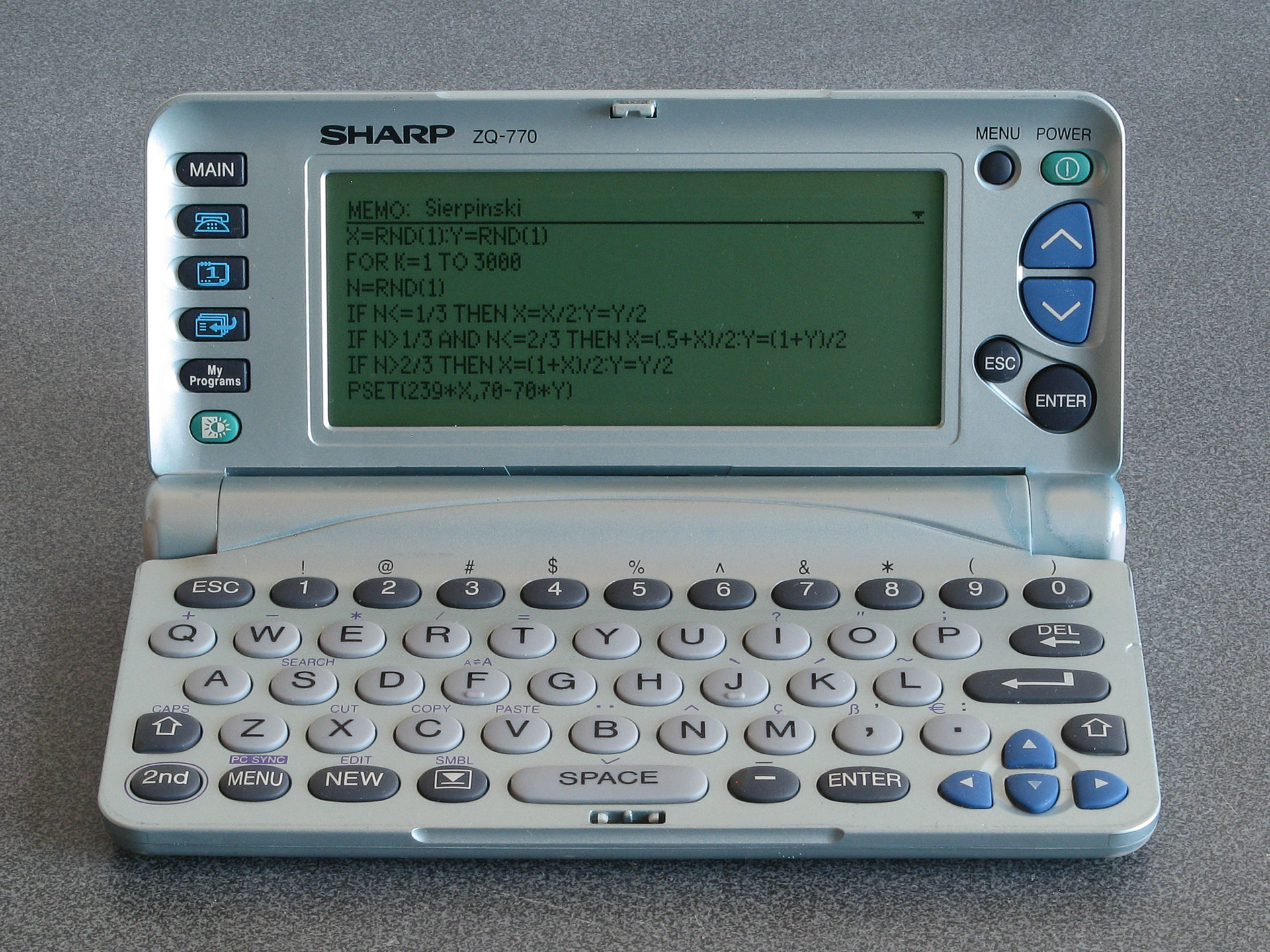
A programmable organiser: Sierpinski triangle code typed into a memo
Where this becomes particularly interesting the organiser's My Programs button. Previous Sharp organisers could be turned into pocket computers via the addition of a Scientific Computer card which included a powerful BASIC interpreter. The ZQ-700 has a BASIC interpreter built-in, and up to ten BASIC programs can be stored on the organiser and accessed via the My Programs button. Unfortunately, these BASIC programs cannot be edited directly on the organiser itself and there is no interactive BASIC prompt, but Sharp supplied a free SDK which let you edit BASIC programs and convert them into the tokenised form that could be transferred to the organiser. Being able to write your own programs to run on your organiser is an extremely powerful feature.
Even better, the BASIC interpreter does provide PEEK, POKE and CALL keywords even though these are not directly accessible when using Sharp's official SDK. By creating a BASIC program with a stub CALL at the start and appending machine code to the end of it it's possible to run native code on the organiser. The organiser is powered by a Z80 CPU, and so a user-developed alternative SDK (including a C compiler) was released, allowing people to write their own native code for the organiser.
Unfortunately, most of the sites relating to the ZQ-700 and its community are long-gone. The official mywizard.com has been offline since at least 2009, though interestingly Sharp do still host some downloads relating to the organiser on their global website. The mywizard.com site eventually required user registration to download files, so very little of the user-generated content has been preserved by the Internet Archive. However, some of the hobbyist sites about the organiser have been preserved there, so it is possible to scrape together a bit of a software collection that way.
LCD repair
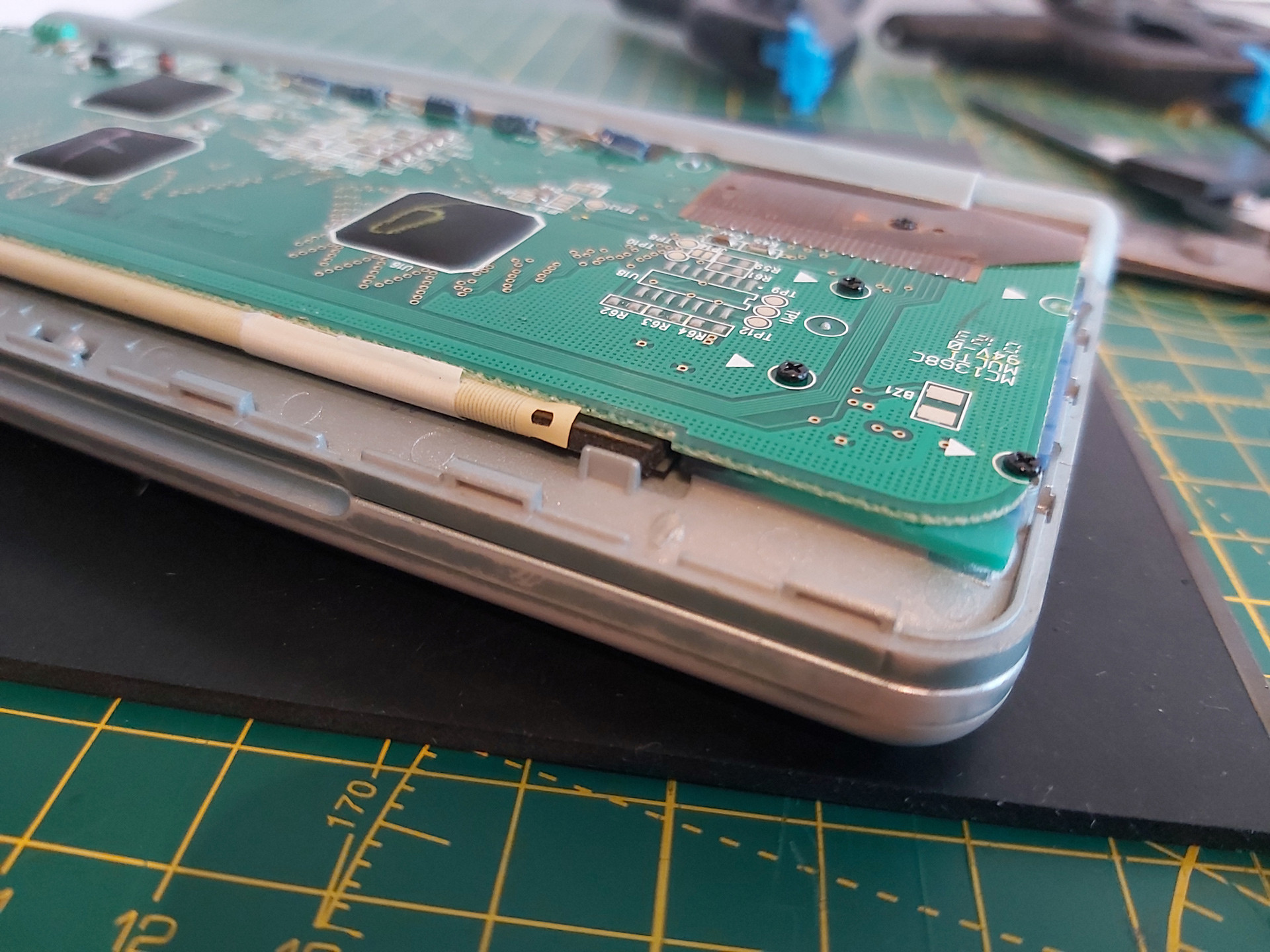
Aside from the link rot there are some more pressing age-related issues with the ZQ-700 relating to its LCD. Or, as the case may be, non-pressing issues as the flat flex cable that provides an electrical connection between the main PCB and the LCD's rows and columns gradually comes unstuck.
The photo above shows the typical state of the organiser's LCD after all these years. The discoloured paintwork around the hinges is somewhat less typical; I bought two organisers recently for cheap due to their non-working condition, and both showed signs of severe alkaline battery leakage. The two organisers were sold as a pair, and both were showed the same owner's name and address when powered on. I always find it interesting if an electronic organiser has any old user data on it, as it gives you an impression of how much the owner appreciated the device; in this particular case these organisers were very heavily used, with around 5,000 records stored on each. This gave me all the more inclination to want to repair them. As well as thousands of contact details and diary entries there were also numerous BASIC programs in the My Programs section, all related to cars and financing, so I thought it would be worth trying to find a way of backing up said programs before erasing all of the personal data from memory.
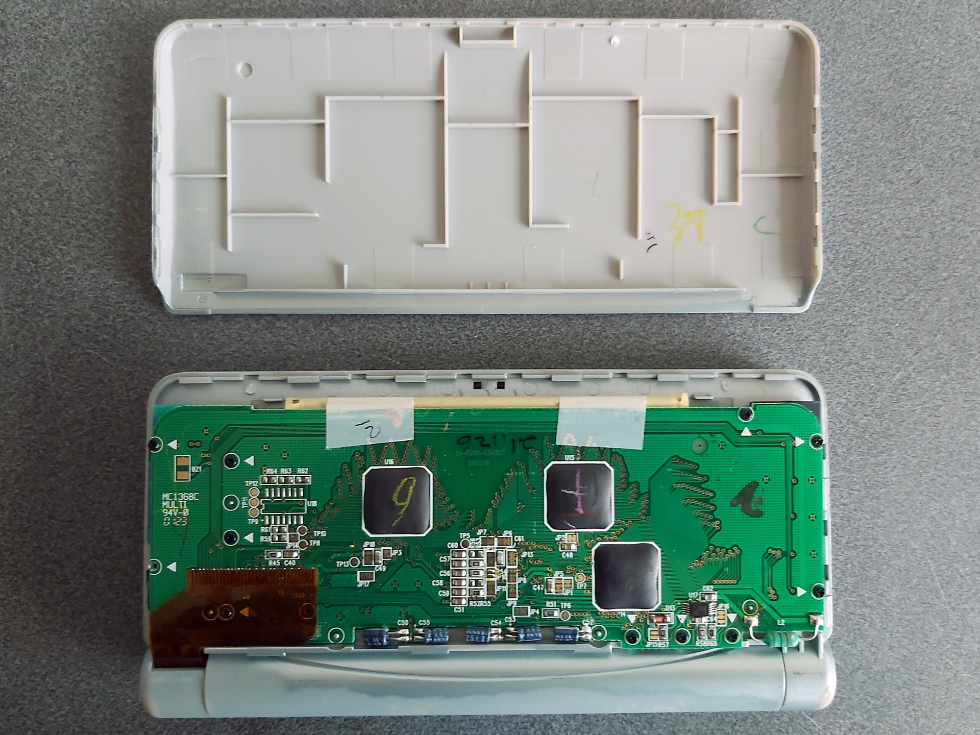
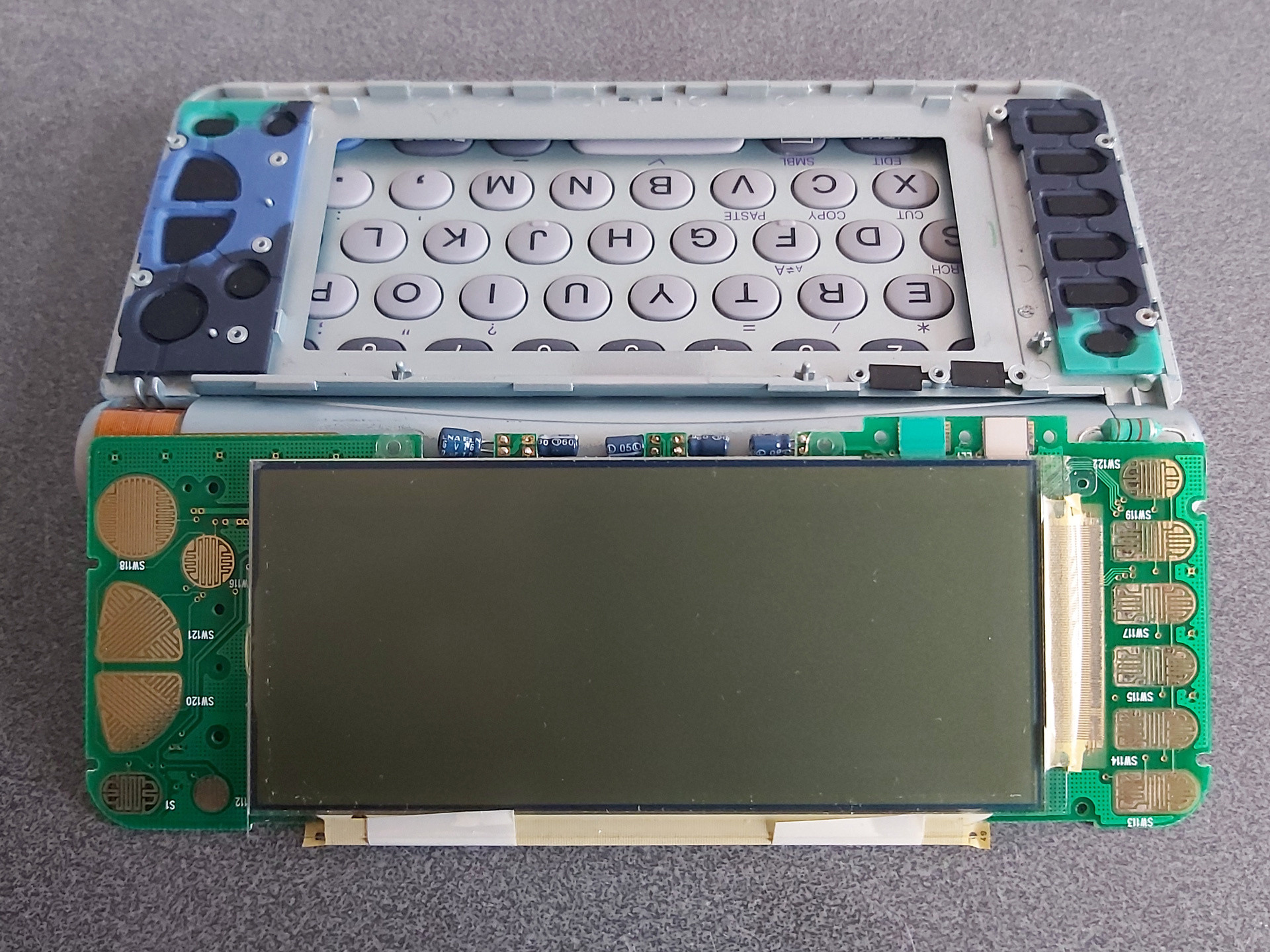
Getting access to the LCD is reasonably easy; the rear cover simply clips on. I find it easies to start popping it off near the hinge side, unclipping both sides and working up towards the top edge furthest away from the hinge. Some screws hold the PCB in, with each screw hole marked with a white triangle. In my case one screw was missing from the factory! The LCD glass itself is secured to the front of the screen housing with double-sided tape; some gentle pressure on the screen from the inside will unstick it.
The flat flex cables that are stuck to the LCD glass use a heat-activated adhesive. One potential fix for the cables coming unstuck is to heat them with a soldering iron to reactivate the adhesive, though this is a somewhat risky procedure. In this case, however, that is not an option due to the use of two cables at right angles to each other, with the problematic column-driving cable being folded between the LCD and PCB with no easy way to access it with a soldering iron.
A mechanical fix can be an option, however. This involves finding some way to put pressure between the flex cable and the PCB and/or LCD to physically hold the cable against the contacts. Thin rubber sheeting can work well for this, and for the ZQ-700 series I've found cutting a piece that's 3mm wide and about 105mm long from a 2mm thick sheet does a good job.

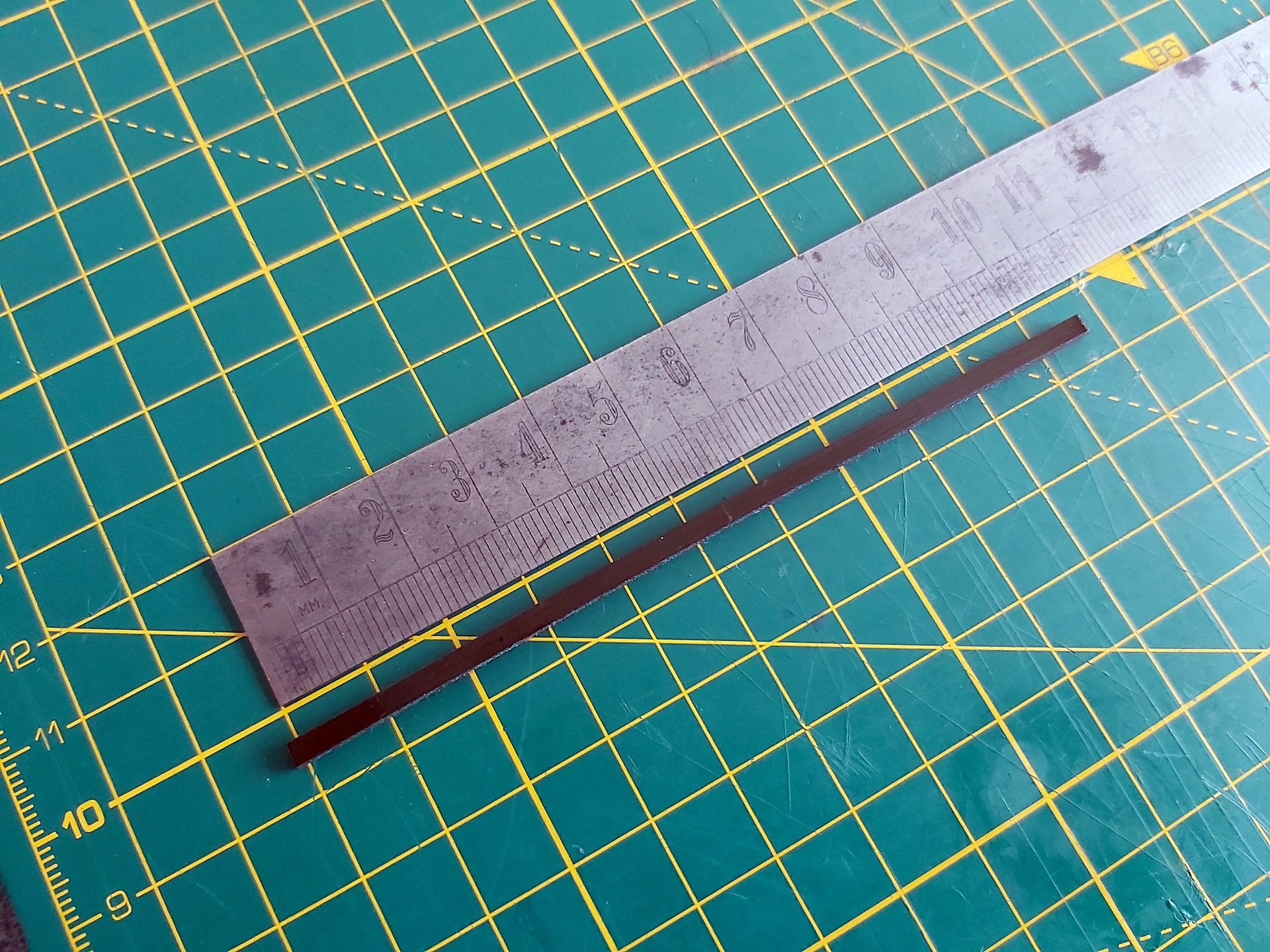
I also put two layers of Kapton tape on each side of the rubber strip before cutting it out. Aside from a little extra thickness, this gives the otherwise grippy rubber strip a smooth surface that will make it easier to slide into the fold of the flat flex cable between the LCD and its PCB.
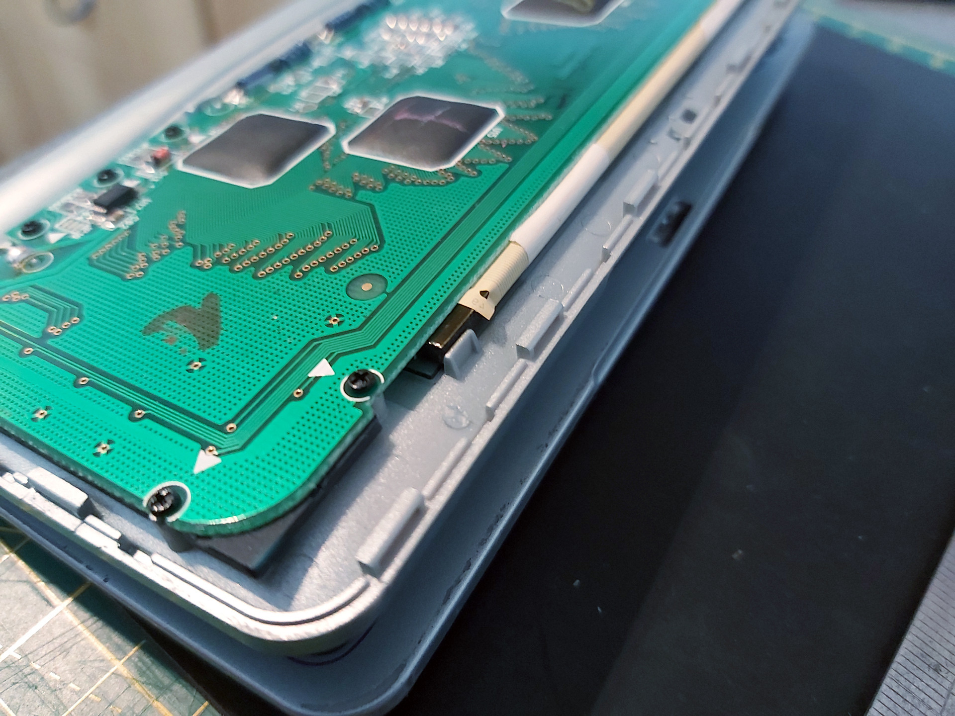
There are two pieces of white tape stuck to the back of the PCB and the flat flex cable which pull on the cable slightly and can make it harder to install the rubber strip. Rather than remove these entirely I very carefully peeled them off the PCB and then cut them rather than try to peel them off the fragile flat flex cable and cause further damage.
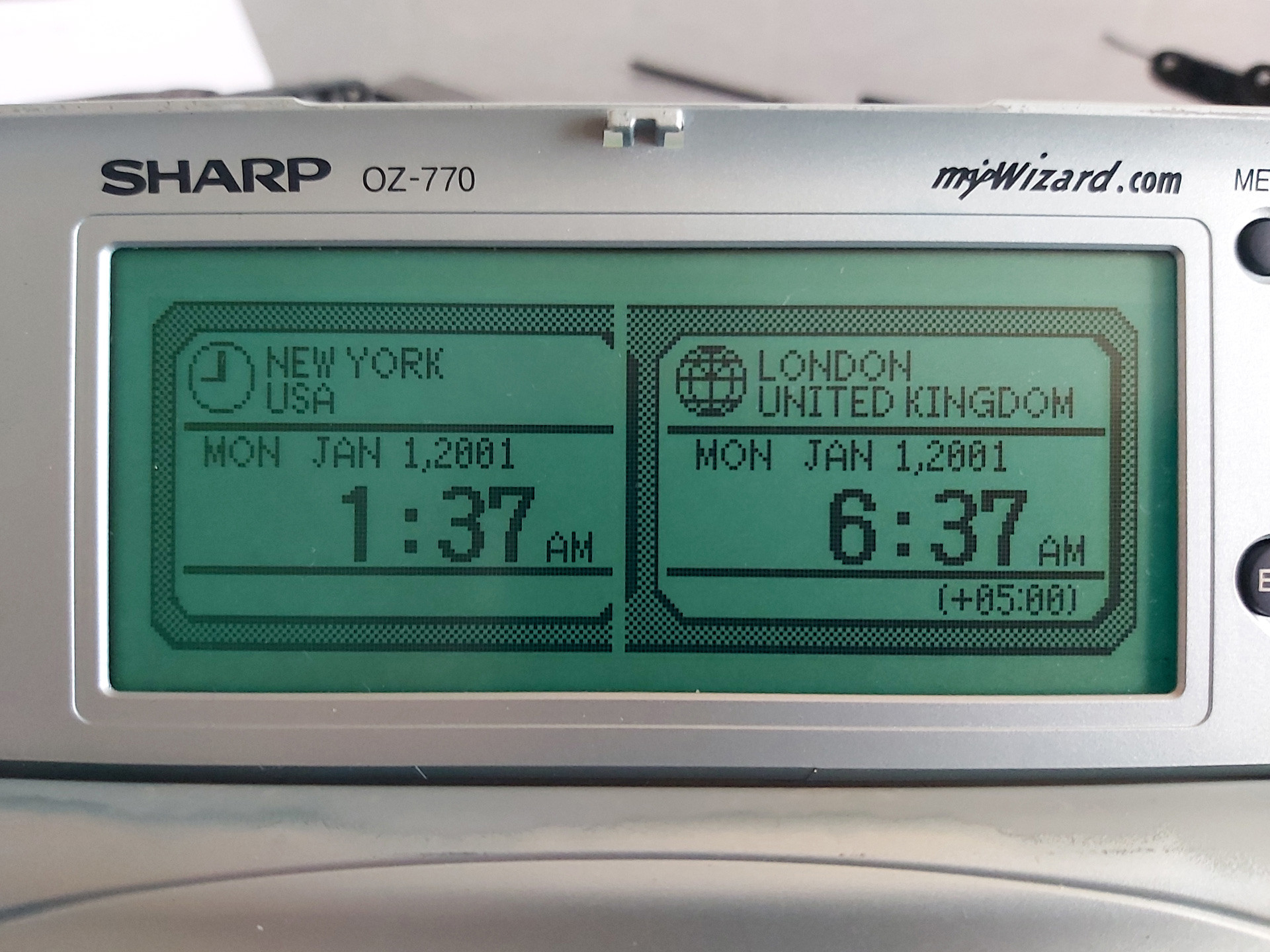
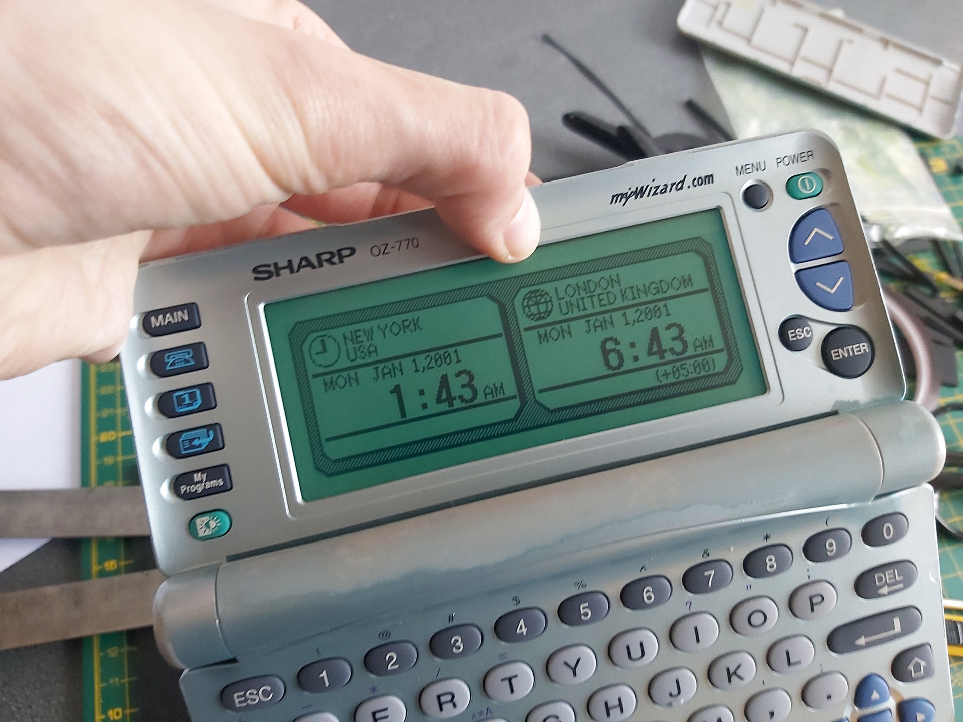
After installing the rubber strip and screwing the PCB back down, there was a notable improvement but not all of the columns came back. Putting some additional pressure on the back of the board in just the right place resulted in a complete picture. One possible way to apply this pressure is to put something inside the back cover so that when it's clipped back on it simulates what my thumb was doing in the previous set of photos:
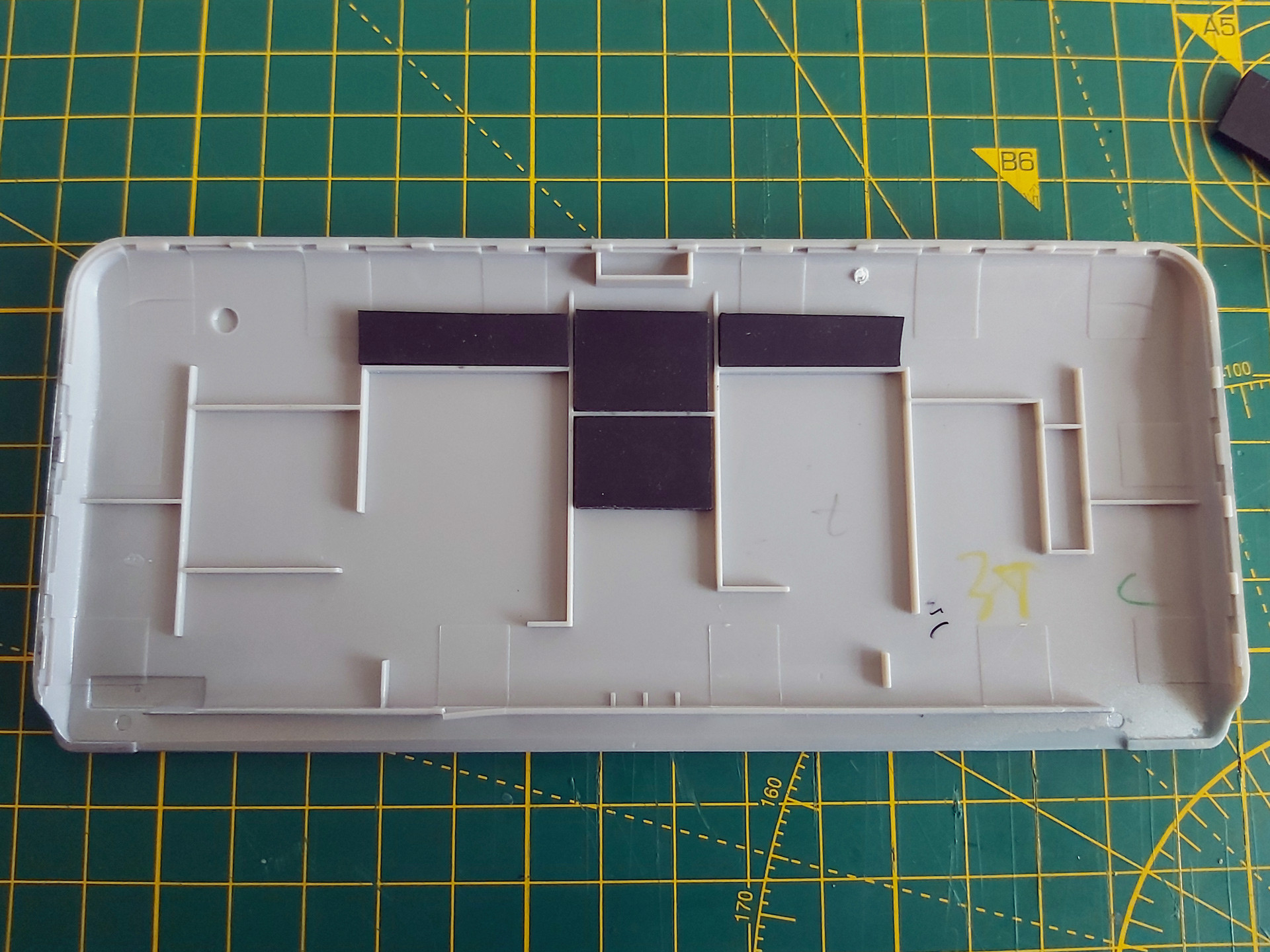
Unfortunately in this organiser's case there was still one missing column, and this was with so much rubber stuck inside the back cover that the whole screen was bowing outwards and could no longer be clipped shut. This clearly wasn't the answer, so the rubber pieces inside the back cover were peeled off. Some targeted application of the heat treatment seemed like the next best option.

There is no direct access to the flex cable, however there is nothing too delicate on the opposite side of the PCB which we do have access to – mostly just a thick copper track. A pair of spring clamps were placed on either side of the missing columns, applying firm pressure to the cable courtesy of the rubber strip inside its fold. The soldering iron was set to 350°C and held against the copper track for a few seconds. Everything was left to cool, then the results were checked – all columns were back!
I must stress this is a risky operation, as the flex cable is very delicate and heating it can ruin it. 350°C is far too hot for directly heating the cable and if the soldering iron slips and makes contact with the cable you'll probably melt a hole in it. When directly heating the cable I use an iron at around 240°C, but even then I only lightly swipe it across the cable in the direction of the contacts – no prolonged contact and no firm pressure.
Once I had the OZ-770 working I turned my attention to the ZQ-770, the other organiser from the pair. This one also has faulty columns on its display, however the fault is rather more intermittent – gently flexing the screen brings the missing columns back, and once the organiser has been on for a short while they generally remain visible until the organiser is switched off for a while. It'll probably need repairing in the future, but for now it's working well enough that I don't want to risk accidentally making it worse.
Backing up My Programs from ZQ-700 series organisers
One of the two organisers I'd bought had a number of BASIC programs loaded into the My Programs area. Unlike the personal data, which I had wiped, I thought it would be interesting to preserve these BASIC programs. Connecting the organiser to a PC is easy enough via an RS-232 serial cable; though I don't have an original one, I was able to make my own from a 3.5mm TRRS connector and a DE-9 plug following the wiring diagram on IMSL Software's copy of a page from the OZdev website. IMSL Software also develop the XLink/Win software which can be used to synchronise data between a Windows PC and an organiser, though this won't let you back up the data from My Programs.
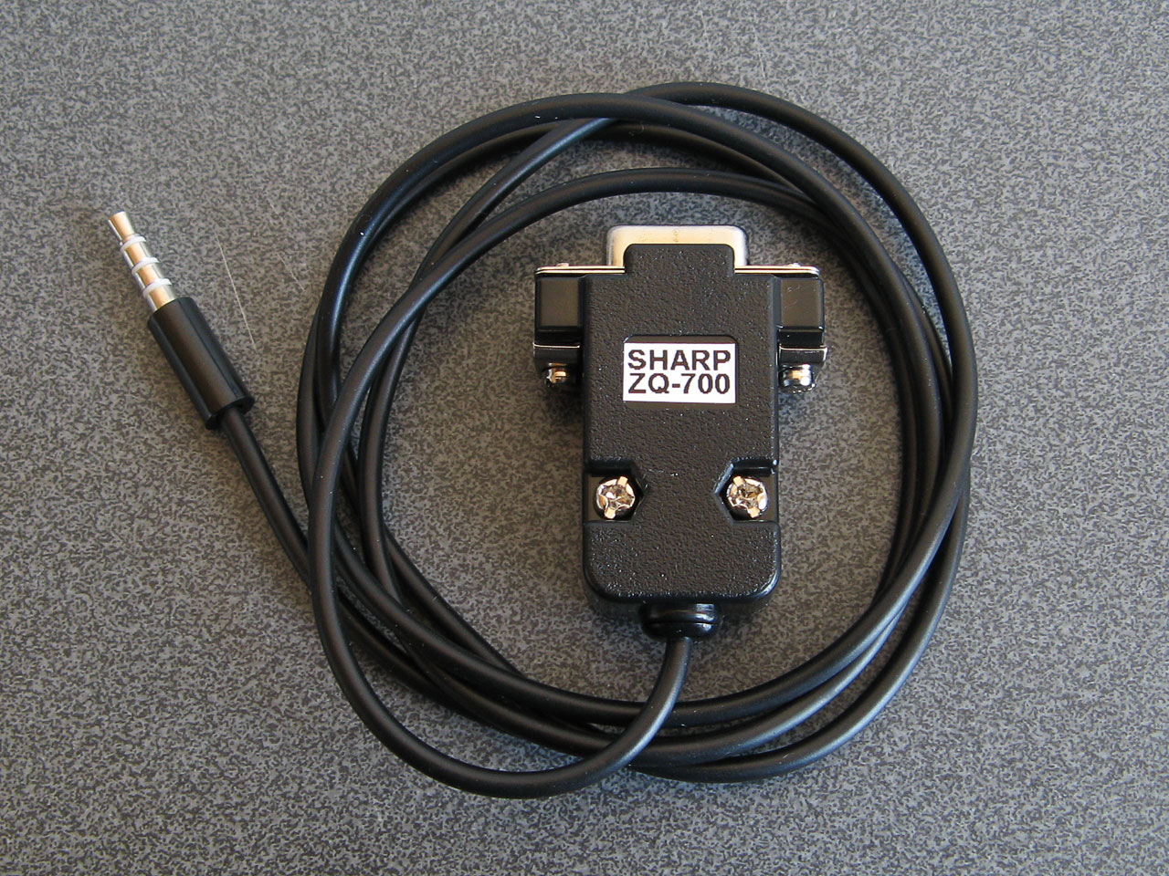
A home-made serial cable for the ZQ-770
Sharp supplied a copy of Day-Timer Organizer for similar purposes and though this won't help back up My Programs either there is a handy backup utility on the CD that can dump the entire contents of the organiser to a file. Someone has uploaded a copy of this OZ-700 Software CD-ROM to the Internet Archive, and though it can't seem to restore backups on modern versions of Windows it happily created backup images from my organisers.
I did take a look at the created backup files and though they looked like nonsense at first I think this is because all of the bit values are inverted. After flipping the bits back I could find various program fragments, though they not contiguous so I suspect there's a file system or similar data structure embedded in the backups that make pulling out the data a little more difficult.
Fortunately this is a solved problem: SbkExplorer can open the backup .sbk file and export the programs as individual .wzd files, ready for reinstallation on other organisers.

Extracting files from the My Programs portion of a backup using SbkExplorer.
When these BASIC programs were originally developed using Sharp's SDK they were stored as a .bas containing the source code as a plain text file and a .prj project file that contained some information about the program such as its full name and a text description. The program would be "compiled" into a .obj file (effectively a tokenised BASIC program with the comments stripped out) and then published as a .wzd file which is an XML-like file containing the description from the project file and the compiled object file as raw binary data. Sharp's downloader tool could then open the .wzd file, show the project description on the screen, and allow the user to transfer the compiled BASIC program to their organiser's My Programs menu.
The .wzd file recovered by SbkExplorer won't be a perfect match for the one used to install the program originally, as it will be missing any descriptive text. However, it's good enough to back up an installable version of the original program file. If you wanted to edit the source code for the program, then the Sharp Wizard Decompiler can be used to extract a .bas file from the .wzd. Again, this won't be a perfect match for the source material as any comments would have been stripped out by the Sharp SDK, but it's definitely a good starting point to recovering old programs.
Links to OZ-770 resources
Unfortunately, a lot of the old sites that used to host information about this series of Sharp Organisers are long gone. Fortunately, the Internet Archive's Wayback Machine has copies of a lot of them, and I've linked to those archived copies where the original sites are no longer online.
General tools
- Sharp's Software Downloads ZQ-700 series page still hosts the Downloader, Data Creation and SDK tools for the organiser as well as some sample installable .wzd files.
- IMSL Software show how to make a serial cable for the organiser and sell XLink/Win linking software that is compatible with the organiser.
- Day-Time Organizer: Sharp Edition was originally bundled with the organiser on CD-ROM and can be used to back up and restore data from the organiser.
- SbkExplorer can be used to extract data from a .sbk backup (created using the Backup Utility on the previous CD-ROM).
File archives and information about the organiser
- Wizworld.
- The OZ-750 Paradise.
- Marshall's Amazing Wizard Organizer.
- Nadisha Ranmuthu's Wizard.
- Grigori Fursin's Homepage (FSFM).
- Software for the PC and for Sharp Wizard OZ/ZQ 7xx Organizers mainly by Alex Pruss.
Software development
- OZdev Wizard Development: 2001, 2002. Lots of good information but the archives have some broken links, hence two captures from the two different domains are provided.
- Official Sharp SDK to develop programs using BASIC.
- Zifnab, an alternative SDK for developing BASIC programs (includes additional keywords like PEEK, POKE and CALL).
- Bacon, an organiser add-on that lets you execute BASIC programs created directly on the organiser as memos.
- Sharp Wizard Decompiler to decompile .wzd files into BASIC source files.
- C SDK with a lot of sample code.
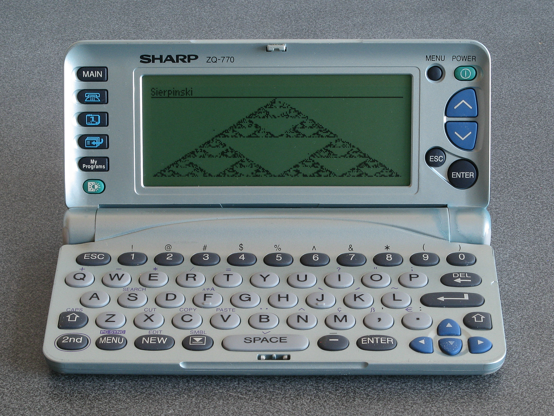
The result of running the Sierpinski triangle code from the earlier memo using Bacon
If you pick up one of these old organisers you can probably have quite a lot of fun with it as a pocket computer containing a Z80 CPU, a large LCD and QWERTY keyboard. It's just a shame about the poor durability of the screen.
Printing graphics from a Cambridge Z88 on a Serial 8056 via the BASIC patch
Saturday, 29th November 2025

I've got a number of older computers that can print, but no printer for them. Quite often these computers require a serial printer, and so when a Serial 8056 printer popped up on eBay for around a tenner I picked it up. This is a thermal printer that takes fax paper rolls, so it seemed like a safe bet as far as consumables go (no need to source awkward cartridges, ink ribbons or spark paper) and the listing claimed it was intended for the Sinclair QL.
When it turned up I was a bit surprised by the plug on the end of the cable – two rows of eight pins, similar to a 16-way IDC connector, and not the phone jack style connector the QL needed. Fortunately the data (RD) and CTS pins were marked on the circuit board inside the printer and I was able to trace them out to the plug and bodge together a cable to plug it into my PC. Between articles from Format magazine, QL World and Popular Computing Weekly about the printer I was able to find the baud rate (1200), a few control codes for formatting and how to output graphics. Still puzzled by the non-QL plug I asked Reddit and that's when it was pointed out that the Serial 8056 is really a rebadged IBM PC Compact Printer originally sold for use with the PCjr. If my particular printer had been intended for use with the Sinclair QL then it would have included the appropriate adaptor in the box.
Knowing this, however, it made it easier to find information about the printer, including a reference manual, confirming the information I'd gleaned from the magazine articles about the Serial 8056.
One of the computers I had planned to use the printer with was my Cambridge Z88. Setting this up as a text printer was easy enough, but I'd been intrigued by a feature of the Z88 BASIC Patch, as described by the notes:
Unfortunately, the Z88 BASIC Patch source code release appears to be missing the printer code. I turned to Ghidra to disassemble the patch, and found the pertinent routines.
As the routines send a dump of the graphics window (the "map" in Z88 parlance) to the printer, I named the main routine DUMPMAP. One of the first things it does is to reset the printer via a routine I named DUMPRESET. This sends ESC @ to reset the printer (the Epson ESC/P reference may be useful here), then sends two line feeds. It falls through to the routine that is used to send bytes to the printer, which I've named DUMPWRCH:
                    *************************************************************************
                    * Resets the printer to its initial settings and outputs two line feeds *
                    *************************************************************************
                    DUMPRESET
ram:2bb5 3e 1b             LD           A,0x1b       ; ESC
ram:2bb7 cd c6 2b          CALL         DUMPWRCH
ram:2bba 3e 40             LD           A,'@'        ; ESC @ = Initialize printer
ram:2bbc cd c6 2b          CALL         DUMPWRCH
ram:2bbf 3e 0a             LD           A,'\n'       ; Line feed
ram:2bc1 cd c6 2b          CALL         DUMPWRCH
ram:2bc4 3e 0a             LD           A,'\n'       ; Line feed
                    *************************************************************************
                    * Write a byte to the serial port with a 1 second timeout               *
                    *************************************************************************
                    DUMPWRCH
ram:2bc6 f5                PUSH         AF
ram:2bc7 01 64 00          LD           BC,100       ; 100cs timeout
ram:2bca e7                RST          SYS
ram:2bcb 42                db           OS_Pbt       ; Write the byte to the serial port
ram:2bcc f1                POP          AF
ram:2bcd c9                RET
The DUMPRESET routine is also used at the very end of printing to reset the printer and ensure two line feeds appear after the graphics dump. Graphics data are sent as 8 pixel high rows with condensed line spacing, one byte per column. The relevant code that starts this process of each row is as follows: first the line spacing is set to 1/9-inch using ESC 3, a line feed is sent, there's a one second delay to give the mechanism time to advance and then graphics mode is entered with ESC L and a request to send 768 bytes:
ram:2b33 3e 1b             LD           A,0x1b       ; ESC
ram:2b35 cd c6 2b          CALL         DUMPWRCH
ram:2b38 3e 33             LD           A,'3'        ; ESC 3 = Set n/216-inch line spacing
ram:2b3a cd c6 2b          CALL         DUMPWRCH
ram:2b3d 3e 18             LD           A,24         ; 24/216 = 1/9-inch line spacing
ram:2b3f cd c6 2b          CALL         DUMPWRCH
ram:2b42 3e 0a             LD           A,'\n'       ; Line feed
ram:2b44 cd c6 2b          CALL         DUMPWRCH

ram:2b47 01 64 00          LD           BC,100       ; 100cs
ram:2b4a e7                RST          SYS
ram:2b4b 2d                db           OS_Tin       ; Wait for a key for 100cs

ram:2b4c 3e 1b             LD           A,0x1b       ; ESC
ram:2b4e cd c6 2b          CALL         DUMPWRCH
ram:2b51 3e 4c             LD           A,'L'        ; ESC L = Select 120-dpi graphics
ram:2b53 cd c6 2b          CALL         DUMPWRCH
ram:2b56 3e 00             LD           A,0          ; nL = 0
ram:2b58 cd c6 2b          CALL         DUMPWRCH
ram:2b5b 3e 03             LD           A,3          ; nH = 3: 768 bytes
ram:2b5d cd c6 2b          CALL         DUMPWRCH
The graphics window (map) is only 256 pixels wide, though, so why 768 bytes? Well, the printing code actually scales the image up before printing: it doubles the height and triples the width of each pixel. When outputting a row of graphics data, each column byte is sent three times:
ram:2b7c cd c6 2b          CALL         DUMPWRCH
ram:2b7f cd c6 2b          CALL         DUMPWRCH
ram:2b82 cd c6 2b          CALL         DUMPWRCH
This is all of the Epson-specific printer code, and fortunately it maps pretty well to the Serial 8056:
| Action | Epson ESC/P | Serial 8056 |
|---|---|---|
| Initialise printer | ESC @ | CAN |
| Set 1/9-inch line spacing | ESC 3 n=24 | ESC 1 |
| Output bitmapped graphics | ESC L n=768 [768 bytes] | ESC K n=512 [512 bytes] |
Ideally, the Epson codes could simply be patched with the equivalent Serial 8056 codes but there is one slight spanner in the works: the Serial 8056 needs a carriage return to be sent after each line and the code doesn't do that and there's no easy way to insert it at the end of the relevant printing routines.
However, it is possible to insert a carriage return at the start of each line, which means that each line will start by ending the preceding one. This does still leave the final line, but fortunately the code calls DUMPRESET after printing the last line and so an additional carriage return can be inserted at the start of that routine to terminate that line.
It's not quite as elegant a patch, as the order of some code needs to be adjusted rather than just patching the Epson codes with the equivalent Serial 8056 codes, but it's not too bad overall. The full list of code changes are as follows:
                    DUMPRESET
ram:2bb5 3e 1b             LD           A,0x1b       ; Change to CR: ?&2BB6=13
ram:2bb7 cd c6 2b          CALL         DUMPWRCH
ram:2bba 3e 40             LD           A,'@'        ; Change to ESC: ?&2BBB=27
ram:2bbc cd c6 2b          CALL         DUMPWRCH
ram:2bbf 3e 0a             LD           A,'\n'       ; Change to '2': ?&2BC0=50
ram:2bc1 cd c6 2b          CALL         DUMPWRCH
ram:2bc4 3e 0a             LD           A,'\n'
The need to insert an extra carriage return at the start of the reset routine means we can only output a single line feed after resetting the printer instead of the original two. You may also be wondering why the printer is "reset" with ESC 2 instead of CAN, as that would save a byte – in my case it doesn't appear that resetting the printer that way resets the line spacing, which means that the printer gets left in the 1/9-inch line spacing mode. ESC 2 explicitly restores the 1/6-inch (default) line spacing mode.
The code that runs at the start of each line of output is a bit more awkward to change, unfortunately. The original code currently works like this:
- Send ESC
- Send '3'
- Send 24
- Send LF
- Wait 100cs
However, our new code needs to do this instead:
- Send CR
- Send LF
- Wait 200cs*
- Send ESC
- Send '1'*
Three of the five operations line up, however two of them (sending a byte of data and introducing a delay, marked with an asterisk) are swapped, which means that two code blocks in the code need to be swapped. Very fortunately, the code for each operation is the same size (five bytes) which at least means that the code between them can be left in the same place.
ram:2b33 3e 1b             LD           A,0x1b      ; Change to CR: ?&2B34=13
ram:2b35 cd c6 2b          CALL         DUMPWRCH
ram:2b38 3e 33             LD           A,'3'       ; Change to LF: ?&2B39=10
ram:2b3a cd c6 2b          CALL         DUMPWRCH

ram:2b3d 3e 18             LD           A,24        ; Change to 200cs delay: ?&2B3D=1 ?&2B3E=200
ram:2b3f cd c6 2b          CALL         DUMPWRCH    ; ?&2B3F=0 ?&2B40=231 ?&2B41=45

ram:2b42 3e 0a             LD           A,'\n'      ; Change to ESC: ?&2B43=27
ram:2b44 cd c6 2b          CALL         DUMPWRCH

ram:2b47 01 64 00          LD           BC,100      ; Change to DUMPWRCH '1':
ram:2b4a e7                RST          SYS         ; ?&2B47=62 ?&2B48=49
ram:2b4b 2d                db           OS_Tin      ; ?&2B49=205 ?&2B4A=198 ?&2B4B=43
The time delay is handled by calling the OS input routine with the timeout delay specified in register BC. The original code used 100cs, i.e. 1 second. When I was testing the code I ran into some issues: the first few lines printed fine, but the last couple of lines ended up failing to print, with the preceding lines showing some junk characters at the end of each line. Extending the delay to 200cs fixed the issue, but I was not sure why the first few lines printed fine and the problem only manifested itself at the end of the print until I looked at the movement of the print head more carefully.
The test image I was using was a row of Sierpinski triangles, and so the rightmost pixels were mostly white in the early rows but increasingly black as the triangles widened towards the bottom of the image. It turns out that if the end of the line is white the print head returns back home early, and so the one second delay was enough when the print head was skipping the end of the line but not quite enough when it had to travel the full distance back to the left edge. Extending the delay to two seconds provides more than enough time for the carriage to return.
When it comes to sending the actual bitmap data to the printer only a simple modification is required:
ram:2b4c 3e 1b             LD           A,0x1b
ram:2b4e cd c6 2b          CALL         DUMPWRCH
ram:2b51 3e 4c             LD           A,'L'        ; Change to 'K': ?&2B52=75
ram:2b53 cd c6 2b          CALL         DUMPWRCH
ram:2b56 3e 00             LD           A,0
ram:2b58 cd c6 2b          CALL         DUMPWRCH
ram:2b5b 3e 03             LD           A,3          ; Change to 2: ?&2B5C=2
ram:2b5d cd c6 2b          CALL         DUMPWRCH
Instead of ESC L with an argument of 768 bytes (&0300) we need to send ESC K with an argument of 512 bytes (&0200). The code will still try to send 768 bytes by repeating each column of the 256-pixel wide image three times, so instead we need to only send each column twice:
ram:2b7c cd c6 2b          CALL         DUMPWRCH
ram:2b7f cd c6 2b          CALL         DUMPWRCH
ram:2b82 cd c6 2b          CALL         DUMPWRCH     ; Change to CALL <dummy>: ?&2B83=&B4
The final CALL could be replaced by three NOP bytes but rather than do that the address of the target is patched to &2BB4. This address contains a RET instruction as it's the final instruction of a nearby routine so effectively turns the CALL into a NOP.
This completes the patch itself; the only thing needed to do is to wrap it up into a neat installer. Here is the result of that, in BBC BASIC:
   10 REM Serial 8056 Patch for Z88 BASIC
   20 C%=0:FORA%=&2B03TO&2BF6:C%=C%+?A%:NEXT
   30 IFC%=&5BF1PRINT"Patch already applied.":END
   40 IFC%<>&5BB9PRINT"Please load Z88PATCH.BBC first.":END
   50 READA%,V%:REPEATA%?&2B00=V%:READA%,V%:UNTILA%<0
   60 PRINT"Patch applied: use CALL 11011 to print.":END
   70 DATA&B6,13,&BB,27,&C0,50
   80 DATA&34,13,&39,10,&3D,1,&3E,200,&3F,0,&40,231,&41,45
   90 DATA&43,27,&47,62,&48,49,&49,205,&4A,198,&4B,43
  100 DATA&52,75,&5C,2,&83,180,-1,0
Line 20 first calculates a checksum of the area targeted by the patch, which is then checked in lines 30 and 40 for two known states: Serial 8056 patch already applied and Z88PATCH loaded but Serial 8056 patch not applied. Line 50 reads the patch data itself (stored in lines 70 to 100) which is made up of addresses and patch value pairs; as all bytes to patch appear in the &2Bxx address range only the least significant byte of the address is stored.
In summary, if you have a Serial 8056 and a Cambridge Z88 and wish to print graphics from BBC BASIC you may find the Serial 8056 for Z88 patch useful. You will also need the Z88 BASIC Patch as a starting point.
40-column text modes on Sharp organisers with the 16-column IQ-707 BASIC card
Wednesday, 2nd July 2025
Recent posts on here have taken a bit of a detour into Sharp Pocket Computer territory. When hunting down parts or accessories for them on eBay I'll occasionally be recommended other Sharp devices, such as their calculators or organisers, if an exact match for the thing I'm actually hunting for can't be found. Calculators are indeed a useful tool, so I appreciate those recommendations, but mid-1980s electronic organisers are not usually the sort of thing I'd be too interested in.
However, some of Sharp's organisers are definitely worth a look, and these are often considerably cheaper to pick up second-hand than pocket computers or calculators. I suspect this is partially due to difficulty in testing them and perhaps a bit of user error – they often require a large number of CR2032 cells to be installed, usually after removing a screwed-on back cover, and have a series of interlock switches that all need to be set just right before the device will even try to switch on. As a result, I've acquired quite a large collection of them for very little money, mostly sold as faulty or untested but all working just fine.

These particular organisers have a card slot on them, which can be used to expand the device's capabilities via a credit card-sized "IC card". The most common sort that you'll find is a RAM expansion card, which allows you to store more data (notes, calendar appointments, address book entries and the like) in a separate area to the device's built-in memory. More interesting, however, are the application IC cards. Dictionaries, thesauri, spreadsheets and even games were made available.

To me the most appealing is the Scientific Computer Card. The organisers do have a simple calculator built in, but the Scientific Computer Card adds more advanced calculator features such as trigonometric functions, logarithms and a statistics package. This is all handled via a very capable BASIC interpreter built into the card, and you can write your own programs on the organiser. The organisers also have a 4-pin "option" port that can be connected to a printer and cassette interface, and a 15-pin "PC link" serial port, so when you slot the card into your organiser you are in effect turning it into a pocket computer (though with all the accessories attached, you might need pretty large pockets!)

My only real criticism of this arrangement when compared to Sharp's dedicated pocket computers is the IQ-7000's keyboard. It's not too difficult to get used to the non-QWERTY alphabetic characters, but for BASIC programs you often need certain symbols (such as the speech mark, comma, semicolon, colon, less/greater than or ampersand) which are not present on the organiser's keyboard – they're only available via a pop-up menu that appears when you press the SMBL key. This menu only shows 10 options at a time and you need to hunt up and down through it to find the symbol you need; not an ideal experience!
Fortunately, Sharp released later organiser models (such as the IQ-8000) with QWERTY keyboards. Not only are these more comfortable to type on, but most of the symbols are now accessible via a shift key and these organisers retained backwards compatibility with the IC cards from the earlier IQ-7000 organisers.

The screen is also quite a bit larger and clearer, albeit now with non-square pixels which can make applications look a little skinny. Unfortunately, old applications developed with the 96×64 pixel display on the IQ-7000 in mind won't know how to take advantage of the 240×64 pixel display of the IQ-8000 and so are rendered on the left hand side of the display with a separator line. That seems like an awful lot of wasted space!

Application cards that took full advantage of the larger screens (up to 40 columns of text) were sometimes sold separately to the versions that were only designed for the smaller-screen devices (16 columns of text). For example, the above photo shows two cards of the same software – 3 Dimensional Spreadsheet for Electronic Organizer – with different card numbers (IQ-706A v IQ-8B01). The card on the right has 16/40 printed in the top right corner, showing it supports both 16-column and 40-column organisers. The card on the left doesn't, and will work in both, but will only display in the leftmost 16 columns.
As an aside, another difference is that the IQ-8B01 version has an extra "Graph" button on it. When the cards are inserted the front labels are visible through a transparent window. That window is touch-sensitive and allows cards to provide custom key shortcuts to certain functions. The graph function will work on a smaller-screen organiser though it is a little cramped; I'm not sure why it wasn't otherwise provided on the IQ-706A.
There was a 40-column version of the Scientific Computer Card available (card number IQ-8B03), however I have yet to find one come up for sale and so I've been making the most of my IQ-707. However, I did find something interesting when I used it on my IQ-8000: certain primitive drawing operations could access the whole screen, even if the rest of the application was constrained to a smaller window.


The photo on the left shows the results of drawing a line from (0, 0) to (239, 63) – the line ends up being drawn successfully outside of the 96×64 window at the left of the screen. The second photo uses the same coordinates but also appends the X (invert) and BF (box fill) options which should in theory invert the whole screen, but only ends up inverting the leftmost 96×64 pixels.
Certain other drawing operations (such as PSET and GPRINT) will also happily draw to the whole screen, but text cannot be positioned or drawn outside the 16×8 grid. At this point I wasn't sure if it was the BASIC interpreter or the organiser's OS that was to blame, but I wasn't really sure how to pick apart either of them.
One potential clue came in the form of the WIDTH statement. The IQ-7000 effectively has two screen modes, with differently-sized text characters: the default small font in a 16×8 grid and a larger font that reduces the number of displayed characters to 12×4. These modes can be switched by pressing the button marked 4↔8 Lines, or programatically via WIDTH 16,8 or WIDTH 12,4. The IQ-8000 expands these to 40×8 and 30×4, but trying WIDTH 40,8 or WIDTH 30,4 just displayed an error message. However, something, somewhere must know where the rightmost column number is to allow for proper text wrapping.
I mentioned that the BASIC interpreter is very capable, and it does have an undocumented PEEK function which allows you to read a byte from anywhere in the organiser's memory. I wrote a BASIC program that would scan through memory, switching screen modes with WIDTH and seeing if the value at the address in question changed. Once I'd done this I looked at the addresses that had values that changed in meaningful ways (e.g. between 16 and 12 or 8 and 4).
It looks like the current screen width (in characters) is held in BASIC's memory at &3F988 and the height at &3F989. POKEing a larger width into &3F988 does look like it might start working – if you type then the cursor goes off the right of the 96×64 window and can be seen blinking in the screen beyond, however no characters are printed in this area and certain operations (such as listing programs with long lines) misbehaves in strange ways. There must be more to the puzzle.
Unfortunately, without knowing more about the internal operation of the operating system or BASIC I wasn't sure where to look. However, having been able to draw lines on the full screen I contented myself with adapting a very clever program by @bazzargh that renders the Great Wave as a fractal for the device (the BASIC listing can be seen here: GREATWAV.BAS).

The next breakthrough was coming across this GitHub repository when looking for other technical reference documents. It has a scan of the "ESR-L Instruction Manual" which documents the Sharp ESR-L microprocessor. Some hand-written notes on the cover of the scan mention that it's "for the PC-E500, OZ-7000 series [and] IQ-7000 series", so should be useful for the IQ-7000 organiser. Looking up the PC-E500 led me to this repository from the same owner which has a PC-E500 reference. Even if the IQ-7000 is not the same as the PC-E500, the use of the same CPU in products from the same company made me think there may be other similarities to help understand how the IQ-7000 works. Using the PC-E500 as a search term also brought me to a page of resources on Andrew Woods' website and from there and digging around in the links (including a few trips to the Internet Archive's Wayback Machine) I was able to source a cross-assembler and disassembler.
I now felt I was in a good position to start pulling apart the BASIC interpreter and OS to figure out if it was possible to use the full screen on my IQ-8000. Of course, I'd need to have a ROM dump to inspect, and fortunately this was quite easy to pull off; after all, I already had a BASIC interpreter running on the device! A simple loop over the desired address ranges, PEEKing each byte then PRINT#ing it to the organiser's serial port with a program on my PC receiving the data and storing it in a file left me with some hefty binaries to dig into.
The size did indeed present a bit of a problem. I did have a disassembler, but not a particularly sophisticated one and feeding it the 128KB of BASIC interpreter ROM didn't provide particularly useful results. I'd normally use Ghidra for a job like this, but it doesn't know about the Sharp ESR-L CPU.
However, Ghidra is user-extensible and I did now have an instruction manual/reference for the CPU, so I did my best to learn how to describe the CPU to Ghidra. This was no small undertaking, as I didn't really know my way around the CPU yet myself. After a bit of work I put together this terrible first attempt. I do not recommend using it yourself, as I haven't fully checked that every instruction disassembles correctly and a very large number of instructions don't describe what they do (or if they do, they might do it incorrectly). The disassembly should be somewhat usable, but the decompilation is mostly useless at the moment.

I thought the title screen would be a good starting point to disassemble as I could clearly find where the strings for "BASIC Card" and the equals signs that form the border were in the binary, and from there find out where they were referenced and disassemble the instructions around those references until it made some sort of sense.
This is where the PC-E500 reference ended up being surprisingly useful, as it does share a fair amount in common with the IQ-7000. The way that both operating systems provide access to the hardware is via an IOCS routine at address &FFFE8, and the routine numbers and parameter assignments in the CPU's internal memory appear to be the same on both devices. One difference is certain locations in RAM are different (for example, the location of the text flags or the dot pattern used to draw lines) however these differences are fairly easy to identify.
If you look at the Ghidra screenshot above you'll see that the disassembly on the left looks vaguely sensible but the decompilation on the right is a right mess: for reasons I haven't yet figured out it appears to show stack operations during calls as assignments to variables on the stack (uStack000001 etc) and assignments to variables in RAM which are used as parameters to functions (e.g. BX and DX) are shown as both manual assignments and in the function call parameters.
Trusting the disassembly rather than the decompilation, I dug around in the code, trying to find something that was making use of the magic numbers relating to the screen dimensions: anything with 16, 8, 12 and 4 in close proximity would be a good candidate and I eventually found something promising:

The ESR-L is a little-endian CPU so the hex constants 0x810 and 0x40C in the following code correspond to (16, 8) and (12, 4) in memory.
050eb2 0a 10 08          MV           BA,0x810
050eb5 aa 46 fd 03       MV           [DAT_03fd46],BA
050eb9 0a 0c 04          MV           BA,0x40c
050ebc aa 48 fd 03       MV           [DAT_03fd48],BA
They're stored at &3FD46 and &3FD48 in memory, so directly adjacent to each other, and the surrounding code blocks operate on the cursor's X position and textflags, so it all seems highly relevant to what we're looking for. Those values in memory can be changed with POKE:
POKE &3FD46,40,8,30,4
The side-effect of this change is that you can now use WIDTH 40,8 and WIDTH 30,4 and the mode changes accordingly. However, when you type, text is still invisible once the cursor roams outside the leftmost 96×64 region of the screen. Clearly something else needs to change.
Further up in the code the values at &3FD46 and &3FD48 are copied from other values at &1FD9D and &01FD9F:
050e97 8a 9d fd 01       MV           BA,[DAT_01fd9d]
050e9b aa 46 fd 03       MV           [DAT_03fd46],BA
050e9f 8a 9f fd 01       MV           BA,[DAT_01fd9f]
050ea3 aa 48 fd 03       MV           [DAT_03fd48],BA
These source addresses are in the organiser's own memory rather than the memory built into the BASIC card, so it seems likely that these are the system values for width and height of the screen in the small and large fonts respectively and BASIC maintains its own copies of them which are the values we found before. We could POKE our new text resolutions into those memory locations too, which can be done with this program:
10 POKE &1FD9D,40,8,30,4
20 POKE &3FD46,40,8,30,4
30 WIDTH 40,8
40 CLS
After doing this, the whole screen becomes available to our BASIC program! All graphics operations work on the whole screen and text can be placed and displayed anywhere on it successfully:


I doubt this is the "correct" way to do it, and there is likely a proper IOCS call that updates the screen resolution. As a result there may be other system variables that are not properly updated by directly POKEing values into memory, but so far I haven't run into any significant problems. As I continue to work through the system ROM disassembly I may find the appropriate routines, however.
I did try to see if the full screen size was stored somewhere in the ROM image, as it would be useful to use this to know how to properly set the display mode according to the current organiser's capabilities. I did find the byte sequence (16, 8, 12, 4) in the IQ-7000 (&F083C) and IQ-7400 (&F478A) ROM dumps and the byte sequence (40, 8, 30, 4) in the IQ-8000 (&F1412), IQ-8200 (&F1418) and IQ-8300M (&F1423) ROM dumps. I couldn't find any code that was able to meaningfully access these sequences from a user application. There may be some way to properly identify the device you're running on but I'm not currently sure of a reliable way. One potential option is to use POINT(96,0) – this returns the status of a pixel on the display (0 for off, 1 for on), and crucially it returns -1 if the value is outside the screen bounds. On an IQ-7000 it returns -1, but on an IQ-8000 it returns 0 or 1. However, a later organiser model throws a spanner in the works…

This is the Sharp IQ-8920. Its screen is still 240 pixels wide, like the IQ-8000, but it is significantly taller and has square pixels. When I first saw one of these online I was less interested in it as it didn't have the obvious card slot, but when I looked at a closer photo of it I could see that it still had one on the side. I couldn't see how this would work, as it's missing the window to see the card's buttons through, but I ended up picking one up anyway. It turns out it is still backwards-compatible with the cards from the earlier organisers, and this backwards-compatibility is achieved by displaying the card's buttons directly on the resistive touchscreen (I assume there's a database of cards and their button assignments somewhere in the IQ-8920's ROM). The IQ-8920 also corrects one notable oversight of the IQ-8000…

Attempting to draw graphics out-of-bounds on the IQ-8920 results in them being properly clipped, unlike the IQ-8000 which permits some graphics operations to work even when only the leftmost 96×64 region of the screen should be accessible. This means that on the IQ-8920, POINT(96,0) returns -1 by default and so this can't be used to detect a device with a screen that is wider than 96 pixels.
However, the same BASIC POKE program can be used to get the IQ-8920 to use the full width of the display:


I did also try extending the height of the screen, and though this looks a little promising at the start (as you work down the screen, new lines of text start overwriting the on-screen button display) things go very wrong when the screen tries to scroll and the organiser hangs quite often. Some other scrolling operations do misbehave (e.g. when scrolling through a program listing, occasionally a single line of text may appear invisible) and I'm not entirely sure what the cause is yet. The Great Wave does at least now appear on the IQ-8920:

One thing which susprisingly does not misbehave is if you extend the screen resolution on an original IQ-7000 or IQ-7400. Text disappears off the right of the display, but I haven't seen it crash or hang the organiser. POINT(96,0) still returns -1 with the screen extended on this organiser, so one solution may be to just to try to set the screen to the higher resolution, check if POINT(96,0) is out of bounds, and if it is reset back to the lower resolution. The program would then look like this:
10 POKE &1FD9D,40,8,30,4
20 POKE &3FD46,40,8,30,4
30 WIDTH 40,8
40 CLS
50 IF POINT(96,0)=0THEN END
60 POKE &1FD9D,16,8,12,4
70 POKE &3FD46,16,8,12,4
80 WIDTH 16,8
90 CLS
I will continue to dive into the OS ROM disassemblies to see if I can find ways to make this more reliable and whether there's a more correct way to do this. It would be useful to be able to dump the ROMs for the other 16/40 cards I have to see how they manage the mode switch, however as I've been dumping the ROMs from a BASIC program and I don't have an organiser with two card slots I don't currently have a way to do that. The card lock switch (which causes the organiser to switch off and reset when changing cards) appears to be handled in software (rather than being a hardware interlock) so it may be possible to write a ROM dumping program in assembly, copy it to somewhere safe in RAM from a BASIC program and then hot-swap the cards. There's 2KB of clipboard buffer that looks usable for this process, and you can CALL machine code you've POKEd into memory – I have no idea whether that will be technically possible, though, so this is just something at a very early idea stage.
I did discover a test menu in the IQ-7000 and IQ-7400 ROMs, though. Bear in mind that accessing these will reset your organiser's settings and may clear the RAM, so don't do it on an organiser that contains data you care about!
The one in the IQ-7000 isn't particularly enlightening, but can be accessed by holding ON+9 when pressing the reset button. The one on the IQ-7400 is more interesting and can be accessed by holding ON+CALC when resetting. Of particular note here is a memory dump, which allows you to enter an address and shows the data at that address on the screen. This would allow you to dump an IC card, but it only shows 16 bytes at a time and so could be very time consuming to work through! There is also a memory save and load routine in the test menu that looks like it will transmit the data from the organiser, but unfortunately it doesn't appear to let you enter the start address or length and just exports the built-in RAM rather than letting you enter the address of a card in the slot. The IQ-7400 also has a ROM version screen that can be shown by holding ON+A when resetting.
I don't know if this will have persuaded anyone that Sharp's electronics organisers are more interesting than they might first appear, but if you can pick one up along with a Scientific Computer Card I think you'll find they're fun little devices to experiment with!