Updated TI-83 Plus BootExec with support for TI's "Silver Link" driver
Wednesday, 7th June 2023
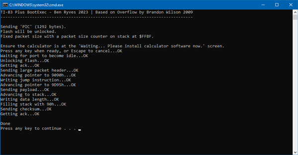
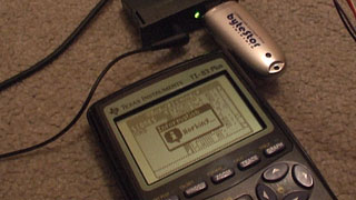
The previous release of the TI-83 Plus BootExec program relied on temporarily replacing TI's Silver Link driver with WinUSB if you wanted to use the Silver Link USB cable. I've updated the program so it will try to use TI's driver if it's available, or WinUSB if not. This should help people who can't (or don't want to) temporarily replace TI's driver.
The updated application can be downloaded, as before, from the same link: ti83p-bootexec.zip.
Updated TI-83 Plus BootExec with USB "Silver Link" support
Sunday, 4th June 2023
This is a quick update to the TI-83 Plus BootExec program described in a previous journal entry. The program now supports the USB "Silver Link" cable (as well as the serial "Black Link" it previously supported) though to access the USB device you do need to temporarily replace TI's supplied driver with a generic WinUSB one which can be organised with Zadig.
The updated application can be downloaded from the same link as before: ti83p-bootexec.zip.
Unbricking a TI-83 Plus calculator with a link buffer overflow
Friday, 2nd June 2023
A few years ago I started running into problems with my TI-83 Plus graphical calculator. I was unable to install applications – it would keep locking up when "defragmenting". In the end I attempted to reinstall the operating system to see if that would cure matters, but that failed too and in the process left the calculator in a state where it wouldn't boot at all. Switching it on you'd be presented with a screen prompting you to reinstall the OS:
Waiting...

Please install
calculator
software now.
If you tried to install the OS over the link port it would switch to a progress screen but then get permanently stuck at the 0% mark until you pulled a battery out.
I eventually found a program called Overflow by Brandon Wilson which described similar symptoms and a possible cause – a corrupt certificate page. Considering the problems I'd been having with the flash ROM before attempting the OS reinstallation it seemed possible that my certificate page might have become corrupt and that was preventing me from reinstalling the OS.
The Overflow program describes a technique whereby it can transfer a user-supplied program to the target calculator by sending a very large variable packet and taking advantage of a lack of bounds checking in the calculator's boot code. Unfortunately, I was unable to get it to work on my TI-83 Plus, in spite of many repeated attempts. I eventually bought a replacement calculator, though being a newer model and built to a much cheaper standard I was always a bit disappointed that my original calculator was lingering, bricked, in a drawer.
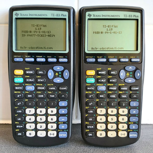
Photo of the repaired calculator (right) next to the its temporary replacement (left) – note the missing ID on the repaired calculator.
More recently I decided to revisit the problem, got a better understanding of just how the Overflow program worked and found a way to get it work on my original TI-83 Plus. The photo above shows the two working calculators I now have, though as I ended up having to erase the certificate page on the one on the right it now lacks an ID.
How Overflow works
The basic technique exploited here is that the TI-83 Plus boot code does not bounds-check the length of the link packet we're sending it, so by sending a very large packet we can overflow the intended buffer right up to user memory, send over a program we wish to execute, and then overwrite the Z80 stack with the address of our program so that when the link routines return it executes our program rather than returning to the boot code.
Overflow satisfies this process by filling up the memory as described above, then sending some correcting data so that the checksum for the oversized packet is equal to zero, and then sending a constant stream of zeroes until the transfer fails. The last two bytes of a transfer are the checksum, and by previously correcting the packet's checksum to zero this means that the packet will be seen as valid.
At this point the transmitting calculator detects the link error and tries to read back the acknowledgement from the receiving calculator, and all should be well.
Unfortunately, the TI-83 Plus seems to be more fussy about how it handles linking errors and once the attempt to send too many zero bytes has failed it just displays an error message and switches off, rather than letting us receive the acknowledgement before executing our payload.
Looking at the documentation for Overflow it seems to have been intended more for the TI-84 Plus series calculators,
so it could be that they are more forgiving of the linking errors.
Trial-and-error with zero padding
If the problem is that we're sending too many zero bytes, one option is to count how many zero bytes we can send successfully. Once the attempt has failed, we can then make sure that on our next attempt we only send just the right number of zero bytes (based on our previous count) and no more, then check for the acknowledgement from the receiving calculator. To my delight this strategy works well, and is provided by the application's -zeropad option.
Unfortunately as over 30,000 zeroes need to be sent each time the exploit packet takes a long time to transmit and as we now need to do it twice this can really slow things down! Once a safe number is known this can be specified with -zeropad=<count> but it's still a time-consuming process.
Fixed-size packets for quicker transmission
The problem here is not knowing the size of the packet we're transmitting. The packet does start with a length parameter, however as the "number of bytes left to receive" counter is stored on the calculator's stack by the receiving routine we end up overwriting that with our exploit payload and the total number of bytes left to receive will end up depending on the particular stack level at the time.
In my testing the variable ends up being stored on the stack at the same address ($FFC1 for normal transfers, $FFBF for ones where the flash was previously unlocked). Knowing this means that as we trample over the stack deploying our exploit we can at least make sure that we leave that value in the state it should be for the current point in the packet transfer.
This is implemented in the program with the -fixed parameter, which executes much more quickly than the -zeropad one and only needs to run through once. It is however reliant on knowing exactly where on the stack the "number of bytes left to receive" variable is stored; if it's different from the two presets baked into the program it can be changed with -fixed=<hex addr>.
The program itself
In case it helps anyone else out, the program can be downloaded from this link. It's a .NET application and requires a computer with a serial port and a "black link" compatible serial cable (I use a home-made cable), which I appreciate is not exactly the most modern solution but is what I have access to.
It will allow you to transfer a standard "noshell" TI-83 Plus assembly program to the target calculator, with or without flash unlocked. As this is a potentially risky operation (especially with flash unlocked, which would allow you to completely brick the calculator by damaging the boot code) any such programs are left as an exercise to the user to be used at their own risk. The original Overflow program contains much more useful information, including a sample program that can erase the certificate page, though be warned that as written is is not designed for the TI-83 Plus and will erase the wrong page and so will need to be modified before use. This is only recommended as a last chance for calculators that are otherwise bricked and unusable!
Update 4th June 2023: The program now supports the USB "Silver Link" cable, though you will need to temporarily replace TI's driver with a generic WinUSB driver using Zadig. The download link is the same as before.
Update 7th June 2023: The program will now try to use TI's driver for the "Silver Link" USB cable, if available. This avoids the need to temporarily replace it with the WinUSB driver.
Take your TI-83 Plus online with a TIWiFiModem
Monday, 27th March 2023
One of the issues holding me back with my development of the Light Gun Commando project (aside from a lack of free time due to the day job) was running out of prototyping breadboards and the difficulty of swapping between different console adaptor boards for testing.
Normally by this point I'd have started soldering together more permanent prototypes on little circuit boards, but I've been having a difficult time with the boards I've got in stock apparently being made of a metal that's impossible to solder to. They were very cheap, but for some reason the solder joints would end up coming out blobby, make poor connections, be prone to bridges and generally not "wetting" the pads at all. This makes hardware prototyping very frustrating and time-consuming, and though I'd tried different solder (no change), different temperatures (higher heats just meant the pads would unglue from the board more quickly), more flux (just more cleaning required afterwards) and other attempts to clean the boards before use (including light sanding) I wasn't getting very far.
I eventually bought a set of new circuit boards from a more reputable seller but before cracking on with my light gun adaptors I thought I should try a more straightforward weekend project and I ended up building myself a RetroWiFiModem.
This is a device that looks like an old dial-up modem and though it does have an RS-232 serial port on the back to connect it to a computer it doesn't attach to a phone line but instead connects to a modern Wi-Fi network. You can send it Hayes-style AT commands and "dial out" to a domain name which will then open a Telnet (or raw socket) connection to the remote computer and allow you to exchange data. As long as your old computer has a terminal emulator on it you can use this to connect to and browse online services such as BBSes.
I had a lot of fun building this and setting this up – especially as I can confirm that the circuit went together extremely easily on my new prototyping circuit boards – and it reminded me that I'd seen a terminal emulator program for the TI-83 Plus calculator around 20 years ago by the name of Telnet 83 Plus. The documentation accompanying the program had lots of information in it about how to connect to a modem using the calculator's grey serial link cable which directly translates the calculator's link protocol to true 9600 baud RS-232, unlike the black cable which I owned which just uses the control lines to bit-bang the calculator's link protocol. As I never had the equipment for this the program only ever ended up being a curiosity to me, but having seen how well the RetroWiFiModem worked I thought it could be adapted for use on a calculator.
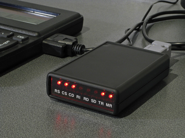
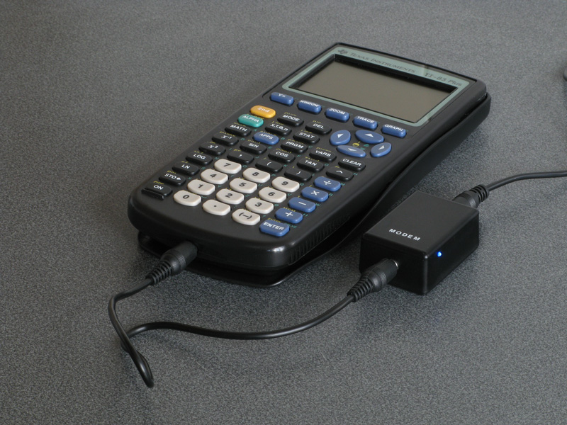
To do this I wrote a simple implementation of the calculator's link protocol in a class that inherited from the Arduino's Stream class. This is the same class that the Serial class inherits from, so having done that all I needed to do was a find-and-replace of Serial.* in the original source code with tilp.* and I had a version of the RetroWiFiModem that worked when connected to a calculator. As I also wanted this version to be a little more pocket-sized I designed it around the cheap ESP-01 or ESP-01S modules, which lacks the pins to drive the status LEDs on the original version so this ended up being a slightly more slimmed-down version of the project. It still has all the networking features, though, and the end result is the TIWiFiModem:
To interact with the modem I was using Telnet 83 Plus however I'd encountered a few bugs with this program, including incompatibility with newer TI-83 Plus calculators with slower display drivers (resulting in a scrambled image on the LCD), a lack of overflow checking on the receive buffer that would cause it to truncate long transfers and the inability to type certain keys in uppercase. Fortunately the source code was included so I dusted off my Z80 assembler and fixed these issues, along with shaving a few thousand bytes off the program size, improved compatibility with some VT100 sequences, a mode that automatically keeps the cursor within the view of the screen and local echo. These changes, along with the firmware for the modem, can be found on the TIWiFiModem Github page.
If you'd like to see what the TIWiFiModem is all about before building one yourself, I put together a video demonstrating it which is embedded above.
A larger level, moving sectors and failed optimisation attempts
Monday, 29th November 2010
I've made a few attempts to boost the performance of the 3D engine for the TI-83+ I'm working on with little success. I had previously failed to get any improvement by adding bounding boxes around each BSP node (the idea being that if a node falls outside the view you can discard it and, by extension, all of its children) but the act of transforming the bounding box to determine whether it was inside or outside the view was more CPU intensive than blindly handling the nodes whether they were inside the view or not.
A simpler test, I reckoned, would be to use bounding circles. These only have one point to transform, and determining whether they are in the view is one comparison to ensure that they're in front of the camera followed by one multiplication (by the constant √2) and two more comparisons to determine whether they are to the left or right of the camera's view; far simpler than a bounding box!
The bounding circles did cut down the number of BSP nodes that were handled each frame but the additional checks made the engine slightly slower in general than it had been before. In some circumstances it was slightly faster, but not enough to make a noticeable difference. The additional data per BSP node added over 900 bytes to the level data, too, so the attempted optimisation had to go.


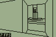


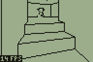
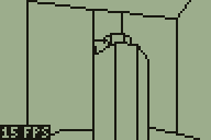
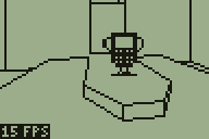
The newly added rooms to the demo level
One tweak that did boost performance noticeably was to cache the projected X coordinate of each vertex. All vertices in the map have at least two walls connected to them and so are projected to the screen at least twice if within the view. I already had a table that was used to indicate whether a vertex had been transformed around the camera or not that frame so it was easy enough to add the X coordinate of the projected vertex to that table, adding around a 15% boost to the framerate.
Points are projected to the screen by dividing their X (left/right) or Z (up/down) component by their Y (depth) component. Division is slower than multiplication so I tried to calculate the reciprocal of the depth for the vertex then perform all subsequent projection operations by multiplying the X or Z component by this reciprocal. Unfortunately, this resulted in a lack of precision owing to my use of 16-bit fixed-point numbers (walls "wobbled" as you moved the camera) and performance was about the same as it had been before, so I rolled back the changes.
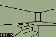
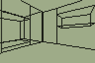
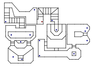
The block of screenshots in the above text shows a new region that has been added to the demo level, and the image below is a map of that level — fans of DOOM may notice that it's based on a small portion of E2M7 (The Spawning Vats).
Map of the level
This level now uses every one of the 256 walls that are available, so is probably a good indication of the maximum size of a single level (and at 6,626 bytes it's certainly rather taxing on the limited amount of memory in a TI-83+ calculator).
This is, however, the maximum size of a single level. It does not take long to load and unload levels, so it would be quite possible to construct a continuous level that appears larger by unloading the current one and loading a different one when the user moves to a particular region. This could be implemented in an obvious manner (such as the player stepping into a teleporter) or transparently (by moving the player into an identical copy of the room he left to hide the transition). The latter option also introduces the option of level geometry that would otherwise be impossible in a 2D-based engine, such as rooms above rooms. Special effects could also be tried, such as an infinite corridor that warps you back to the beginning when you reach its end.

However this feature is implemented, there would need to be some way to trigger the action. The above animated screenshot demonstrates the current trigger system which is used to set a sector in motion. A sector, in this instance, is a region with a particular floor height and ceiling height. Each wall indicates which sector is in front of it and which sector is behind it. Convex sub-sectors contain sets of walls and also indicate which sector they are part of, and are attached to the leaves of the BSP tree. Given a point, you can quickly find out which convex sub-sector it is in by walking the BSP tree. When you have found the convex sub-sector you can then look up its sector. This is currently used to set the player's height, as the sector tells you the floor height.
If you keep track of the player's sector each frame you can tell when they have moved from one sector to another. This then fires an event, reporting which sector the player used to be in and which they are in now. In the above screenshot, the platform is set to descend whenever the sector surrounding it is entered from any sector other than the platform itself (this is to stop it from automatically descending when the player walks off the top of the raised platform). It is also set to rise whenever the platform's own sector is entered. This produces a simple lift; doors are handled in a similar fashion elsewhere in the level.
If you'd like to try this demo on your calculator, you can download the binaries for the TI-83 and TI-83+ in Nostromo.zip. As ever, please back up any important files on your calculator before running the demo; it may well clear your RAM. For those without calculators, an animated screenshot is available.
Collision detection makes the world feel solid
Sunday, 21st November 2010
One of the larger problems with the 3D engine for the TI-83+ calculator series I have been working on is that it's possible to move the camera through walls. This doesn't make the world feel especially solid, so I've started working on some collision detection routines.
Work commitments have left me with little time to spend on this project over the last couple of weeks so progress has been very slow, but I've got a basic collision detection system mostly working.
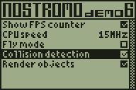
I spend most of the above screenshot running into walls. The code seems to work relatively well and quite quickly, though it's far from perfect. The still image shows the new settings screen, which is hopefully a little easier to use than remembering which keys do what. It also has the advantage of displaying the state of the current settings.
The walls are stored as line segments between two 2D vertices, and the collision detection has to ensure that the player does not get too close to any of these walls. The technique I have used starts by calculating the closest point on the line to the player.
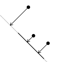
The above image shows a wall (the solid line segment) and three possible player positions (the heavy dots). The arrows point to the closest point on the wall's line. The closest point on the line to the top player position is past the end of the line segment, so it is ignored. The other two closest points lie on the line segment, so these are checked in more detail.
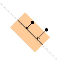
The distance between the closest point on the line and the player position is then calculated and compared to a threshold value (the radius of the player). The above image highlights the out-of-bounds region in tan. The lower player position is outside this region so is ignored, but the upper player position is inside it and needs to be corrected.
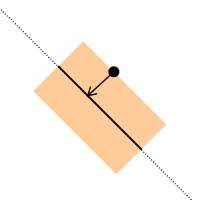
The correction is quite straightforward. We know the closest point on the wall to the player. The angle of the wall's normal is stored in the level file, so we can easily calculate a vector from that to push the player a fixed distance away from the wall.
In addition to the above 2D checks, a very simple height check is performed for "upper and lower"-type walls. These are walls with a central hole so you can pass over or under them, and are used to connect sectors with varying floor and ceiling heights. The top of the player's head is used to check the ceiling height. Rather than use the height of the player's feet to check the floor height their knee height is used. This is to allow the player to climb low walls (such as the edges of steps).
When I first implemented these collision detection techniques I checked every wall in the map. This halved the framerate in places, and as the framerate is not particularly high in the first place I needed to find a way to reduce the number of tests. Taking further inspiration from DOOM I implemented a "blockmap". This breaks the map down into square blocks and each block contains a list of which walls pass through it. To perform collision detection I look up which block the player is in and from that I can retrieve a reduced list of which walls they may end up walking into. The original implementation had to check well over a hundred walls for each movement; the blockmap reduces this to 26 in the worst case scenario for the current level design.
Sadly, this additional blockmap enlarged the size of the map quite a bit, so I've attempted to reduce it a little. For simplicity and performance most structures referred to other structures by pointer (for example a sub sector contained a list of pointers to walls and each wall contained pointers to a front and back sector). I've changed most of these to now refer to other structures by index, which shaved a few hundred bytes off the map at the cost of a few hundred clock cycles. Overall performance still isn't great, though I haven't found it noticeably slower than the previous demos.
I added very primitive physics for moving the player up and down relative to the floor to complement the collision detection. This retrieves the floor height from the sector directly under the centre of the player and compares it to the current player height. If the new floor height is higher than the old floor height then the player's foot height is set to a point half way between the two; this smoothes the animation slightly when climbing up stairs (rather than just snapping to the new floor height). When moving from a higher floor to a lower floor the player's downward speed is increased to roughly simulate gravity.
A demo for the TI-83+ series and TI-83 can be found in Nostromo.zip. As always, this is a piece of software in development and there may be calculator-crashing bugs, so please back up any important files before running it.
Enlarging the world
Sunday, 7th November 2010
There have been very few changes to the features of Nostromo recently. I have tried a number of ways to optimise the performance and whilst the handful of micro-optimisations I have made have boosted the frame rate a little none of the higher-level optimisations have done much. I did try, for example, storing a bounding box around each BSP node and ignoring it (and all its children) should this bounding box fall outside the field of view; the additional code to check the bounding box ended up halving the framerate rather than improving it.


I have, however, enlarged the level quite considerably. A staircase connects the central room with the pit to a rather strangely-shaped arrangement of walls (again copied from E2M7). The room with a pit continues to cause issues; looking across it towards the room with the small central staircase forces the engine to step through a very large number of convex sub-sectors and check many walls. This drops the frame rate down to about 3 FPS on a TI-83+. However, this is specific to that room; the newly-added rooms have not noticeably affected the frame rate in other parts of the level.
Another minor improvement is that the engine now supports different sprites. I'm not too good at drawing them, as you can probably tell from the above screenshots, but at least the code is there to support them.
You can download a TI-83 and TI-83+ binary to try the demo on your calculator (please back up any important files first). Alternatively, here is an animated screenshot.
Adding sprite objects to the 3D world
Tuesday, 2nd November 2010
The previous entry showed a room from a map copied from DOOM's E2M7. I have since added the adjacent room:
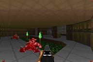

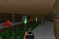

It may not look as interesting as the other room but it is significantly more costly to render due to the sheer number of lines visible at a time in it. Looking across it from the far corner dropped performance down to around 2 FPS on the 6MHz TI-83+, which was really not a very good effort. I spent a fair amount of time over the weekend trying to optimise the code as much as I could, and manage to bring the frame rate in the player's starting position from 6 FPS up to the target 10 FPS. Looking across the length of the new room still dropped the framerate to around 4 FPS at 6MHz, but it's a start.
Once the engine had been made a little faster it seemed a good idea to slow it back down again by adding a feature. I had been pondering how to add objects in the form of scaled sprites to the world. Working out where to put them on the screen isn't so difficult, but clipping them against the world geometry so that they couldn't be seen through walls is another matter entirely. One way that seemed popular is to draw the objects in reverse depth order (drawing the sprites that were further away before those that were closer) and using a depth buffer for the world geometry to clip each pixel of the sprite against the world. This would take up a lot of memory on the calculator and run very slowly (populating the buffer with a depth value for each pixel would be a very expensive operation, as you'd have to interpolate depth values between the ends of walls and edges of floors).
The engine makes use of three per-column clipping tables when rendering the scene. One keeps track of columns that have been completed (usually by drawing a "middle" wall to that column); once completed no more pixels may be drawn to that column. The other two tables are used to define the upper and lower clipping bounds. At the start of the scene these are reset to the top and bottom edges of the display. As the world is rendered from front-to-back these regions are reduced to clip geometry that is further away against geometry that is nearer (think of looking through a hole in a wall — things that are further away from you will never be drawn in the space above or below that hole).
Fortunately, you can use this clipping information to clip sprites against the world geometry too. Each sprite object needs to be associated with a convex subsector. These subsectors are made up of walls and are drawn from front-to-back (sorted by the BSP tree) as the world is rendered. Before each one of these subsectors is drawn it is checked to see if it contains any sprite objects — if it does, the current clipping buffers and a reference to the subsector are pushed onto a stack. When all of the walls and floors have been drawn this stack contains a list of all of the subsectors containing sprites and the clipping regions used to draw those subsectors in front-to-back order. Stacks are Last In, First Out structures and so when you pull the data back out of this stack you end up retrieving a list of sprites to draw and the associated clipping regions in back-to-front order. This allows you to effectively unwind the clipping operations, so as you draw the sprites from back-to-front you can gradually enlarge the clipping regions in the opposite order to the way that they were reduced when drawing the walls. You would still need to sort the sprites manually from back-to-front within each subsector, but for the time being I've limited myself to one sprite per subsector for ease of development.
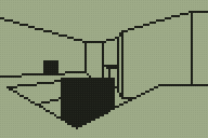
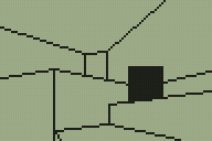
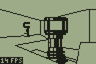
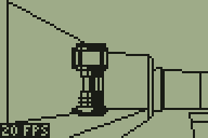
The above screenshots demonstrate an initial test of the "things" (as they are apparently technically called), rendering them as solid black squares.
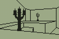
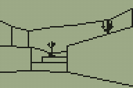
Scaled sprites tend to be more useful than solid black squares, however, so here are a pair of candlesticks (well, that was the intention at any rate; call them cacti if you must). The sprite was simply ORed to the display, so pixels could be black or transparent.
I then added support for "white" pixels too. The above screenshot is a link to an animated GIF showing the engine in action. The sprites appear to jiggle up and down and have invalid data drawn underneath them in places, which was caused by my accidentally overwriting an important register before rendering each column (fortunately an easy one to spot)! The relatively high frame rate in the above image was helped by running at 15MHz and using the old single-room map.
The above screenshot (click for the animated GIF) fixes the dancing sprites and restores the second room, though is still running at 15MHz. For a bit of fun I added animated doors; all this does is adjust the floor heights of the sectors used to represent "doors" (pressing Alpha will toggle both doors open or shut) but it makes the world look a little more dynamic.
There are still some rendering bugs in the engine. The above animated screenshot demonstrates one; when close to a wall edge you will sometimes see a temporary vertical line the height of the screen or the screen will flash white. I reckon this is probably an integer overflow issue causing the projected height of a line to be on the opposite side of the screen than the one it should be (the bottom edge of a hole in a wall may be projected above the screen rather than below it, causing the entire screen to be clipped out, for example). One bug that took a while to identify (it only appeared in very particular positions; moving one unit in any direction cured it) was caused by truncating a 32-bit integer to a 24-bit one. When viewing a long wall from a long distance the result of a 16-bit (difference between end and start X coordinates) by 16-bit (Y coordinate of the start of the wall) multiplication was resulting in a value of $00800000 or so (a large positive number). When truncated to 24 bits this becomes $800000, which has the most-significant bit set and was therefore treated as a large negative number. As this was part of the wall clipping code it would end up clipping a wall end a long way behind the camera instead of within the view; fortunately this obvious mistake is easy to spot and correct (the answer can only be positive, so if you get a negative one just negate it).
If you'd like to try the demo on your own calculator please download Nostromo.zip. As this is a work in progress there are likely to be bugs so please back up any important files first!
Adapting a room from DOOM's E2M7 to the TI-83+ calculator
Thursday, 28th October 2010
The level I've been working with as a test for the TI-83+ 3D engine was something I quickly threw together. I've never been much good at the design side of things, and my lack of imagination was producing something very simple that wasn't really challenging the engine and testing whether it could be used in a game. Looking for inspiration, I played through map E2M7 in DOOM and found a fairly interesting room to try to convert.
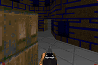

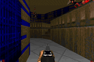

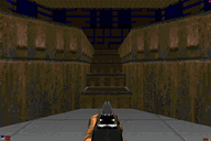

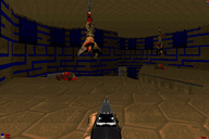

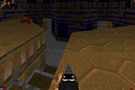

I'm sure you can tell which is the original room from DOOM and which is my adaptation of it.
Since the last post I have had to make quite a few tweaks to the engine. In the previous build there was a bug which cropped up when the top or bottom edges of walls appeared above or below the screen bounds. This turned out to be caused by a routine that was intended to clip a signed 16-bit integer to the range 0-63; it would return 0 for values 128 to 255 instead of 63. Fortunately this was an easy fix.
Another bug was in the way "upper and lower" walls were handled. Sectors have different heights and "upper and lower" walls go between two adjacent sectors and connect the ceiling of one to the other and the floor of one to the other, leaving a gap in the middle.
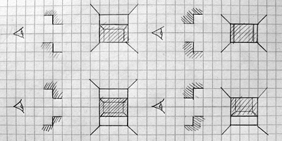
The above picture shows the four main types of sector-to-sector transition through an "upper and lower" wall type. Different transitions require different numbers of horizontal wall edges to be traced; in the bottom left example (going to a sector that has a lower ceiling and higher floor than the current one) four lines would be required and in the top right example (going to a sector that has a higher ceiling and lower floor than the current one) two lines would be required. The previous version of the engine always drew four lines, which would produce a spurious line above or below the "hole" for three out of the four different combinations of sector-to-sector transition. By comparing sector heights the right number of horizontal lines can be drawn, which greatly improves the appearance of the world and slightly increases the performance, too.
A less immediately obvious limitation was in my implementation of the BSP tree structure. Each node on the tree splits the world geometry into two halves; one half is in "front" of the partition and the other is "behind" it. Each chunk of split geometry can be further subdivided by additional partitions until you're left with a collection of walls that surround a convex region. You can then walk the tree, checking which side of each partition you are on to determine the order that the walls should be rendered in. For more detailed information the Wikipedia article on binary space partitioning is a good starting place but the basic requirement is that you should be able to slice up level geometry into convex regions with partitions. I had naïvely assumed that horizontal or vertical partitions would be sufficient (and they are useful as you can very quickly determine which side of a horizontal or vertical line the camera is on). However, this room demonstrated that such a limitation would not be practical.
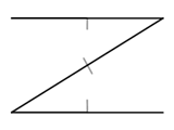
Consider the above geometry. The black lines are walls and the small grey lines represent the wall normals; that is, the walls face the inside of the "Z". The wall in the middle is double-sided; you could put the camera above or below it and see it. However you slice that map up with horizontal or vertical partitions you will still end up with regions that are not convex.
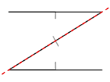
A single partition along the central wall divides the map into two convex regions. I had initially thought that checking which side of such a partition the camera lay would be an expensive operation, but it's not too bad; as a line can be represented by the expression y=mx+c I can store the gradient m and y-intercept c in the level data and simply plug in the camera's x and compare to y to determine the side. A single multiplication and an addition isn't too much to ask for.
Fortunately, there are only two of these partitions in the level!
I have added some other features to the demo program. Pressing Zoom when using a calculator that can run at 15MHz (a TI-83+ SE or any TI-84+) toggles the speed between 6MHz and 15MHz. Pressing Mode or X,T,Θ,n allows you to look up or down. Pressing Window toggles between the default free movement and a mode which snaps you to a fixed height above the floor. These additions are shown in the below screenshot (click to view the animation):
Unfortunately, performance is lousy. Viewing the stairs drops the framerate to a rather sluggish 6 FPS when running at 6MHz (most of the above screenshot is recorded at 15MHz). The LCD's natural motion blur helps a little (it feels a lot more fluid on the calculator than it does on a PC emulator) but I'm aiming for a minimum of 10 FPS, so I need to make quite a few optimisations. There are several low-level ones that could be made; for example, when clipping the 2D line segments to the display I'm using a generic line clipper that clips the line both horizontally and vertically. As wall has been clipped to the horizontal field of view by that point I only really need to clip it to the top and bottom edges of the display. There are also some high-level optimisations to be made; for example, double-sided walls are currently stored as two distinct walls with the vertex order swapped. This means that to handle both sides of the wall the engine has to clip and project it twice, which involves lots of expensive divisions and multiplications. The results of these operations could be cached so that they only needed to be calculated once.
A TI-83 and TI-83+ binary is available if you'd like to try the demonstration on your calculator: please download Nostromo.zip. The usual disclaimers about backing up your data before running the program apply!
Varying wall heights in a 3D engine for the TI-83+
Monday, 25th October 2010
I've done a little more work on the 3D engine for TI-83+ calculators that I mentioned in the previous entry. The main difference is in limited support for varying the heights of floors and ceilings, illustrated in the following screenshots.


Walls now refer to one or two "sectors". A sector is a 2D region of the map of any size or shape; it can be concave or even have holes in it. Walls are also grouped into convex regions named subsectors for rendering purposes. Each wall has a sector in front of it and a sector behind it; these sectors have a specified floor and ceiling height. There are now two types of wall; a "middle" wall which connects the floor and ceiling of the sector in front of it and an "upper and lower" wall which connects the ceilings of the sectors on each side and the floors of the sectors on each side.
This makes occlusion a little trickier and determining where to draw lines around the edges of walls even more so!
The previous version of the renderer worked by drawing walls back-to-front, clearing rectangles the height of the screen behind the wall segments as they were drawn. The first attempt to improve this exchanged rectangles the full height of the screen with trapezia. The screenshot to the left shows the bounding rectangle around each wall segment being filled and the one to the right shows each wall filled as a trapezium. (As before, clicking an image with a border will display an animated screenshot).
Rather than attempt to calculate where lines should be drawn around wall edges I thought I'd experiment with dithered wall fills instead. The left screenshot shows this addition (each wall has a different shade) and the right screenshot shows the addition of support for wall heights (still drawn in the simple back-to-front technique, resulting in significant amounts of overdraw).
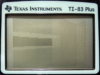
Unfortunately, the LCD on the calculator copes rather poorly with dithered fills; the above photograph was taken at the highest contrast setting. Rotating the camera to look at walls with a different dither pattern brings the world back into view. This is rather unacceptable, and is something I ran into with my previous implementation. I think I'll stick to stroked wall outlines rather than filled walls.
I had been experimenting with a new level design in the C# prototype of the engine that added another room accessible via a tunnel from the starting room. I added some code to the C# program to output the level data in a form that could be assembled into the Z80 version. This is shown above, having reverted to a simple wireframe view in anticipation of the new wall drawing code.
The new way to implement occlusion works very differently to the previous one. I had been sorting the geometry from back-to-front and rendering it in order, drawing walls in the foreground on top of walls in the background. This wasn't very efficient and wouldn't scale well. The new approach renders from the front to the back and works on information stored about each column of pixels on the screen. The screen is 96 pixels wide, so there are 96 columns to deal with. A counter is set to 96 at the start of rendering. When a column of a wall is rendered, a flag is set to indicate that that column has been completed and the counter is decremented. When the counter reaches zero, that means that every column on the screen has been completed and the renderer terminates. This is demonstrated in the above screenshot when compared to the previous one; walls that are some distance away from the camera (and behind other wall segments) are not always drawn as the renderer has decided that it has finished before reaching them.
An obvious issue with the above screenshot is that even though some of the geometry is culled, individual walls can still be seen through other ones.
Part of the solution is to use a custom line-drawing routine that checks each pixel against the completed columns table. If a column is marked as completed, the pixel is not drawn; if it isn't, the pixel is drawn. This is shown above.
I previously mentioned that there were two types of wall; "middle" walls (solid ones from the floor to the ceiling) and "upper and lower" ones (these have a hole in the middle). Only "middle" walls flag a column as being completed, as you need to be able to see through the hole in "upper and lower" ones. This causes the rendering bugs in the previous screenshot above and below the holes in the wall. The way to fix this is to add two new per-column clipping tables; one which defines the top edge of the screen and another which defines the bottom edge. These both start at the maximum values (0 for the top edge and 63 for the bottom) and are reduced whenever an "upper and lower" wall type is encountered.
The new code to do this is demonstrated in the above screenshot. There is still, however, a bug in this implementation. The per-column clipping tables are updated by the code that draws the line along the bottom or top edge of the hole in the wall. If this line is partially (or completely) off the screen, these tables are not updated and the rendering bugs appear again (as demonstrated at the end of the above screenshot). A final manual pass over parts of the line that are clipped off the screen corrects the issue:
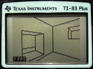
As can be seen in the bottom left corner of the above screenshot I have added an FPS counter. This is accompanied by code that scales movement by elapsed time so you move at the same speed regardless of how long each frame takes to render. The engine is quite slow (and could no doubt be heavily optimised by someone who's good at assembly) and has quite a few bugs in it but it's certainly looking a little better than it did a week ago. As I only have a regular TI-83+ I'm aiming for something usable at 6MHz; the more modern calculators can run at 15MHz but this feature is not used in the demo.
For those interested in trying the demo on their calculators, click on the above image to download an archive containing a TI-83+ and TI-83 binary. As before, this is experimental and may well crash your calculator, so please back up any important files first!
A primitive 3D engine for the TI-83+
Sunday, 17th October 2010
As you may have guessed from the number of spinning cubes in my projects, I am quite fond of primitive 3D. As you may also have guessed from the number of TI-83+ calculator projects I have undertaken, I'm also quite fond of programming on low-end machines. I have never really successfully put 3D and the TI-83+ together, though.

One way to build a 3D world in software is raycasting (e.g. Wolfenstein 3D). This typically results in blocky worlds where all walls are at 90° angles to each other. There are several games using raycasting engines on the TI-83+ already; they are much faster and better-looking than my sorry attempt pictured above.

Another method is to use true 3D geometry (e.g. Quake). Many years ago I attempted to work on something that looked a little like Quake. I built this on the Matt3D engine, which supported basic 8-bit coordinates and lines, but not solid objects. The result was even less useful than the above raycaster!

Another method somewhere between the two is a "2.5D" engine, where level geometry is defined between points in 2D space but projected in 3D (e.g. DOOM). This allows for walls that are not at 90° angles to each other, whilst simplifying the rendering procedure significantly. I spent some weeks working on such an engine a few years ago yet never managed to get any further than the above screenshot. As you can probably tell from the fact that you can see the walls through each other I never found a good way to handle occlusion, and the project ended up stagnating.


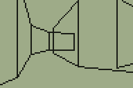
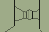
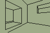
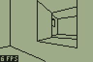
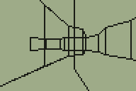
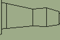
Looking for a quick weekend project I thought back to the work I'd done with the DOOM and Quake engines. These engines use a BSP tree structure to sort the level geometry for rendering. I reckoned that if simplified a little a similar tree structure could be used to render a 3D world on the TI-83+ calculator. The four screenshots above show that this technique is indeed quite successful. My implementation could certainly do with a lot of work but I think the theory is at least sound.
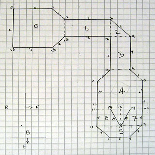
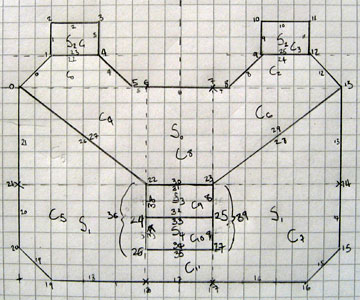
I decided that one way to make this project a bit more fun was to set myself a challenge; to design a level that I would, ultimately, be able to walk around in. This level is shown above, and contains a number of walls that are not parallel to the X or Y axis and a pillar. I have split the world into eight convex "sectors" (labelled 0 to 7) with a dotted line between them to show where the BSP tree is partitioned. All of the partitions are either horizontal or vertical to speed up tree traversal; the TI-83+'s Z80 CPU does not support floating point arithmetic, let alone multiplication or division, so being able to decide which side of a partition you're on quickly is very useful.
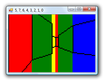
Rather than dive straight into Z80 assembly programming I knocked together a quick prototype in C#. This allows for quick and easy debugging; the blocks of colour allow me to quickly identify walls and the application title bar contains the order in which the sectors have been rendered. These can then be checked against the version running on the TI-83+ in case there are problems.
With the C# version running satisfactorily I started converting it to Z80 assembly. The above screenshot shows the first step; transforming the level's vertices around the camera. Clicking on the screenshots will take you to an animated version; as some of them are quite large I have linked to them rather than embedding them directly.
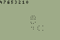
The next step was to traverse the BSP tree. The numbers across the top of the screen indicate the order in which to render the sectors, from back to front — however, due to a simple bug, they are actually listed from front to back. This was fortunately very easy to fix.
Walls are connected between the vertices, so I quickly threw something together to display all of the walls on the screen. The walls will have to be clipped against the camera's view (or discarded entirely if they are outside the view) so being able to see them is a great debugging aid!
We are only interested in drawing walls that are in front of the camera, so the first bit of clipping code deals with clipping the walls against Y=0.
The above screenshots show the final three stages of clipping to the camera's view, defined by Y>0, Y>+X and Y>-X. The first screenshot shows culling of any wall that does not satisfy this in any way; walls that are completely outside the view are discarded. The second screenshot shows walls being clipped against Y=+X, and the third finally adds clipping against Y=-X. The lack of hardware floating-point arithmetic makes the code fairly slow and ugly but it does seem to be working relatively well.
We are only really interested in dealing with walls that are facing the camera; we don't want to draw the back of walls. To work out which we want to keep and which we want to ignore, we project the wall to the screen and check whether its projected start vertex appears to the left or the right of its end vertex.
A simple perspective projection is performed to turn this clipped 2D world into what appears to be a 3D one. The X coordinate of each vertex is divided by its Y to get the X coordinate on-screen and the height of the wall is divided by the vertex Y to get the Y coordinate on-screen. The left screenshot shows the top and bottom of wall edges; the right screenshot adds lines between the floor and the ceiling to produce a more convincing "wireframe" view of the world.
The final step is to make the world appear solid, by hiding walls that are far away behind walls that are closer to us. Traversing the BSP tree gives us the order in which to draw the walls, so all that is required is to draw solid quadrilaterals for each wall rather than the lines around its outside. A fast clipped quadrilateral filler would take me some time to write so I cheated by drawing a solid white rectangle the width of the wall and the height of the entire screen before drawing the wall outlines. As the camera is half-way up each wall and all of the walls are the same height there are no cases where a foreground wall only partially covers a background one so this trick works for the time being.
I'm glad I achieved my goal of walking around the 3D world I'd sketched in pencil at the start of the weekend but I'm not sure where I'll be able to take the project now. Turning it into a useful 3D engine for a game would certainly require a lot of work. The level and its BSP tree were generated by hand, which would not lend itself well to anything but the simplest of levels. However, the lack of variation in wall heights produces fairly dull levels in any case; DOOM-style levels would be something to strive for, but I'm not sure how well the calculator would be able to cope with them. I'm also unsure how well the engine would scale; this very primitive version only achieves around 12 FPS on a 6MHz TI-83+. It's certainly given me something interesting to think about!
If you would like to try the program on your calculator, please download Nostromo.8xp. It requires an Ion-compatible shell to run. It is very primitive, likely to be quite buggy (you may encounter rendering bugs when very close to walls due to integer overflow in the clipping and projection code) and may well crash your calculator; please back up any important files before running it. Use the arrow keys to move around, Trace and Graph to strafe and Clear to quit.
TV Demonstrator for TI calculators
Monday, 11th October 2010
I've been tinkering with a number of small projects recently. I've resumed work on an LED clock for my bedroom (using a 32×8 LED display) and written an experimental BASIC interpreter in C# which I may try to turn into an assembler (implementing assembly statements as BASIC ones). In the mean time, I have finished one project — a device to display a calculator's screen on a television set.
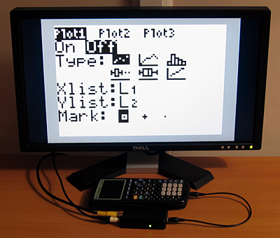
Texas Instruments also manufacture a product that allows you to view the screen contents of a calculator with supported hardware on a TV; here is a video demonstrating it. The additional hardware (either on special "ViewScreen" calculator models or built into the more advanced calculators such as the TI-84+) allows the device to mirror what is sent to the calculator's LCD in real-time.
I do not have one of these calculators, just a plain old TI-83+. However, this calculator (as well as the older TI-83 and TI-82) allows you to capture a screenshot over the link port. Pressing a button on my device captures a screenshot in this manner and displays it on the TV. This relies on the calculator being in a state where it can respond to these screenshot requests, so is not ideal, but considering that the TI Presenter costs $300 and relies on special hardware inside the calculator and mine should cost less than a tenth of that in parts and work with older calculators I think it's a decent compromise.
I had previously believed that NTSC composite video signals used a negative voltage for sync pulses. I have since found documents that indicate that the sync, black and white levels are the same as those for PAL. The timing is, naturally, different but as there's no need to change the hardware it makes supporting both NTSC and PAL relatively straightforwards. This contraption can be set to operate in either NTSC or PAL mode by sending the real variable M to it from the calculator, with a value of 60 for NTSC and 50 for PAL.
I acknowledge that this is not the most useful of projects (unless you're a maths teacher with an interest in electronics) but the code may be of interest for other projects. A handful of inexpensive parts can get you a picture on a TV from a 96×64 monochromatic frame buffer (the 1KB RAM on the ATmega168 doesn't allow for much more, alas).
More information and downloads can be found on the TV Demonstrator project page.
64-bit IThumbnailProvider, BBC BASIC matrices and clocks
Friday, 16th October 2009
Work commitments have left me with little time to pursue my own projects of late, hence the lack of updates.
A chap named Jeremy contacted me with problems relating to the IThumbnailProvider code I'd posted here before. We narrowed it down to a 64-bit issue, demonstrated by the fact that the thumbnails appeared in the file open dialog of a 32-bit application, but not in Explorer. Not having a 64-bit version of Windows to tinker with, I was unable to help, but he found the solution was to register the assembly using the 64-bit version of regasm. You can read more about his experiences on his blog.
I had made a mistake in the BBC BASIC (Z80) for TI-83+ documentation, describing the old coordinate system in the graphics documentation rather than the current one (which is more closely aligned to other versions of BBC BASIC). I have uploaded a new version of the documentation to ticalc.org. This build also includes some basic matrix operations via the MAT statement. This statement is rather incomplete, but I've run out of ROM space (not to mention time) to implement it fully. Still, the bits that are there are quite useful, and a half-arsed implementation is better than no implementation... right?
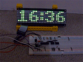
On a whim, I purchased a 32×8 LED display on eBay which I've (very) slowly been turning into a remote-controlled clock. A Sony-compatible remote control is used to type in the time, after which you can cycle through different styles with the channel up/down buttons and change the brightness with the volume and mute buttons. I'm using a 4MHz PIC16F84 to drive the display, with a DS1307 responsible for time-keeping and a 32KB 24LC256 to store the font data and text strings.
As well as dates and times, I thought a thermometer might be a useful addition so I put together an order for a DS18B20. It's silly to just order one thing, so I bulked up the order with one of the snazzy new PICAXE-20X2 chips (yes, they run a BASIC interpreter but the new 64MHz clock speed is certainly impressive). I find PICAXE microcontrollers invaluable for prototyping, being so very easy to use! ![]()
In an attempt to broaden my horizons, I also purchased two AVRs, as I have zero experience with these popular chips. I went for the two ends of the scale as offered by the supplier - an ATmega168 and an ATtiny13. Having lost a battle with PayPal's cart (it kept forgetting old items as I added new ones) I neglected to purchase a D-sub hood so I'll be waiting until I can go and buy one before I start assembling a programmer. I was intending on going for the simple SI Prog, but if anyone has any suggestions for variations I'd be interested in hearing them!
Nibbles and Logo
Thursday, 19th February 2009
Work on BBC BASIC has slowed down quite a bit, with only minor features being added. A *FONT command lets you output large or font sized text to the graphics cursor position regardless of the current MODE:

10 MODE 3
20 VDU 5
30 MOVE 0,255 : PRINT "Small"
40 *FONT LARGE
50 MOVE 0,227 : PRINT "Large"
60 VDU 4
70 PRINT TAB(0,3) "Small (VDU 4)"
Another new command is the dangerous *GBUF that can - when used correctly - let you switch the location of the graphics buffer. You can simulate greyscale by quickly flickering between two different images on the LCD, which is where this command may come in use.

Snake/Nibbles is a fun game and an easy one to write, so here's a simple implementation that features variable speeds and mazes. The game runs quickly on a 6MHz TI-83+, which I'm happy with. And yes, I know I'm terrible at it. ![]()
One thing I've always been pretty bad at is writing language parsers resulting in poor performance and bugs. I've started writing a primitive Logo interpreter in C# to try and improve my skills in this area. So far it supports a handful of the basic language features and statements:
- print [Hello World]
Hello World
- make "animals [cat dog sheep] show :animals
[cat dog sheep]
- make "animals lput "goat :animals show :animals
[cat dog sheep goat]
- print last :animals
goat
- repeat 2 [ print "A repeat 2 [ print "B ] ]
A
B
B
A
B
B
- show fput [1 2 3] [4 5 6]
[[1 2 3] 4 5 6]
- [10 9 8]
Not sure what to do with [10 9 8]
(No, no turtle graphics yet ![]() ). There's no support for infix operators yet. The BBC BASIC ROM manual describes the top-down parsing method it uses to evaluate expressions so I'm going to attempt to reimplement that.
). There's no support for infix operators yet. The BBC BASIC ROM manual describes the top-down parsing method it uses to evaluate expressions so I'm going to attempt to reimplement that.
One issue I've already run into are the parenthesis rules: for example the sum function outside parentheses only allows two arguments, but inside parentheses works until the closing parenthesis:
- print (sum 4 5)
9
- print (sum 4 5 6)
15
- print sum 4 5
9
- print sum 4 5 6
9
Not sure what to do with 6
I'm not sure whether a "this statement was preceded by an opening parenthesis" flag would be sufficient.
Extending BBC BASIC
Sunday, 1st February 2009
BBC BASIC may have originated with the 8-bit home computer era, but it's still being updated and its most up-to-date incarnation - BBC BASIC for Windows - has a wealth of features that are unavailable on the Z80 version.
The BBC BASIC graphics API is primarily accessed via the multi-purpose PLOT statement. PLOT is followed by three arguments - the type of graphics operation being carried out followed by an X and a Y coordinate. For example, to draw a line between (20,30) and (100,120) you could do this:
PLOT 4,20,30   : REM Move graphics cursor to (20,30)
PLOT 5,100,120 : REM Draw a line to (100,120)
This results in needing to remember a lot of different plot codes (there is a logic to how they are formed but I still need to consult a list of codes from time to time). All implementations of BBC BASIC feature two helper statements to aid the user:
- MOVE x,y (equivalent to PLOT 4,x,y)
- DRAW x,y (equivalent to PLOT 5,x,y)
More recent versions, such as BBC BASIC for Windows, also implements the following helper statements, amongst others:
- CIRCLE x,y,r (equivalent to MOVE x,y : PLOT 145,r,0)
- ELLIPSE x,y,w,h (equivalent to MOVE x,y : PLOT 0,w,0 : PLOT 193,0,h)
- FILL x,y (equivalent to PLOT 133,x,y)
- RECTANGLE FILL x,y,w,h (equivalent to MOVE x,y : PLOT 97,w,h)
This is all very well, but the BBC BASIC (Z80) interpreter is a sealed box as far as I am concerned. I can ask it to perform tasks for me ("evaluate this expression") and it can ask me to perform tasks for it ("output this character to the display") but I can't modify its behaviour.
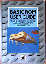 Or, so I thought - until I read through the copy of BASIC ROM User Guide that a friend had rescued and sent to me. It has a section on adding statements, which it achieves by using a clever - but simple - trick.
When BBC BASIC encounters a statement it doesn't recognise it triggers the Mistake error. On the BBC Micro the error handler is vectored, meaning that it loads the address of the error handling routine from RAM first instead of jumping to a fixed address. This allows the user to override the normal error handler, detect the Mistake condition and try and parse the erroneous statement themselves. If they can't handle the statement either control is passed back to BBC BASIC's usual error handler, otherwise the error condition is cleared and execution continues as normal.
BBC BASIC (Z80) follows the same procedure but with one major difference - the error handler routine is not vectored. Unfortunately, the only practical workaround I can think of is to patch the interpreter's error handler routine directly. Richard Russell somehow managed to add support for additional commands to the Z88 version via a patch that runs from RAM, but I haven't been able to work out how he managed to do that yet.
 The first series of additional statements I added were the graphics helper statements listed above, WAIT (which pauses execution for a certain number of centi-seconds) and SWAP which exchanges the contents of two variables. These are all relatively simple statements to implement as they do not affect the state of BBC BASIC in any other way; they perform a single, simple task then exit.
One of the more useful additions to more recent versions of BBC BASIC is the WHILE...ENDWHILE loop structure. A limitation of BBC BASIC (Z80)'s statement blocks is that their contents must be executed at least once, hence IF statements must fit on one line, multi-line procedures or functions should be placed at the end of the file after an END statement and REPEAT...UNTIL loops - where the looping conditional is at the end of the block, rather than the start - are provided. If a WHILE condition evaluates to FALSE, control needs to resume at the matching ENDWHILE. This is an interesting technical challenge, as it needs to handle nested WHILE...ENDWHILE stataments when searching through the code to find the terminating ENDWHILE, but appears to work pretty well now.
Another useful recent addition is EXIT (in three variations - EXIT FOR, EXIT REPEAT and EXIT WHILE) which breaks out of a loop structure. This has the same technical challenges as the WHILE...ENDWHILE loop structure (searching for the matching loop terminator) with the additional difficulty of unwinding the stack to the correct position.
By combining WHILE loops and EXIT WHILE you can simulate multi-line IF statement blocks, so
IF <condition> THEN <statements>
becomes
WHILE <condition>
  <statements>
EXIT WHILE:ENDWHILE
These additions are not without their downsides. Most of the statements supported natively by BBC BASIC (Z80) are represented by single-byte tokens, whereas these extensions are stored as ASCII text. This makes them take up more room in the source file and slower to execute (searching for and handling strings is a much more complex operation than searching for bytes). Using them makes your programs incompatible with other versions of BBC BASIC (Z80). I personally feel that these disadvantages are far outweighed by the advantage of easier to read code, however.
To round the entry off, have a fractal. ![]()
BBC BASIC for the TI-83+/TI-84+ beta release
Wednesday, 21st January 2009
Work commitments have prevented me from doing much on my own projects recently, but zipping up a few files to get BBC BASIC tested is not a time-consuming process so I've started to release test builds.
The documentation is available online. It's generated by a little tool I hacked together to turn a MediaWiki database into a CHM file.
I've had a few issues with the TI-84+ hardware, such as LCD corruption, difficulty in getting key presses to register and crashes when USB devices are unplugged. I think I've fixed the LCD and key issues by dropping the CPU speed down to 6MHz when the full 15MHz is not required, but am still stumped by the USB issues. Unfortunately documentation on the USB hardware is rather thin on the ground and I don't own a TI-84+ for testing.
The package comes with a few demo programs from the CP/M release and a few I cobbled together myself. Most recently I've tried putting together a few little graphics demos.
There's still a fair amount of work to go on this project (especially optimising - some of the code is extremely inefficient) but it feels nice to have something out there for people to try. ![]()
Controller input updates to Cogwheel
Monday, 5th January 2009
I hope you all had a good Christmas and New Year period!
I received an Xbox 360 controller for Christmas, so have done a bit of work on Cogwheel to add support for it. (You can download a copy of the latest version 1.0.2.0 with SlimDX here).
The first issue to deal with was the D-pad on the Xbox 360 controller. When treated as a conventional joystick or DirectInput device the D-pad state is returned via the point-of-view (POV) hat. The joystick input source class couldn't raise events generated by the POV hat so support for that had to be added. This now allows other controllers that used the POV hat for slightly bizarre reasons (eg the faceplate buttons on the PlayStation controller when using PPJoy) to work too.
The second issue was the slightly odd way that the Xbox 360's DirectInput driver returns the state of the triggers - as a single axis, with one trigger moving the axis in one direction, the other trigger moving it in the other. You cannot differentiate between both triggers being held and both being released, as both states return 0. To get around this, I've added support for XInput devices, where all buttons and triggers operate independently.
The Xbox 360 controller now shows up twice in the UI - once as an XInput device and again as a conventional joystick. Fortunately, you can check if a device is an XInput device by the presence of IG_ in its device ID. Here's some C# code that can be used to check with a joystick is an XInput device or not.
using System.Globalization;
using System.Management;
using System.Text.RegularExpressions;

namespace CogwheelSlimDX.JoystickInput {

    /// <summary>
    /// Provides methods for retrieving the state from a joystick.
    /// </summary>
    public class Joystick {

        /* ... */

        /// <summary>
        /// Gets the vendor identifier of the <see cref="Joystick"/>.
        /// </summary>
        public ushort VendorId { get; private set; }

        /// <summary>
        /// Gets the product identifier of the <see cref="Joystick"/>.
        /// </summary>
        public ushort ProductId { get; private set; }

        /* ... */

        /// <summary>
        /// Determines whether the device is an XInput device or not. Returns true if it is, false if it isn't.
        /// </summary>
        public bool IsXInputDevice {
            get {
                var ParseIds = new Regex(@"([VP])ID_([\da-fA-F]{4})"); // Used to grab the VID/PID components from the device ID string.

                // Iterate over all PNP devices.
                using (var QueryPnp = new ManagementObjectSearcher(@"\\.\root\cimv2", string.Format("Select * FROM Win32_PNPEntity"), new EnumerationOptions() { BlockSize = 20 })) {
                    foreach (var PnpDevice in QueryPnp.Get()) {

                        // Check if the DeviceId contains the tell-tale "IG_".
                        var DeviceId = (string)PnpDevice.Properties["DeviceID"].Value;
                        if (DeviceId.Contains("IG_")) {

                            // Check the VID/PID components against the joystick's.
                            var Ids = ParseIds.Matches(DeviceId);
                            if (Ids.Count == 2) {
                                ushort? VId = null, PId = null;
                                foreach (Match M in Ids) {
                                    ushort Value = ushort.Parse(M.Groups[2].Value, NumberStyles.HexNumber);
                                    switch (M.Groups[1].Value) {
                                        case "V": VId = Value; break;
                                        case "P": PId = Value; break;
                                    }
                                }
                                if (VId.HasValue && this.VendorId == VId && PId.HasValue && this.ProductId == PId) return true;
                            }
                        }
                    }
                }
                return false;
            }
        }

        /* ... */
    }
}
When the joysticks are enumerated they are only added to the input manager if they are not XInput devices.
To round up the entry, here's a screenshot of a minesweeper clone I've been working on in BBC BASIC.

You can view/download the code here and it will run in the shareware version of BBC BASIC for Windows. The code has been deliberately uglified (cramming multiple statements onto a single line, few comments, trimmed whitespace) to try and keep it within the shareware version's 8KB limit as this is a good limit to keep in mind for the TI-83+ version too.
Virtual screen resolutions for BBC Micro compatibility
Monday, 8th December 2008
The BBC Micro had a virtual resolution of 1280×1024, meaning that if you drew a circle centred on (1280/2,1024/2) it would appear in the middle of the screen regardless of its pixel resolution. On top of that, (0,0) was in the bottom-left hand corner of the screen with the Y axis pointing upwards.
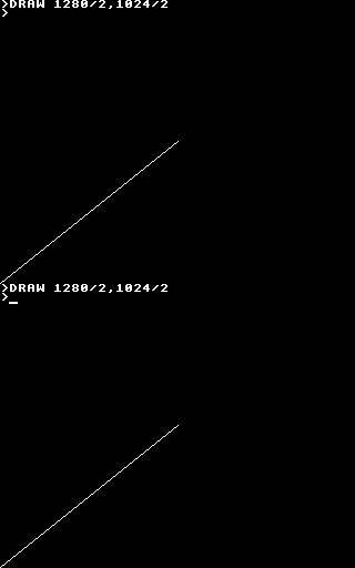
Thus far I'd been using the slightly more intuitive fixed resolution of 96×64 with (0,0) in the top-left hand corner with the Y axis pointing downwards. This means that any graphics program for the TI-83+ version appears upside down and squashed into the bottom-left corner when run on the BBC Micro.
I have worked on attempting to remedy this. 1280×1024 does not divide cleanly into 96×64, so I've used a constant scale factor of 16 on both axes resulting in a virtual resolution of 1536×1024. (Flipping the Y axis is easy enough). This means that programs drawing shapes (lines, circles, triangles, rectangles, parallelograms) will run on both BBC Micro "compatible" versions of BBC BASIC and the TI-83+ and produce roughly the same results.
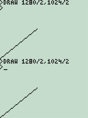
As this may not be to everyone's tastes the two options may be independently controlled with two new star commands;
- *YAXIS UP|DOWN
- *GSCALE ON|OFF
The default is to have *YAXIS UP and *GSCALE ON. To revert to the old behaviour you could specify *YAXIS DOWN and *GSCALE OFF.
I have also been working on implementing the OS call OSGBPB. This call allows you to read/write multiple bytes of data in one go, so is much faster than using the byte-at-a-time BGET# and BPUT# commands. It also provides a way to enumerate filenames, a feature I have yet to implement but one that should be useful (eg to search for data files for your own program without having the filename hard-coded or having to prompt the user).
Three sides good, four sides bad.
Sunday, 30th November 2008
Work on the TI-83+/TI-84+ port of BBC BASIC continues bit-by-bit.
I've added triangle filling (left) and, by extension, parallelogram filling (right) PLOT commands. The triangle filler is a little sluggish, tracing each edge of the triangle using 16-bit arithmetic, but it seems fairly robust. I am trying to focus on robustness over speed for the moment, but it would seem easy enough to add a special-case triangle edge tracer if both ends of the edge can fit into 8-bit coordinates (all inputs to plot commands use 16-bit coordinates).
The parallelogram on the right is specified with three coordinates, and the fourth point's position is calculated with point3-point2+point1. As parallelograms are drawn as two triangles there's an overdraw bug when they are drawn in an inverting plotting mode.

This needs to be fixed.
The BBC Micro OS exposed certain routines in the &FF80..&FFFF address range. These routines carried out a wide variety of tasks, from outputting a byte to the VDU to reading a line of input or changing the keyboard's auto-repeat rate. BBC BASIC (Z80) lets the person implementing the host interface catch these special-case calls, so I've started adding support for them. A friend very kindly donated copies of three BBC Micro books, including the advanced user guide (documenting, amongst other things, the OS routines) and the BASIC ROM manual.
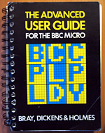 As an example, if you write the value 16 to the VDU it clears the text viewport. BBC BASIC has the CLS keyword for this, but you can also send values directly to the VDU with the VDU statement, like this: VDU 16. This in turn calls the BBC Micro's OSWRCH routine, located at &FFEE, with the accumulator A containing the value to send to the VDU. An alternative method to clear the text viewport would therefore be A%=16:CALL &FFEE.
Now, you may well be wondering how this is of any use, given the existance of a perfectly good CLS statement (or, failing that, the VDU statement). The usefulness becomes apparent when you remember that BBC BASIC has an inline assembler. There is no CLS or VDU instruction in Z80 assembly, but by providing an OSWRCH routine you can interact with the host interface and so clear the screen from an assembly code routine; in this case [LD A,16:CALL &FFEE:] (square brackets delimit assembly code).
Sadly, there is a limitiation in the TI-83+/TI-84+ hardware that prevents this from working seamlessly. The memory in the range &C000..&FFFF, where these routines reside, is mapped to RAM page 0. RAM page 0 has a form of execution protection applied to it, so if the Z80's program counter wanders onto RAM page 0 the hardware triggers a Z80 reset. To this end all of these OS calls are relocated to &4080..&40FF, so in the Z80 assembly snippet above you would CALL &40EE instead. This only applies to CALLs made from assembly code - the BASIC CALL statement traps calls to the &FF80..&FFFF so they can be redirected seamlessly to retain compatibility with other versions of BBC BASIC (Z80).
After all this work I noticed that the host interface was crashing in certain situations, especially when writing to a variable-sized file in a loop. This is the sort of bug that is tricky to fix; sometimes it would crash instantly, sometimes it would write the first 5KB of the file fine then crash.
It turned out to be a bug in the interrupt service routine (ISR). In this application the ISR is used to handle a number of tasks such as trapping the On key being pressed to set the Escape condition or to increment the TIME counter (as well as other time-related features such as the keyboard auto-repeat or cursor flash). On the TI-83+, which doesn't have a real-time clock, it also calls a RTC.Tick function approximately once per second to update the (very inaccurate) software real-time clock. To call this function it uses the BCALL OS routine. It appears that if the BCALL routine was used from an ISR when the TI-OS was in the process of enlarging a file it would crash. Removing the call to RTC.Tick appears to have fixed the bug entirely.

It is possible to put BBC BASIC into an infinite loop if you make a mistake in your error handler. In the above example program the error handler in line 10 fails to bail out on an error condition, running back into line 20 that itself triggers a division by zero error. You cannot break out of the loop by pressing On as that works by triggering an error (error 17, Escape). To improve safety I've added a feature whereby holding the On key down for about 5 seconds causes BBC BASIC to restart. This loses the program that was previously loaded in RAM, but you can retrieve with the OLD statement.
I've also rewritten all of the "star" commands. These are commands, usually prefixed with an asterisk, that are intended to be passed to the OS. As the TI-83+/TI-84+ does not have an especially useful command-line driven interface (most of the UI is menu-driven) I've implemented this part myself, basing its commands on ones provided by the BBC Micro OS. For example, *SAVE can be used to save a block of memory to a file, or *CAT (aliased to *DIR and *.) can be used to show a list of files.

In the case of *CAT I've added a pattern-matching feature that lets you use ? and * as wildcards to limit the files shown.
After noticing that *COPY took three seconds to copy an 860 byte file I optimised some of the file routines to handle block operations more efficiently. Reading and writing single bytes at a time is still rather sluggish, but I'm not sure that there's much I can really do about that.

Finally, for a bit of fun I noticed a forum post enquiring about writing assembly programs on the calculator. Here's a program that assembles a regular Ion program using BBC BASIC's assembler.
BBC BASIC's improved filling, *EXEC and Lights Out
Thursday, 13th November 2008
Progress on the TI-83+/TI-84+ port of BBC BASIC continues - I'm hoping to get a beta release out soon. ![]()


I've done quite a lot of work on the graphics features. Every shape that is plotted can be set to either the foreground colour, background colour or to invert the pixels it covers. This wasn't implemented properly (everything was always drawn in the foreground colour) which has been corrected.
The first image in the above group shows the flood-filler in action, filling inside and outside a triangle. The second image demonstrates the ellipse drawing and filling code by qarnos. It had a small amount of overdraw, which is not normally a problem, but in an inverting plot mode drawing a pixel twice causes it to reset to its original value. This ends up leaving gaps in the circle. Fortunately he was able to give me a lot of help in fixing it. ![]()
The third image demonstrates a non-standard feature I've added - being able to set your own fill patterns. The GCOL statement lets you set the foreground or background colour, and for values between black and white a dithered fill pattern is substituted instead. GCOLPAT takes a pointer to an 8×8 pixel fill pattern and subsequent fill operations will use that instead; passing FALSE (0) to GCOLPAT or setting a colour normally via GCOL reverts to the standard dither fills.
I've also done a small amount of benchmarking. There's a sample program in the TI-83+ guidebook that draws a Sierpinski triangle.

On a regular 6MHz TI-83+, the TI program takes 7 minutes and 8 seconds to run. A direct translation to BBC BASIC executes in 2 minutes and 21 seconds, and a simplified version executes in 1 minute and 56 seconds.

I'm also trying to improve the number of OS-level "star" commands. Above is a demonstration of *EXEC which reads console input from a text file. A file is opened for output using OPENOUT, some text is written into it using PRINT#, and then it it *EXECuted. This is one possible way of converting a text file into a BBC BASIC program.

Finally, I'm trying to write a game as an example program. The above screenshot shows an incomplete clone of the Lights Out game by Tiger Electronics.
TIME$ to resume work on TI-83+ BBC BASIC
Wednesday, 29th October 2008
It's been a while since I worked on the TI-83+ calculator port of BBC BASIC, and due to a relatively modular design some of the new features I'd been working on for the Z80 computer project version could be easily transferred across.
The first addition to the calculator port is the TIME$ keyword, which lets you get or set the system time.


That's all very well and good, but only the TI-84+ calculator has real-time clock hardware - the TI-83+ doesn't have any sort of accurate timekeeping to speak of. Rather than display an error when TIME$ is used I opted to use an inaccurate software-based clock. It uses the TI-83+'s timer interrupts (roughly 118Hz) to update the date and time about once a second. The clock is reset to Mon,01 Jan 2001.00:00:00 every time BBC BASIC is restarted and keeps abysmal time, but software designed to use the clock will at least run.
I have been transferring and amending documentation from Richard Russell's website to a private installation of MediaWiki. There are about 120 entries so far; having documentation puts me much closer to being able to make a release.
I have also fixed a handful of bugs. One that had me tearing my hair out was something like this:
  250 DEF PROC_someproc(a,b)
  260 a=a*PI
  270 ENDPROC
The program kept displaying a No such variable error on line 260. Well, a is clearly defined, and retyping the procedure in another program worked, so what was the problem here? I thought that maybe one of the graphics calls or similar was corrupting some important memory or modifying a register it shouldn't. It turns out that the problem lay in the Windows-based tokeniser - it was not picking up PI as a token, for starters, and was storing the ASCII string "PI" instead. On top of that, it was treating anything after a * as a star command, which aren't tokenised either. (Star commands, such as *REFRESH, are passed directly to the host interface or OS). Retyping the problematic lines caused BBC BASIC to retokenise them, which was why I couldn't replicate the problem in other programs. By fixing the tokeniser, everything started working again.
The source code for the analogue clock program is listed below.
   10 *REFRESH OFF
   20 VDU 29,48;32;
   30 GCOL 0,128
   40 REPEAT
   50   t$=TIME$
   60   hour%=VAL(MID$(t$,17,2))MOD12
   70   min%=VAL(MID$(t$,20,2))
   80   sec%=VAL(MID$(t$,23,2))
   90   sec=sec%/60
  100   min=(min%+sec)/60
  110   hour=(hour%+min)/12
  120   CLG
  130   GCOL 0,127
  140   MOVE 0,0
  150   PLOT 153,31,0
  160   GCOL 0,0
  170   FOR h=1TO12
  180     hA= h/6*PI
  190     hX=30*SIN(hA)
  200     hY=30*COS(hA)
  210     MOVE hX,hY
  220     DRAW hX*0.9,hY*0.9
  230   NEXT h
  240   PROC_drawHand(sec,30)
  250   PROC_drawHand(min,24)
  260   PROC_drawHand(hour,16)
  270   *REFRESH
  280 UNTIL INKEY(0)<>-1
  290 *REFRESH ON
  300 END
  310 DEF PROC_drawHand(pos,length)
  320 MOVE 0,0
  330 pos=pos*2*PI
  340 DRAW length*SIN(pos),-length*COS(pos)
  350 ENDPROC
I translated the tokeniser source code to PHP so that by pointing a browser to file.bbcs for a known file.bbc the highlighted, detokenised source code is served as HTML instead. Hurrah for mod_rewrite, and if you're using IIS Ionic's Isapi Rewrite Filter performs a similar job using the same syntax.
Graphical text, BASIC tokeniser and flood-filling
Tuesday, 29th July 2008
I've got a fairly hackish "graphical text" mode set up (enabled with VDU 5, disabled with VDU 4) that causes all text that is sent to the console to be drawn using the current graphics mode (at the graphics cursor position, using the graphics colour and logical plotting mode and graphics viewport). This allows text to be drawn at any position on-screen, but is (understandably) a bit slower and doesn't let you do some of the things you may be used to (such as scrolling text, copy-key editing and the like).

I've also done some work on a tool to convert files from the PC to use in BBC BASIC. It takes the form of a Notepad-like text editor:
BBC BASIC programs are stored in a tokenised format (usually .bbc files on a PC) and need to be wrapped into a .8xp for transferring to the calculator. The editor above can open .8xp, .bbc and .txt directly, and will save to .8xp.
The detokeniser can be passed a number of settings, which can be used to (for example) generate HTML output, like this. The indentation is generated by the detokeniser (leading/trailing whitespace is stripped by the tokeniser). The tool can also be used to directly convert binaries into .8xp files if need be.


I've been doing a little work on a flood-filling algorithm. (PLOT 128-135, 136-143). The above images show its progress; on the left is the first version (which can only fill in black). There is a hole in the bottom-left of the shape, so the leaking is intentional. It also stops one pixel away from the screen boundary -- this too is intentional (it clips against the viewport). The second version, in the middle, plugs the leak and applies a pattern (which will be a dither pattern in BBC BASIC) to the filled area. On the right is the third version, which will fill over black or white pixels with a pattern.
The main filling algorithm needs a 764 byte buffer for the node queue and three 16-bit pointer variables to manage the queue. I've rounded the queue size up to 768 bytes, so it fits neatly on one of the RAM areas designed to store a bitmap of the display.
The problem is filling with a pattern. The way I currently do this is to back up the current screen image to a second 768-byte buffer, fill in black as normal, then compare the two buffers to work out which bits have been filled and use those as a mask to overlay the dither pattern. This is quite a lot of RAM, just to flood-fill an image!
For those who are interested, I'm using the "practical" implementation of a flood fill algorithm from Wikipedia.
Text viewports and sprites
Monday, 21st July 2008
Back to work on the TI-83 Plus port of BBC BASIC! To complement the graphics viewport I've added support for text viewports — this lets you define the area the text console uses. The following VDU commands are now supported:
- VDU 24,<left>;<top>;<right>;<bottom>;
Define a graphics viewport. - VDU 28,<left>,<top>,<right>,<bottom>
Define a text viewport. - VDU 26
Reset both viewports to their default settings (full screen). - VDU 29,<x>;<y>;
Defines the graphics origin.

The above screenshots defines the graphics viewport to fill the left hand side of the screen and shunts the text viewport over to the right half, using the following code:
VDU 24,0;0;47;63;
VDU 28,12,0,23,9
VDU 29,24;32;
I've also added simple sprite drawing to BBC BASIC's PLOT command. PLOT usually takes a shape type and two coordinates, but for sprites (shapes 208..215) I've added an extra parameter - the address of the sprite data to use.

   10 DIM ball 7
   20 ball?0=&3C
   30 ball?1=&5E
   40 ball?2=&8F
   50 ball?3=&DF
   60 ball?4=&FF
   70 ball?5=&FF
   80 ball?6=&7E
   90 ball?7=&3C
  100 *REFRESH OFF
  110 REPEAT
  120   CLG
  130   T=TIME/100
  140   FOR P=0 TO 5
  150     A=P/3*PI+T
  160     X=16*SIN(A)+44
  170     Y=16*COS(A)+28
  180     PLOT 213,X,Y,ball
  190   NEXT
  200   *REFRESH
  210 UNTIL INKEY(0)<>-1
  220 *REFRESH ON
The above code allocates 8 bytes of memory (DIM ball 7) then copies the sprite data to it by use of the ? indirection operator. This is a little laborious, so in reality you'd probably store your sprites in a binary file external to the main program, and might load them like this:
   10 ball%=FN_loadSprite("SPRITES",0)
   20 face%=FN_loadSprite("SPRITES",1)
   30 *REFRESH OFF
   40 REPEAT
   50   CLG
   60   T=TIME/100
   70   FOR P=0 TO 5
   80     A=P/3*PI+T
   90     X=16*SIN(A)+44
  100     Y=16*COS(A)+28
  110     PLOT 213,X,Y,ball%
  120   NEXT
  130   PLOT 213,44,28,face%
  140   *REFRESH
  150 UNTIL INKEY(0)<>-1
  160 *REFRESH ON
  170 END
  180 DEF FN_loadSprite(f$,i%)
  190 fh%=OPENIN(f$)
  200 PTR#fh%=i%*8
  210 DIM spr 7
  220 FOR j%=0 TO 7
  230   spr?j%=BGET#fh%
  240 NEXT j%
  250 CLOSE#fh%
  260 =spr
  270 ENDPROC
(Note FN_loadSprite() at the end of the program). The result is the following:

Next up: drawing text at the graphics cursor position (as sprites).
Clipped graphics and ellipses
Monday, 23rd June 2008
qarnos — author of the superb Aether 3D engine — has been lending a hand with the BBC BASIC graphics API and contributed a large amount of very useful code.

First up is some code to clip 16-bit line coordinates down to 8-bit coordinates. This allows for lines to be partially (or completely) off the screen.


He's also written a fast ellipse drawing and filling routine. The ellipses are also clipped to the viewport and are filled with an 8×8 pixel pattern.

The graphics viewport can be redefined using the VDU 24,left;top;right;bottom; command as demonstrated in the above example.


GCOL can also be used to set a plotting mode; either plotting the specified colour directly, performing a logical operation (OR, AND, EOR) or inverting the existing colour.

All but the last of the above screenshots are the result of running BBC BASIC on a TI-83+ SE at 15MHz. The final screenshot is running at the regular 6MHz.
Gyrating cubes in BBC BASIC
Thursday, 12th June 2008
Work has been keeping me busy recently, but I've tried to set aside a small amount of time each evening to reclaim some sanity and do a little work on BBC BASIC. Not much progress has been made, but there has been some at least.


On the left is the program running on an 83+ SE at 15MHz, on the right on the regular 83+ at 6MHz. If you really wanted to do 3D in BBC BASIC you could probably get away with writing some of the more expensive operations — such as transforming/projecting vertices in batches — in assembly, but that would sort of go against the whole point of trying to write a program to test the speed of BASIC. ![]()
Here's the rather naïve code:
   10 *REFRESH OFF
   20 DIM p%(15)
   30 fps%=0
   40 lfps%=0
   50 fpst%=TIME+100
   60 REPEAT
   70   rX=TIME/300
   80   rY=TIME/400
   90   SrX=SIN(rX)
  100   CrX=COS(rX)
  110   SrY=SIN(rY)
  120   CrY=COS(rY)
  130   pt%=0
  140   FOR x=-1TO1STEP2
  150     FOR y=-1TO1STEP2
  160       FOR z=-1TO1STEP2
  170         tX=y*CrX-x*SrX
  180         tY=-x*CrX*SrY-y*SrX*SrY-z*CrY
  190         tZ=3-x*CrX*CrY-y*SrX*CrY+z*SrY
  200         p%(pt%)=tX*40/tZ+48
  210         pt%=pt%+1
  220         p%(pt%)=tY*40/tZ+32
  230         pt%=pt%+1
  240       NEXT
  250     NEXT
  260   NEXT
  270   CLG
  280   PRINTTAB(10,0)lfps%" FPS"
  290   MOVE p%(0),p%(1)
  300   DRAW p%(4),p%(5)
  310   DRAW p%(12),p%(13)
  320   DRAW p%(8),p%(9)
  330   DRAW p%(0),p%(1)
  340   DRAW p%(2),p%(3)
  350   DRAW p%(6),p%(7)
  360   DRAW p%(14),p%(15)
  370   DRAW p%(10),p%(11)
  380   DRAW p%(2),p%(3)
  390   MOVE p%(4),p%(5)
  400   DRAW p%(6),p%(7)
  410   MOVE p%(12),p%(13)
  420   DRAW p%(14),p%(15)
  430   MOVE p%(8),p%(9)
  440   DRAW p%(10),p%(11)
  450   *REFRESH
  460   fps%=fps%+1
  470   IF TIME>fpst% THEN lfps%=fps%:fps%=0:fpst%=TIME+100
  480 UNTIL INKEY(0)<>-1
  490 *REFRESH ON
  500 END
I have also added support for the COLOUR statement (for changing the text foreground and background colour) and copy key editing.


Copy key editing, as demonstrated in the screenshot on the right, lets you break the text input cursor into two parts - a write cursor (which is left behind on the line you were editing) and a read cursor, which can be positioned anywhere on the screen. Pressing the copy key (in this case, XTθn) reads a character under the read cursor and writes it to the write cursor, then increments both.
One feature that's a bit more fun is the support of device files. This is a way of accessing external devices as if they were files. For example, by opening the file AT.DEV you can read and write bytes using the AT protocol (used by AT and PS/2 keyboards and mice) using BBC BASIC's built-in file manipulation routines.

You could use this to do something useful, or could just use this to flash the LED on a keyboard back and forth.
   10 keyb%=OPENOUT"AT.DEV"
   20 DATA 2,4,1,4,-1 : REM LED flash pattern (-1 terminated).
   30 REPEAT
   40   READ l%
   50   REPEAT
   60     PROC_setled(l%)
   70     PROC_pause(30)
   80     READ l%
   90   UNTIL l%=-1
  100   RESTORE
  110 UNTIL FALSE
  120 END
  130 :
  140 DEF PROC_flushin
  150 REPEAT
  160   IF EXT#keyb% d%=BGET#keyb%
  170 UNTIL NOT EXT#keyb%
  180 ENDPROC
  190 :
  200 DEF PROC_setled(l%)
  210 BPUT#keyb%,&ED
  220 PROC_flushin
  230 BPUT#keyb%,l%
  240 PROC_flushin
  250 ENDPROC
  260 :
  270 DEF PROC_pause(t%)
  280 start%=TIME
  290 REPEAT UNTIL TIME >= start%+t%
  300 ENDPROC
BBC BASIC running as an application
Tuesday, 3rd June 2008
Richard Russell has kindly supplied the project with the BBC BASIC relocatable modules — compiled object files which can be relocated to any memory address by a linker — which means that BBC BASIC can now be configured to run on the TI's hardware.
The tools to relocate the modules run under CP/M, which means that rather trying to integrate the relocation into the build process (which would be a little awkward) I'm going to relocate the modules to a fixed base address and inject the resulting binary file directly into the application.
BBC BASIC will reside from &4100. From &4000..&40FF is a jump table, which BASIC uses to interact with the host. As the addresses of the host interface entry points will change as the code changes, and I don't wish to keep on relinking BASIC in CP/M, a fixed jump table makes life a lot easier. BASIC jumps to a predetermined fixed address in the jump table, which redirects - via a second jump - to the real entry point.


I think I've implemented all of the main host interface entry points, though some — notably those involved in file I/O — need making more robust. I don't currently reserve any memory for BASIC's scratch area, which means that the TI-OS can (and does) decide to overwrite it at inconvenient moments. Even though TI provided us with at least three different 768-byte buffers (the exact size of BBC BASIC's scratch area), none of them are aligned to a 256 byte boundary. ![]()
BBC BASIC
Monday, 19th May 2008
This is a project I initially attempted to get off the ground about four years ago, but never did. Anyhow, I've started work on it, and thanks to help from Richard Russell (the original developer) and J.G.Harston (who comparatively recently developed the Sinclair ZX Spectrum port) it looks like it should be possible this time around. ![]()
BBC BASIC was the native programming language on Acorn's BBC Micro. It's a structured BASIC dialect and supports procedures and functions, permitting far nicer code than the line-numbered GOTO and GOSUB code on other contemporary machines. It also has a built-in assembler, for inline assembly.
There is no source available, which is where the problems start to come in. Fortunately, J.G.Harston has developed a utility that permits the platform-agnostic BBC BASIC interpreter to be relocated. However, it assumes that the system has a jump table in RAM from $FF80..$FFFF (this jump table would be used to call platform-specific code); this memory range is not executable on the TI-83+. Execution protection in the $C000..$FFFF range may also cause issues for inline assembly code (which is, naturally, executed from RAM).
The TI-OS does not offer an especially suitable environment for BBC BASIC either; it is mainly menu driven (a command-line driven environment is preferable), does not have a plain text editor and does not use ASCII. To resolve this issues, I've concentrated on developing a suitable environment for BBC BASIC to live in, including a command-line interface and text editor.

Text files are stored as AppVars with a TEXTFILE header, and I've developed a Windows-based notepad clone for editing them (it saves and loads directly to and from .8xv). The following commands are currently supported (see here for a reference from the Windows verion): BYE, COPY, DELETE, DIR, ERASE, EXEC, QUIT, RENAME, TYPE, |.
To enter the editor, EDIT can be used. This presents a full-screen editor a little like the TI-OS program editor, but edits plain text files.
The interface transparently supports AT keyboards (which are rather easier to type on than the TI's keypad). The character resolution is 24 columns in 10 rows (4x6 pixel characters), giving you quite a lot of room to see what you're working on.
I intend on the final program being a 2-page Flash application; one page for BBC BASIC, and one page for the environment and OS interface. This unfortunately makes this a TI-83+ only project.
Even if I don't manage to shoe-horn BBC BASIC onto the TI-83+, the interface code (which uses direct hardware access for everything but opening and editing AppVars) could be useful for other projects.
Emulating TI-OS 1.15 and a greyscale LCD
Monday, 29th October 2007
OS 1.15 appears to boot, and if I run an OS in Pindur TI, archive the files (copy them to Flash ROM) then use that ROM dump in my emulator the files are still there, where they can be copied to RAM.
Trying to re-archive them results in a fairly un-helpful message, as I haven't implemented any Flash ROM emulation (nor can I find any information on it)...
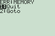
Applications (which are only ever stored and executed on Flash ROM) work well, though.

I've also updated the LCD emulation a little to simulate the LCD delay; greyscale programs (that flicker pixels on and off) work pretty well now.


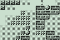

Brass 3 and TI-83+ Emulation
Friday, 26th October 2007
Brass 3 development continues; the latest documentation (automatically generated from plugins marked with attributes via reflection) is here. The compiler is becoming increasibly powerful - and labels can now directly store string values, resulting in things like an eval() function for powerful macros (see also clearpage for an example where a single function is passed two strings of assembly source and it uses the smallest one when compiled).
Thanks to a series of hints posted by CoBB and Jim e I rewrote my TI-83+ emulator (using the SMS emulator's Z80 library) and it now boots and runs pretty well. The Flash ROM archive isn't implemented, so I'm stuck with OS 1.12 for the moment (later versions I've dumped lock up at "Defragmenting..."). I also haven't implemented software linking, and so to transfer files I need to plug in my real calculator to the parallel port and send files manually.
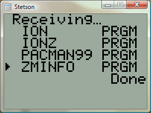
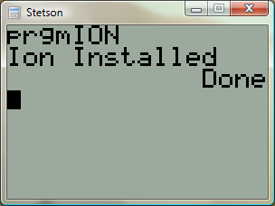
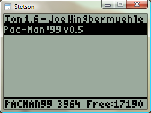
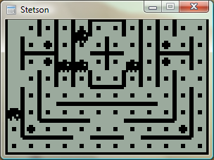
8-bit Raycasting Quake Skies and Animated Textures
Monday, 20th August 2007
All of this Quake and XNA 3D stuff has given me a few ideas for calculator (TI-83) 3D.
One of my problems with calculator 3D apps is that I have never managed to even get a raycaster working. Raycasters aren't exactly very tricky things to write.
So, to help me, I wrote a raycaster in C#, limiting myself to the constraints of the calculator engine - 96×64 display, 256 whole angles in a full revolution, 16×16 map, that sort of thing. This was easy as I had floating-point maths to fall back on.
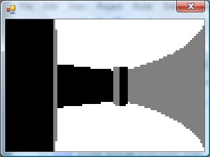
With that done, I went and ripped out all of the floating-point code and replaced it with fixed-point integer arithmetic; I'm using 16-bit values, 8 bits for the whole part and 8 bits for the fractional part.
From here, I just rewrote all of my C# code in Z80 assembly, chucking in debugging code all the way through so that I could watch the state of values and compare them with the results from my C# code.

The result is rather slow, but on the plus side the code is clean and simple. ![]() The screen is cropped for three reasons: it's faster to only render 64 columns (naturally), you get some space to put a HUD and - most importantly - it limits the FOV to 90°, as the classic fisheye distortion becomes a more obvious problem above this.
The screen is cropped for three reasons: it's faster to only render 64 columns (naturally), you get some space to put a HUD and - most importantly - it limits the FOV to 90°, as the classic fisheye distortion becomes a more obvious problem above this.
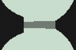
I sneaked a look at the source code of Gemini, an advanced raycaster featuring textured walls, objects and doors. It is much, much faster than my engine, even though it does a lot more!
It appears that the basic raycasting algorithm is pretty much identical to the one I use, but gets away with 8-bit fixed point values. 8-bit operations can be done significantly faster than 16-bit ones on the Z80, especially multiplications and divisions (which need to be implemented in software). You can also keep track of more variables in registers, and restricting the number of memory reads and writes can shave off some precious cycles.
Some ideas that I've had for the raycaster, that I'd like to try and implement:
- Variable height floors and ceilings. Each block in the world is given a floor and ceiling height. When the ray intersects the boundary, the camera height is subtracted from these values, they are divided by the length of the ray (for projection) and the visible section of the wall is drawn. Two counters would keep track of the upper and lower values currently drawn to to keep track of the last block's extent (for occlusion) and floor/ceiling colours could be filled between blocks.
- No texturing: wall faces and floors/ceilings would be assigned dithered shades of grey. I think this, combined with lighting effects (flickering, shading), would look better than monochrome texture mapping - and would be faster!
- Ray-transforming blocks. For example, you could have two 16×16 maps with a tunnel: the tunnel would contain a special block that would, when hit, tell the raycaster to start scanning through a different level. This could be used to stitch together large worlds from small maps (16×16 is a good value as it lets you reduce level pointers to 8-bit values).
- Adjusting floors and ceilings for lifts or crushing ceilings.
As far as the Quake project, I've made a little progress. I've added skybox support for Quake 2:
Quake 2's skyboxes are simply made up of six textures (top, bottom, front, back, left, right). Quake doesn't use a skybox. Firstly, you have two parts of the texture - one half is the sky background, and the other half is a cloud overlay (both layers scroll at different speeds). Secondly, it is warped in a rather interesting fashion - rather like a squashed sphere, reflected in the horizon:
For the moment, I'm just using the Quake 2 box plus a simple pixel shader to mix the two halves of the sky texture.
I daresay something could be worked out to simulate the warping.
The above is from GLQuake, which doesn't really look very convincing at all.
I've reimplemented the texture animation system in the new BSP renderer, including support for Quake 2's animation system (which is much simpler than Quake 1's - rather than have magic texture names, all textures contain the name of the next frame in their animation cycle).
VMusic2 - USB for the 83+
Monday, 21st May 2007
The TI-83+ lacks something the 84+ series has - a USB port.
Enter the VMusic2. This low-cost (£25) module offers a USB host controller with a simple serial interface that can be used to read/write FAT-formatted USB mass storage devices. It can also play MP3 files straight from the drive!
This is all very well, but the TI doesn't have a standard serial port either. To handle communications between the two, therefore, is a PICAXE-28X1 microcontroller.
The TI can then run a program that communicates using its standard linking protocol.
I've posted a thread on MaxCoderz with more information about the project. For those interested in the VMusic2 device, here's a datasheet and here are the commands.
Yes, I know I should probably get a life. I blame the solder fumes.
SonyIR
Monday, 30th April 2007
I take a strange enjoyment in reading format and protocol documentation, and I find it to be one of the most rewarding tasks. Hence the Sega emulator project, the DOOM project, the Vgm2Midi project and so on.
This project is more hardware related - it's an infrared remote control library for the TI-83 series calculators. It supports the SIRCS (Sony) protocol, with command words of 12, 15 and 20 bits.
Video of the library in action (960KB WMV).
The hardware is very simple if you just want to transmit, and a single-package infrared receiver/amplifier/demodulator makes the receiving circuit not that much more complex.
The library also comes with a program that can be used to turn an 83+ into a programmable remote control. It supports multiple device profiles, and editing is easy - press the key (on the calculator) you wish to customise, point your remote at the receiver and press the button you want change to and the details are automatically saved.


TI Emulation, Functions in Brass and Gemini on the Sega Game Gear
Tuesday, 13th February 2007
This post got me wondering about a TI emulator. I'd rather finish the SMS one first, but so as to provide some pictures for this journal I wrote a T6A04 emulator (to you and me, that's the LCD display driver chip in the TI-82/83 series calculators). In all, it's less than a hundred lines of code.
The problem with TI emulation is that one needs to emulate the TIOS to be able to do anything meaningful. Alas, I had zero documentation on the memory layout of the TI calculators, and couldn't really shoe-horn the ROM dump into a 64KB RAM, so left it out entirely. That limits my options as to what I can show, but here's my Microhertz demo -

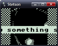
I've added native support for functions in Brass.
The old Brass could do some function-type things using directives; for example, compare the two source files here:
.fopen fhnd, "test.txt"          ; Opens 'test.txt' and stores a handle in fhnd
.fsize fhnd, test_size           ; Stores the size of the file in test_size

.for i, 1, test_size
    .fread fhnd, chr             ; Read a byte and store it as "chr"
    .if chr >= 'a' && chr <= 'z' ; Is it a lowercase character?
        .db chr + 'A' - 'a'
    .else
        .db chr
    .endif
.loop

.fclose fhnd                      ; Close our file handle.
I personally find that rather messy. Here's the new version, using a variety of functions from the 'File Operations' plugin I've been writing:
fhnd = fopen("test.txt", r)

#while !feof(fhnd)
    chr = freadbyte(fhnd)
    .if chr >= 'a' && data <= 'z'
        .db chr + 'A' - 'a'
    .else
        .db chr
    .endif
#loop

fclose(fhnd)
I find that a lot more readable.
An extreme example is the generation of trig tables. Brass 1 uses a series of directives to try and make this easier.
.dbsin angles_in_circle, amplitude_of_wave, start_angle, end_angle, angle_step, DC_offset
Remembering that is not exactly what I'd call easy. If you saw the line of code:
.dbsin 256, 127, 0, 63, 1, 32
...what would you think it did? You'd have to consult the manual, something I'm strongly opposed to. However, this code, which compiles under Brass 2, should be much clearer:
#for theta = 0, theta < 360, ++theta
    .db min(127, round(128 * sin(deg2rad(theta))))
#loop
By registering new plugins at runtime, you can construct an elaborate pair of directives - in this case .function and .endfunction - to allow users to declare their own.
_PutS = $450A

.function bcall(label)
    rst $28
    .dw label
.endfunction

bcall(_PutS)
You can return values the BASIC way;
.function slow_mul(op1, op2)
    slow_mul = 0
    .rept abs(op1)
        .if sign(op1) == 1
            slow_mul += op2
        .else
            slow_mul -= op2
        .endif
    .loop
.endfunction

.echo slow_mul(log(100, 10), slow_mul(5, 4))
I had a thought (as you do) that it would be interesting to see how well a TI game would run on the Sega Master System. After all, they share the CPU, albeit at ~3.5MHz on the SMS.
However, there are some other differences...
- Completely different video hardware.
- Completely different input hardware.
- 8KB RAM rather than 32KB RAM.
- No TIOS.
The first problem was the easiest to conquer. The SMS has a background layer, broken up into 8×8 tiles. If I wrote a 12×8 pattern of tiles onto the SMS background layer, and modified the tile data in my own implementation of _grBufCpy routine, I could simulate the TI's bitmapped LCD display (programs using direct LCD control would not be possible).
You can only dump so much data to the VRAM during the active display - it is much safer to only write to the VRAM outside of the active display period. I can give myself a lot more of this by switching off the display above and below the small 96×64 window I'll be rendering to; it's enough to perform two blocks, the left half of the display in one frame, the right in the next.
As for the input, that's not so bad. Writing my own _getK which returned TI-like codes for the 6 SMS buttons (Up, Down, Left, Right, 1 and 2) was fine, but games that used direct input were a bit stuck. I resolved this by writing an Out1 and In1 function that has to be called and simulates the TI keypad hardware, mapping Up/Down/Left/Right/2nd/Alpha to Up/Down/Left/Right/1/2.
The RAM issue can't be resolved easily. Copying some chunks of code to RAM (for self-modifying reasons) was necessary in some cases. As for the lack of the TIOS, there's no option but to write my own implementation of missing functions or dummy functions that don't do anything.
Even with the above, it's still not perfect. If I leave the object code in Gemini, the graphics are corrupted after a couple of seconds of play. I think the stack is overwriting some of the code I've copied to RAM.
No enemies make it a pretty bad 'game', but I thought it was an entertaining experiment.
Internal PS/2 Port
Friday, 6th October 2006
What's that in the bottom left hand corner?
Kerm Martian has added a PS/2 port to his calculator (click the picture for better pictures and the original thread). He has been developing a shell, entitled DoorsCS (click for website) which sports an impressive set of GUI controls - hence the mouse!
Emerson Beta 2
Friday, 22nd September 2006
Sorry about the lack of updates, but I have been incredibly busy with work related programming.
One small project I've had a chance to update is Emerson - my keyboard and mouse library for the TI-83 series calculator.
I know, I can't type layout. ![]() Download the library (and demo) here.
Download the library (and demo) here.
Multithreading on the TI-83 Plus
Thursday, 3rd August 2006
I'm not really clued up on the way these new-fangled modern operating systems handle running multiple threads, so I apologise in advance if this isn't really proper multithreading.
Basically, I was pondering (as one does) whether it would be possible to run any number of threads on the TI-83 Plus. I daresay others have done this in the past, but not having access to the internet at the time to check I thought I'd do my own bit of experimentation.
The way I can see this working is to give each thread a small amount of time to run in (time slice). At the end of one thread running, I would save the calculator's state away, and load the state for the next thread. I would keep on swapping threads several times a second, giving each their own bit of time and preserving their state.
What I really needed to know was what needed to be preserved between executions. Really, there isn't a lot - just the registers. PC and SP clearly need to be preserved, so that when a thread is resumed it resumes running at the point it was left at. Keeping the other general-purpose registers (AF, BC, DE, HL, IX, IY) safe would be important as well.
Naturally, I'll need to also preserve the stack. Or rather, for each thread, I'll need to allocate some memory for a stack and point the new thread's SP register at the end of that new memory. To keep things simple, I'll just point my test thread's SP at $FFFF-200, as the TI is arranged to have 400 bytes of stack RAM, growing backwards from $FFFF.
To perform the swapping, I'll use a custom interrupt (run in IM 2). The timer hardware will trigger this interrupt many times a second, so it is ideal. At the end of my custom interrupt, I'll jump into the default handler provided by the TIOS so the TIOS functions that rely on it behave correctly.
The way I see it working is like this:
Pop value off stack. This will be the program counter of the last running thread. (->A)
Save current stack pointer. (->B)
Set stack pointer to area in RAM where I can preserve registers for this thread. (<-C)
Push IY, IX, HL, DE, BC, AF to the stack.
Push old stack pointer (<-B) to stack.
Push old program counter (<-A) to stack.
Find the address of the RAM where we have stored the registers for the next thread.
Load it into the stack pointer.
Pop value off stack, store it (will be PC) (->D)
Pop value off stack, store it (will be SP) (->E)
Pop AF, BC, DE, HL, IX, IY off stack.
Save current stack pointer (end of RAM area used to store registers for new thread) as address of last thread for next interrupt. (->C).
Load value into SP (<-E)
Push new thead's PC to stack (<-D)
Jump into TIOS interrupt handler ->
Effectively, all this does is take the pointer stored when the current thread was resumed, dump all the registers into the memory it points to, hunts the next thread, reloads the registers and saves the pointer for next interrupt.
Does it work?

The above screenshot doesn't look too impressive, I'll give you that. There are only two threads running. The secondary thread is drawing all those random dots on the LCD. The other thread (which is the main program thread) just contains "bcall(_getkey)" - hence the 2nd/Alpha icons appearing,
I'll make the primary thread do something a bit more exotic - display random characters on the left side of the screen, the secondary work on the right side of the screen:

The code for this is simply:
Main
	.include "Multithread/Multithread.asm"


	; Kick things into action.
	call Multithread.Init

	; For the moment, the secondary thread is hard-coded, and
	; the 'multithreading' code ONLY switches back and forth between
	; two hard-coded thread slots.
-

	halt ; Slow things down a bit here.

	ld b,8
	call ionRandom
	ld (curCol),a

	ld b,8
	call ionRandom
	ld (curRow),a

	ld b,0
	call ionRandom
	bcall(_PutMap)
	bcall(_getCSC)
	cp skClear
	jr nz,{-}

	call Multithread.End
	ret

; ---------------------------------------------------------

SecondaryThread

	di ; Don't want any other thread writing to the LCD!

	ld b,64
	call ionRandom
	add a,$80
	push af ; Save for later...
		out ($10),a

		ld b,48
		call ionRandom
		add a,48
		ld b,a
		srl a
		srl a
		srl a
		add a,$20
		out ($10),a

		ld a,b
		and 7
		ld c,%10000000
		jr z,{+}
		ld b,a
	-	srl c
		djnz {-}
	+

		in a,($11)
		call LcdBusy
		in a,($11)
		xor c
		ld c,a

		call LcdBusy

	pop af
	out ($10),a

	call LcdBusy
	ld a,c
	out ($11),a

	ei

	jr SecondaryThread

LcdBusy
	push af
	inc hl
	dec hl
	pop af
	ret
As you can see, there are two discrete threads running there.
Well, that's two threads up and running. What's needed to extend this to any number of threads?
- Thread management. Basically, the ability to add/remove threads at will, and have the handler be able to switch between as many threads as required.
- Allocation of new stack space. New threads will need more stack space, so I shall need to add some mechanism to steadily allocate it.
- Idle threads. One big problem is that as you add threads, each one gets progressively slower. If threads flag themselves as idle, they can be skipped so threads that do need CPU time get it. The easiest way to do this is to set a "sleep" counter which is checked when threads are switched around - if it's zero (when it runs out), the thread is given some time to run.
Off the top of my head, that's about it. There are some issues I have come across when working with this:
- TIOS routines are not thread-safe. This speaks for itself, pretty much - if you have two threads, both of which are calling bcall(_putC) to display a character, they interfere with eachother (for example - incorrectly setting the value of curCol or curRow as one thread changes it as the other one is reading it) which causes crashes.
- Variables can become an issue. Same reason as above - if two threads call a function which uses a set RAM location for a local variable, the variable can be changed half way through.
One possible way to get around thread-unsafety of functions is to disable interrupts before calling them and reenabling them afterwards, which prevents the thread switcher from swapping them. It's a pretty lousy workaround, though. ![]()
Map Editing
Wednesday, 26th July 2006
I added five-level grey:
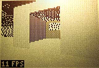
The greyscale effect is optional (adds about 8 lines of code, only runs once per frame and can be disabled with a single switch in the engine package's Settings.inc file.

Anyway, I've started throwing together a very primitive level editor. (GDI+)
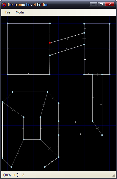
Insert inserts a new vertex at the mouse location; delete removes the closest vertex. Point at a vertex, hold W, move to another vertex and release W to insert a new wall. (Single-sided, hold shift at the same time to add a double-sided wall). Use D to remove walls in the same way. That sort of thing.
The two different types of wall are represented with white lines (single-sided) and grey lines (double-sided). There are therefore 9 different sectors in the above image.
Imagine that the walls have been kept simple (fixed floor/ceiling heights, single segment) and can have one of 6 different 'colours' - from 0 (invisible/transparent) to 1 (white) through to 3 (50% grey) and finally 5 (black).
Therefore, for the sake of simplicity, assume that all of the double-sided grey walls in the above screenshot are invisible. The room in the south-west of the screenshot is an octogonal room with a doorway in the eastern wall and a square pillar in the middle.
The four double-sided walls in this south-western room are not redundant. You will notice that the level has been cut up into convex sectors. This has one small advantage - it reduces the number of walls that will need to be sorted, as I only need to sort entire sectors for occlusion purposes.
Also, I can see that I can get some sort of portal*-based system up and running. Suppose I use the editor to create this:
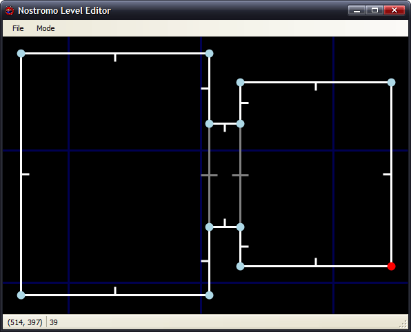
If I was to start in the left sector, I would go through and draw each wall. I'd hit the double-sided wall at some point, and know that after this sector I'd have to move into the sector in the middle. After that sector, I'd know that I'd have to move to the sector to the right. With me so far?
Let's do something radical and make that central sector a door, and close it (move the ceiling height down to meet the floor height). This time, when I move through the sectors, I'll hit this sector and see that it's closed. No matter, say I - rather than carry on walking through the sectors, I stop at that point.
By liberally sprinkling a world with doors, and keeping them shut most of the time, you can cut out a fair chunk of geometry. :)
I cannot think of the best way to handle sorting. I don't think I can just use the order in which I wander through the sectors - imagine this:
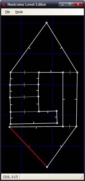
Imagine you're in the north 'triangle' and looking south. As you can see, you need to travel through more sectors to get to the larger rectangular room than the south triangular room - and using that for sorting is just wrong.
One potential workaround I can think of is that each sector has a visibility list - a list of in which order sectors appear (in front->back order - else we wouldn't be able to take advantage of portals). Problems; MASSIVE amount of data that grows exponentially with each added sector! From what I can also tell, that also seems a precomputed BSP list, done per sector (rather than work out which side of the split to follow each branch, it's already calculated for us). On the other side, this can also be used to calculate (through some nifty ray/plane intersection algorithm) which sectors will NEVER be visible from a particular sector... Hmm. I'm not afraid of 'wasting' RAM with gigantic tables - if we assume a smallish, plain level of 50 sectors, each sector would need a list of at most 49 other sectors. 49*50*2=4900B - not actually too bad. :
(Bah) Just realised that would not work (precomputed sorting based on sectors) at all.
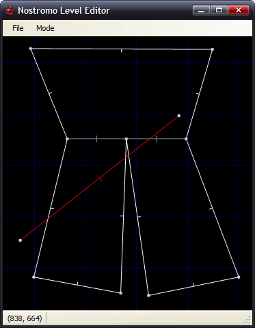
Let's say the red line is your 'view' (not a wall, quick and dirty diagram). It intersects the front of two walls, so it appears that the sort should go north->east->west sectors. However, imagine I move to the other side of the sector and look the same way (mirror the diagram, basically). Now the order goes north->west->east, and I'm still in the same sector :( Do I just clump all the sectors together and sort them all together based on the distance to the central (average) coordinate of each and the camera? (Not fast!)
Thoughts?
*I hope that's the correct word.
Coloured walls and FPS counters
Monday, 17th July 2006
I fixed most of the wall filling code. It now fills by scanline (so is considerably faster), which gives me more flexibility over what I can do with it.
For the moment, I have sacrificed speed with a routine that can handle three different fills - black, white, or 50% dithered. The routine will always blank the wall, mask out the pattern you wish to fill then OR it - which works nicely, but wastes time if you are filling plain black or white walls.
The result is quite pleasing:

As you can also see, I added scrolling skies.
The dithered walls look a bit nicer on hardware. The option to switch the initial dither pattern on alternate frames (resulting in a pseudo-greyscale) can be switched on or off, as it looks rather bad in emulators.
There is one horrible problem with the physical LCD, though - it really cannot cope with columns of alternating pixels. Compare the two shots, one being much closer to the wall (and so having more columns of alternating pixels):
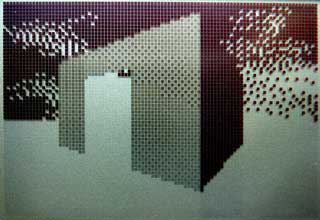
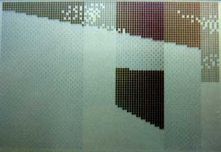
Not so good. Hopefully the world in-game will have enough content to break up the columns, but I'll have to wait and see on that count.
One major concern I've had is keeping the speed of the engine constant. Just moving the player X units per frame is not an option, as the framerate can vary wildly. I need some sort of timing!
Luckily, the calculator has fairly limited timing hardware built-in. I can use this timer via interrupts. There are various pieces of hardware that can trigger interrupts - including the On key, activity on the link IO port (any line held low will trigger an interrupt) or this timer. The TIOS seems to use this timer to scan the keypad a few times a second, so it can read a key and store it for the key reading routines.
Fortunately, it is possible to take advantage of interrupt mode 2 on these calculators to install your own handler. When the engine is initialised, it adds the new handler - which is very simple. All it does is increment a 16-bit counter!
I added a piece of code that read this value and set it to zero each frame, displaying the result (ticks). I then added a piece of code that toggled the data lines of the link IO port, and used a PC program to monitor this rate (I used this technique before to work out interrupt-based timing for the 60Hz CHIP-8 clock). By comparing two extremes - a large viewpoint where I could see all of the walls, close up and a viewpoint where I could see nothing, I could see that one view ran at 16FPS and accounted for 20 ticks, and another ran at 44FPS and accounted for 8 ticks. This shows that one tick is approximately 3ms long, and that a FPS counter could be implemented by dividing 333 by the tick count.
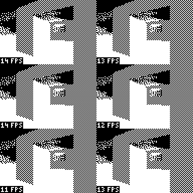
A quick check with my PC program shows that the counter is fairly accurate (close enough for my liking). I can now use these tick counts to scale the movement of the player, so the speed is consistent. Another advantage is that I can set the SE edition calculators to 15MHz, and they can benefit from more fluid framerates (nb: any program I run will still need to run merrily on the 6MHz calcs for me to be happy. I'm not going SE-only!)
That's not to say I can now go and build an exciting level and release a nifty demo. There are still big holes in the engine - simple graphics bugs, like the wall filling code still not supporting top edge slopes with a y difference of over 127: (overflow-related bug)

...to there still not being any proper occlusion (sorting)...

I'd like to get occlusion up and running, so I can throw a nifty level together (for example, showing off non-90° walls). Thing is, it's tricky trying to show off cool stuff and not walk into an area where you can see the world isn't quite as solid as it should be. ![]()
Filling
Friday, 7th July 2006

I chucked some simple filling in to the engine as a test. It scans along the top and bottom edges of the shape, then fills columns. This is rather inefficient (filling scanlines is much faster - the screen is shorter than it is wide, so tracing Ys for the boundaries is faster than scanning Xs, and when filling by scanline you can write 8 pixels - a byte - in a single shot) but it served the purpose of a quick demo. It's rather broken, and doesn't match the lines correctly (so there are slight gaps and overflows). It's only temporary.
I'd like to extend the filling to support different dithered fills - white, 25%, 50%, 75% and black walls would look nice.
There is no sorting as yet, I just arranged the walls in back-to-front order in the level file.
@philipptr: I don't know if you ever completed your triangle filling, but the way I've done it in the past is to split the triangle into two halves (y0→y1 and y1→y2, where y0<y1<y2). I would then trace down the sides of the triangle, calcuating the X bounds for the top and bottom halves (Bresenham), then filling in the horizontal lines using these values. Only uses integer arithmetic, so nice and fast.
Whether this will be turned into a game or not depends on whether I can get it to scale sensibly with decent-sized levels; especially with the addition of scaled sprites. If I can get a nice sized level that you can walk around nicely, then I'll try and add a game - pointless planning a game around an engine that isn't up to par!
Clipping works! (Almost)
Monday, 3rd July 2006
Clipping now works in nearly all cases:

One of the problems was lack of precision. Here's the typical case that worked, running in my mockup:
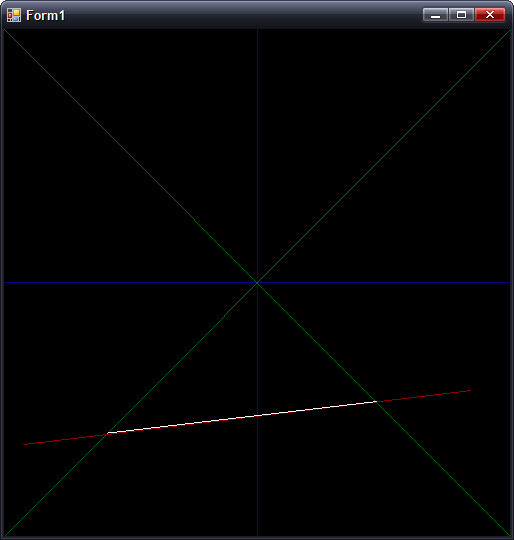
In this case, where |dX| > |dY|, all is good. However, switch that around so that |dY| > |dX|, and you get the following:
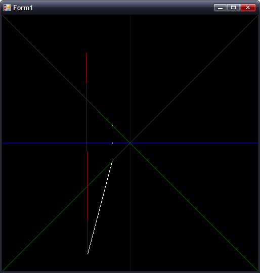
(Fixed point isn't so good for holding values that tend towards infinity). The solution is to have two branches for the clipping arithmetic, switching to the alternative form when |dY| > |dX|.
Preparation:
m = (Y1 - Y0) ÷ (X0 - X1) ; m is negative gradient.
c = Y0 + m × X0 ; Not sure what to call this, but it's used in all the below calculations
Clipping to y = 0:
x = c ÷ m
y = 0
Clipping to y = +x:
y = c ÷ (1 + m)
x = +y ; not used as we can skip having to transform.
Clipping to y = -x:
y = c ÷ (1 - m)
x = -y ; not used as we can skip having to transform.
The reason for clipping to y = 0 is to make sure the line is clipped to the correct side.
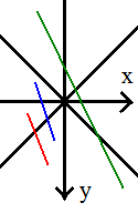
If you look at the red and blue lines, you can see that the far out-of-range points both have x < 0. This indicates that you should clip to y = -x. However, the green line also has the far end at x < 0, but we actually need to clip to y = +x. We can fix this problem by first clipping to y = 0, then checking the sign of x.
To fix the steep gradient problem, I just need to switch to these alternative sums:
First up, the gradient and c are calculated as:
m = (X0 - X1) ÷ (Y1 - Y0) ; Flipped
c = X0 + m × Y0 ; Again, X/Y flipped.
For clipping to y = 0:
x = c ; No need to divide by m!
The only other difference is to make sure that when clipping y = -x:
y = c ÷ (m - 1) ; as opposed to (1 - m)
...and all is hunky-dory.
The only remaining problem is if you are positioned directly inside a wall, which collision detection should fix.
Clipping
Tuesday, 27th June 2006
Clipping (adjusting walls to ensure that they are in the field of view so that they can be drawn correctly is being a right pain).
Firstly, I rewrote some of the really ugly wall-handling code:

Clipping follows the fairly simple maths:
(Where m is the gradient of the wall). The resulting Clip value then corresponds to the new (X,Y) coordinate - if you want to clip to x=-y all that's needed is (1 - m) becomes (1 + m) and Clip must be negated before using it as the new X coordinate.

The result (with added adjustment layer to turn the grey clipped line into red for clarity's sake) seems to work pretty well.

...or not. When implemented with the rest of the code, something goes rather wrong when I look at the wall from the wrong side. Thankfully, that was a simple bug in the division routine, causing it to trash the accumulator when one of the operands was negative (the accumulator itself formed part of one of the operands).

With that fixed, things look a bit more positive, but it's still rather unstable.
Latenite 1.0.6.0
Tuesday, 20th June 2006
There's a new Latenite beta - 1.0.6.0 - available from my site. I hope this is the last Latenite 1 release; I'm moving away from the current IDE towards a revised Latenite 2, the focus more on interactivity with the assembler and the debugger (better 'Intellisense', breakpoints, variable watching and so on). This mainly revolves around a much improved text editor, currently in the works.
Not a very exciting thing to look at, but handling text selection, editing, copying, pasting, and highlighting - and keeping it fast - is being a bit of a pain.
For the most part, it is fast enough, but gets seriously sluggish when scrolling up and down at high resolutions (has to repaint the entire control as none of it is buffered).
That little 3D engine for the calculator I was working for (codenamed Nostromo) is not dead, as you might have thought;

(Old screenshot to refresh your collective memories). I have recently 'ported' the TASM-style code to the new Brass syntax, rewritten all of the wall handling code for increased performance and fixed some of the graphical glitches caused by overflow (lines wrapping incorrectly around the display). I have increased the resolution and accuracy of the maths in use as well, but it's still pretty sluggish with large amounts of data and still lacks occlusion and wall clipping to the view.
One (easy) way of speeding things up would be to split the world up into 'rooms' (or zones, pick whatever terminology you like) where each room is entirely self-contained and cannot be seen from any other room. By opening and closing doors between rooms you can add and remove which rooms are in the list to be drawn, keeping the geometry count low.
Of course, for this to work, I'd need a bit of collision detection to be able to work out which room the camera is in. ![]()
In terms of occlusion, I'm a bit stumped. As far as I can tell, BSP might be the way to go, but have never been able to write a working 'BSP engine'. If anyone had any links they'd recommend on the theory and implementation behind this, I'd be very grateful.
Applications
Wednesday, 7th June 2006
I've been attempting to add native TI-83+/TI-73 application support to Brass. Testing with Flash Debugger has been an entertaining experience, not least thanks to helpful messages like:
I haven't managed to get a signed application running in Flash Debugger or on hardware yet - I suspect the header is wrong - but seeing as the demo application has a different header structure to what the header generator creates, and both have generally conflicting information, I need to find some better resources.
If you want to sign applications from C♯ via Wappsign, this wrapper around the COM object might be useful. You'd use it like this:
// Sign the app (where BinaryFile is the filename of the .hex file to sign)
try {

    AppSigner Signer = new AppSigner(AppSigner.Mode.DetectType);

    // Get the key file
    string KeyFile = Signer.GetKeyFile(BinaryFile);
    if (KeyFile == "") throw new Exception("Couldn't find the key file.");

    // Get the output filename
    string SignedAppFilename = Signer.FormatOutput(BinaryFile);
    if (SignedAppFilename == "") throw new Exception("Couldn't establish output filename.");

    // Sign the bugger
    int Signed = Signer.Sign(BinaryFile, KeyFile, SignedAppFilename);
    if (Signed != 0) throw new Exception(Signer.GetErrorMessage(Signed));

} catch (Exception ex) {
    // Didn't work as it should
    DisplayError(ErrorType.Error, "Could not sign application: " + ex.Message);
}
Variable height sectors
Wednesday, 12th April 2006
I switched from 16/8 division to 24/16 division, and wall heights are now calculated rather than being dragged off a lookup table.

There's also backface culling (the cylinder around the central cube is marked as double-sided, hence no culling there) but there is still no clipping or occlusion.
@philipptr: I'm guessing your technique is to calculate the angle of the point, add an offset to it, then convert back into a new coordinate? I just adapted some 3D point rotation code I had, simplifying (mathematically) it and removing any references to z.
I will probably not use textured walls - not so much for performance issues, but for aesthetic reasons. Scaling a texture down on a wall displayed on a 96x64 monochrome display (without antialiasing) looks pretty ugly. Simple lines look a lot cleaner.
Oh, and hello aCiD2 ![]()
Oldschool 3D
Wednesday, 5th April 2006
All this DOOM work had got me interested again in simple 3D engines, and so thoughts turned to my favourite Z80 platform, the TI-83 Plus.
There are a handful of 3D engines out there for it already; Matt3D is a vector-based wireframe engine put to good use in a roller-coaster builder/simulation game and a racing game (that even supports two-player over the link port). However, it's 8-bit and so worlds created with it tend to be very small or distorted thanks to low-resolution (I tried writing a Quake game with it years ago).
The best "wall" engines (displaying a 3D world rather than a 3D object) have been the raycasters. Gemini impresses me the most; it's a Wolfenstein-level engine with objects, sliding "half-block" doors and moving wall blocks, all neatly texture-mapped.
I'm going to try, therefore, to get a vector-based "wall" engine (there must be a proper term for it) up and running. Keeping the map to 2D simplifies the maths a lot; hopefully with a few tricks things should be fast enough! Also, I'll use 16-bit arithmetic throughout to enhance the quality and scale of the maps.

Like DOOM, I'm isolating the vertices from the wall definitions. This way, I can cut down on the number of rotations/transformations required. The maths required to rotate a point around the origin is fairly simple;
Yr = Xo × cos(a) - Yo × sin(a)
For the moment, I'll use a simple lookup-table for wall heights. Ultimately, I'd like to have variable height walls, but these will do for the moment:

The translated X is just 48+(Xr/Yr), as the screen is 96 pixels wide.
Throwing in a few extra lines for walls...

As you might be able to see, there is no clipping if any part of a wall falls outside the viewing range. Also, the walls are not occluding eachother, something you'd really want.
CHIP-8/SCHIP
Monday, 27th February 2006
It's not as if I didn't already have an excess of projects, but anyway...
The binaries are here. I've tested them fairly extensively on my TI-83 Plus, but be warned that (as it's beta) they might cause odd crashes. Back up any important files!
TI-83 Plus Mouse
Tuesday, 21st February 2006
I had another go with my AT protocol routines to see if I could persuade a PS/2 mouse to do anything.
It would appear that I could...
There are two cables for the mouse as there were for the keyboard - one goes to the TI, the other goes to the power supply. The mouse is put into the lowest resolution mode (the cursor is moved 1 pixel per mm).
There's a demo for anyone with a TI-83 Plus and an adapter. It also contains a keyboard demo - and there's a video of that demo here (1MB WMV).
Fortunately, I didn't have to butcher that mouse (it's a rather good miniature USB/PS2 one), but it is connected to the TI with Blu-Tak to keep the wires on the contacts, and isn't very mobile as I only gave the power lead about 15cms clearance. I think it's high time I grabbed myself some proper connectors and a soldering iron from Maplin... ![]()
As for the mouse routines - they need a lot of tidying up and making much more reliable, especially in the recovery when a mouse is disconnected then reconnected (my keyboard routines are 'hot pluggable', after all). Extending them to support the Microsoft Intellimouse system, giving the mouse an extra axis (scroll wheel) and two extra buttons would be rather cool as well.
Ultimately, these routines are rather useless until they become widely adopted. Ideally, they could/would be added to a shell, and form part of the standard routines. For example, the shell could provide a "get key" function, which would also transparently return keyboard keys as if they were keys on the keypad, or return four "left" keys if the mouse was moved 4 mm left -- that sort of thing.
Chances of this happening are, sadly, nil. ![]()
Microhertz
Monday, 13th February 2006
They say that pictures are what make a journal interesting... but I don't really want to show the pretty pictures I have, as they'd spoil the surprise. Of what, you might ask? Well, I've been developing a TI-83/83+ scene demo, entitled "Microhertz" (for no particular reason). You can download it (and some screenshots, if you really must!) here.
Things have been very busy - a new Latenite beta, riddled with all new exciting "features" (*cough*), has been released... I'm slowly fixing them as and when I can ![]()
It's a bit rubbish for debugging - you can start, pause, and stop a debugging session, but that's about it. Hopefully it won't be too long until I get around to actually sorting out all the debugging gubbins, but I'd rather get the main IDE and the primitive debugging more stable first.
One other TI project I'm working on is updating QuadPlayer. I have a 1.1 version which can play songs from the archive as well as RAM, has a loop function and other little fixes and tweaks. To complement it, I've written a simpler script for creating your own songs, a better Windows-based player for testing (which simulates QuadPlayer's internal sound generation system and has accurate timing) and (best of all) am working on a program that takes PSG VGM files (BBC Micro, Sega Master System &c) and converts them to QuadPlayer songs. So far, any songs that do "exciting" things - vibrato, for example - end up sounding horrible in high octaves (I'm having to limit 10-bit to 8-bit periods), but I have some very decent sounding QuadPlayer files based on Sega VGMs. Some songs use lots of short, fast notes - which sounds great on dedicated hardware, but when you have a delay as QuadPlayer stops outputting a square wave to fetch the next note, sounds crap.
Debugging...
Thursday, 12th January 2006
CoBB has added an non-interactive mode to his emulator. I'd never thought about using stdin/stdout to pass information between executables; but it works well (once I've ironed out the bugs at my end, that is!) All I need to do is pass it instructions via stdin then read back the results (such as a screen dump) through stdout. This can then be, hopefully, used to pass instructions back to Latenite ("Highlight line 43 on file source.asm", for example, to show where the PC is).
TI Z80 Development Gets Cool
Tuesday, 10th January 2006
This excites me greatly - integrating a debugging emulator into Latenite is very, very awesome. CoBB's emulator is incredibly good as a standalone, being able to step through your code instruction-by-instruction with breakpoints and a watch window or two is just amazing! ![]()
I spent most of the last few days working on Brass - adding for loops to assemble blocks of code multiple times and a few file operations for people not happy with the behaviour of .incbin. I also remembered to release an XML help file for Latenite.
The Marble Madness engine project has been plodding along in the background - I've written a fast masked, clipped, 16x16 sprite routine and have started tackling the big problem of mapping the ball's 3D coordinates to the screen (easy) and then to a heightmap (hard) for Physics.

Have a marble rolling off a ledge then bouncing off the right screen boundary. ![]()
Scrolling Marbles, Fire Track ROM
Friday, 6th January 2006
Fire Track
Prompted by a PM from evolutional, I rebuilt a working-ish version of Fire Track.
Keys should be fairly self-explanatory; hold down button 1 and 2 as the ROM loads to get access to a cheat screen. Of course, you'll need an emulator; Emukon is a highly advanced, but suprisingly fast emulator (fast in that it lets me run GG ROMs at full speed on an old Pentium PC).
I will be uploading all the source and tools in a zip at some point so you can experiment with some of the other features if need be.
Marble Madness
I started work on a 4-way smooth scrolling tilemapper last night for use with the Marble Madness project (for the main view) and have come up with a fairly simple, but sufficiently fast mapper.

The GIF is a little wasted as the level is only 128 pixels wide, and on a 96 pixel wide display this doesn't give much room for showing off the smooth x-scrolling. Having never written a mapper like this (only basic, slow horizontal scrolling and vertical scrolling, never together) it was quite an experience, but not as hard as I'd thought.
I have cobbled together a basic editor that allows me to edit the map, and that takes a folderfull of GIF files and exports a binary sprite resource file. Hooray RAD with C#!
It looks like I'm going to need a lot of sprites... ![]()
As for this crashing and burning - Fire Track failed because of my absolute lack of music skill; also, the game was too hard to be any fun.
Marble Madness is just a set of ideas; I'm not comitted to it (hence no "official" announcement to any TI people, kv83!)
Lost my Marbles
Thursday, 5th January 2006
First up, happy Christmas (or "Seasons Greetings" to the politically-correct amongst you - I've never heard this supposed "Happy Holidays" said in this part of the world, and in any case the word Holiday seems to indicate religious goings-on in any case, so we'll be having none of that PC rubbish ![]() ).
).
Back to the Z80
Having spent a week away in Normandy, marooned from the world of the Intarwebs and PC, I have come up with a potential new Z80 project. I had my Game Gear with me (naturally) and one of my games was the most excellent Game Gear port of Marble Madness:
The game is simple if you do not know it; you must guide a marble through an obstacle course to the finish in under a certain time. Various tricky level design elements and enemies make this a hard task. The world is presented in an scrolling isometric 3D view.
The Game Gear is not an especially powerful platform; the Z80 runs at ~3MHz. The TI-83 Plus runs at 6MHz (an underclocked 8MHz Z80). Of course, the Game Gear has the bonus of hardware-accelerated smooth-scrolling (which is how we get super-fast games like Sonic on it) but Marble Madness has fairly simple basic scrolling; vertical smooth scrolling on a TI is cheap, and horizontal smooth scrolling only needs to go one pixel at a time for Marble Madness - we can't do much about that apart from bitshifts, but a pixel/frame isn't asking for too much.
In a bizarrely well-organised move I ended up taking along a pen and paper, and ended up making a bunch of notes on how to construct a Marble Madness engine.
Graphics
For this game, it all boils down to the way the graphics are presented to make or break the gameplay. They need to accurately convey the illusion of a 3D world, whilst at the same time being handled internally as very primitive - we can't do CPU/memory expensive things like treat the world as a true 3D model and have a 3D isometric engine.
Also, the limitations of the display and LCD driver of the TI-83 Plus need to be taken into consideration. The TI-83 Plus is equipped with a 96x64 pixel monochrome LCD. It is accessed through the use of a driver chip on ports $10 and $11. As it is monochromatic, a single byte represents 8 entire pixels. The physical display is 12 bytes wide and (there are 64 rows); in reality it is 16 bytes wide, but normally the 4 bytes are off the edge of the display. It can be set into a special 6-bit mode where each byte only covers 6 pixels; the 6 pixel columns are squashed up to give us a 16-column display, but this is only really useful if you are, say, using it for a 6x8 font (the TI-OS uses this mode for the text-mode screens).
For this reason, horizontal scrolling is cheap; you can just change the byte offset as you copy to the buffer to scroll up and down. However, horizontal scrolling requires (expensive) bit-shifting. Not only that, but the display operations have to be timed using inefficient loops (push af \ inc hl \ dec hl \ pop af is common - there is no accurate timing hardware) else it decides to do useful things such as jump into 6-bit mode. The whole TI graphics system is very sluggish.
The low resolution needs consideration; the Game Gear Game relies on clean, large, colourful graphics. I will have to drop the resolution down so that you can see a decent region around your marble; and can't afford to use effects such as dithering which make the display unclear (the display is quite blurry).
Here is a sample course (thanks to Maxim for producing the map):
To fit it on the TI, I have decided to halve the resolution. If I kept the squares as tightly packed as in the Game Gear version, this would result in 4x4-ish tiles - mucky, cluttered and ugly. To remedy, I shall have to expand the tiles to double their visible width/height; so a single tile in my version would cover 4 tiles on the Game Gear version. The levels would have to be adjusted (in the image above, the tile blocks at the top are arranged in 3x3 grids; I shall probably go for 2x2 grids of my larger tiles, or just go straight to 1x1...
The way I intend to handle the levels would be to split them up into their individual parts;
- Background - this would be a simple 2D tilemap, made up of 8x8 tiles with a fast smooth-scrolling engine. This is rendered, then the marble/enemies are copied on top of it.
- Heightmap - this is a sort of 2D map of the 3D world, where each point has two values - a type (flat, steep slope, empty space, goal...) and a relative height. This would be used by the physics engine to handle the movement of the marble around the level.
- Depth map - this is a sort of copy of the 2D tilemap, but only contains special masked copies of the tiles on the tilemap, together with a depth (z-index). This way, when the ball is drawn the tiles that it is convering can be checked. If the corresponding tile in the depth map is closer to the user, it is redrawn, concealing part of the ball. For example, see the railings in the picture of the level above, or any of the large holes. As most of this layer will be empty, it could be RLE compressed fairly succesfully.
Other things, such as animated sprites or dynamic parts of the level, would be handled separately. For example, level 2 has this tilty thing:

It tilts up and down. For this, a special large sprite could be rendered, and the 3D heightmap in memory adjusted as required.
I'd be interested to hear any thoughts/ideas/pointers on my methods...
Business with the Z80
Monday, 12th December 2005
I have been pretty busy with Brass and Latenite over the last few days - Latenite has had a few little adjustments/improvements/fixes, but also has a few new holes in it which means that it is unsuitable for release. I'm adding the ability to hook help files to projects rather than each project being loaded with every help file - this has the extra bonus that Brass will be able to compile help files straight from the source, which will then be reloaded on each build by Latenite.
I did something unheard of over the weekend as well - I read the SDK manual for the TI-83 Plus. Mainly because I was trying to work out how some of the function calls worked, but also the stuff they talk about with regards to applications (as opposed to programs - applications fill multiple 16KB pages of ROM on the calculator, programs are variable sizes and are copied to RAM location $9D93 for execution) was pretty interesting - and it sounds pretty nightmarish! I'll download some of the application development tools, see if I can puzzle them out and then try and recreate their behaviour in Brass. It's yet another output format - Brass can, with the .binarymode directive, switch between a number of binary output formats, including TI calculator formats (TI-73, TI-82, TI-83, TI-83+, TI-85, TI-86), raw binary and a number of hex text files (Intel, Intel word address, MOS technology and Motorola).
I'd never really understood how the LCD display driver worked on the TI-83 Plus, and the SDK documentation was pretty useful - even though I still can't quite work out why the X axis goes from top-to-bottom and the Y axis goes from left-to-right. It turns out direct access to the LCD can produce some very fast results... (and the world's worst greyscale):

Download binaries for TI-83/TI-83 Plus [Ion/MirageOS]
Yes, yes, I have a little 'something' about 3D tunnels.
Localisation
Thursday, 17th November 2005
Typing
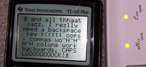
One reason you'd want to connect a keyboard to your TI - or indeed any device - would be to type on it. After all, it offers a nice comfortable layout to type quickly on...
One easy way to deal with the keyboard as a typing device would be to write a function that converts the scancode into an ASCII code (or a special code in the 128→255 range for keys without sensible ASCII equivalents, such as the Windows or cursor keys). But here's the problem - not all keyboards have the same characters printed on the keys. A UK layout will be QWERTY, a French layout will be AZERTY and a German layout will be QWERTZ. A US keyboard will have @ over the 2, whereas my keyboard has " over the 2.
The way I get decided to get around this was a fairly inelegant (but simple) one - assume the calculator has a keyboard localisation file on it. A function call I have provided called keyi_load_table will attempt to find and load the keyboard layout definition file you can create (returning an error code if it can't find any). Any software that uses these routines can therefore instantly tailor themselves to match the keyboard layout of the individual user. The files themselves aren't very big - it contains two mappings for the entire keyboard (normal and shifted), a table of which keys Caps Lock affects (26 bytes - A→Z on an English keyboard) and a final table for alternate codes for when Num Lock is pressed.
With this all put together, a single call to keyi_translate will convert a scancode in the accumulator to the ASCII/special code, automatically adjusting for Shift/Caps Lock/Num Lock. You can even call the function keyi_check_printable to see if the code is in the printable character range, or keyi_get_status_icon to get a character code for a suitable cursor - no special status returns , shift returns ↑, caps lock returns A and caps lock+shift returns a.
Getting it to work
Wednesday, 16th November 2005
Reliability
I'm sure you wouldn't want to use a keyboard that was inaccurate. Unfortunately, (as you might have seen me moaning in the past) the keyboard generates the clock signal. This basically means you need to be constantly checking the clock line to see if it goes low - that or use a hardware interrupt the jumps in and receives the scancode packet when the keyboard decides you want to stop sending something.
Well, I don't have the luxury of an extra keyboard chip or a hardware interrupt, so I needed to don my thinking cap. I had thought that one possible way around this would be to send a "disable" command to the keyboard after receiving bytes, running my handler code, then sending an "enable" command - these commands clear the keyboard's buffer, unfortunately, which is not good.
I downloaded another document on the AT protocol to see if they mentioned anything useful, and lo and behold:
The host may inhibit communication at any time by pulling the Clock line low for at least 100 microseconds.
I think I can spare 100µs - I added the line ld a,1 \ out (bport),a to the end of my buffer-filling code from earlier (it fills a scancode key buffer) - and the code doesn't drop a single scancode. Result!
Providing useful functionality
All these keyboard routines do at the moment is to display the data coming in on the screen - not exactly a great use of them. What is really needed is a simple two-way handler - it calls two different user-defined routines based on what a key is doing, whether it is being pushed down or released.
For this, I should translate the scancodes into a new format - there are less than 256 keys, so there's no reason why I can't fit every single key into a byte.
As well as user-defined keyboard events, I'll have to add my own to handle toggling the status of the keyboard - the num/caps/scroll lock as well as the shift/alt/ctrl.
It's really quite simple to do.
	; Now we need to run through all the keyboard events!

	ld ix,_buffer	; Start at the beginning of the buffer.

_handle_next_scancode:

	; Let's assume it's a normal key:

	ld hl,_scancode_lut
	ld bc,_scancode_lut_end-_scancode_lut

_key_down_handler:
	ld de,_null_handler


	ld a,(ix+0)
	or a
	jr z,_handled_all_keys

	cp at_scs_enhance	; Is it an enhanced key?
	jr nz,_not_enhanced

		inc ix	; We know it's enhanced, so move along.
		ld a,(ix+0)
		or a
		jr z,_handled_all_keys
		ld hl,_scancode_e_lut
		ld bc,_scancode_e_lut_end-_scancode_e_lut
_not_enhanced:

	; Now HL points to our LUT, BC is the correct length
	; and IX points to the next byte.

	cp at_scs_keyup ; Is it a key UP event?
	jr nz,_not_keyup

		inc ix
		ld a,(ix+0)
		or a
		jr z,_handled_all_keys
_key_up_handler:
		ld de,_null_handler

_not_keyup:

	; Move to next chunk before we do anything
	inc ix
	; At this point, A=scancode, HL->translation table, DE->handler, BC=table size, IX->next scancode.

	; We now need to run the translation.

	cpir	; Simple as that!

	jr nz,_handle_next_scancode	; Not found

	; So HL->scancode+1
	; Here is where the magic happens:

	push de
	ld de,0-_scancode_lut
	add hl,de
	ld a,l
	pop de

	; Now, A = 'real' scancode.

	; We need to 'call' DE.
	; We can spoof this easily:

	ld hl,_handle_next_scancode
	push hl	; _h_n_s is on TOP of the stack.
	push de ; our event handler is on top of the stack;
	ret	; POP back off stack and jump to it.
		; When the handler RETs it'll pop off _h_n_s and carry on scanning!


_handled_all_keys:

_null_handler:
	ret
I created a couple of very basic event handlers - the key down event displays ↓ followed by the adjusted key code, the key up event displays ↑ followed by the adjusted key code.
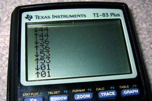
What would be ideal would be to provide internal event handlers that could be called on keyup/keydown which would then jump over to the user's custom handler. These event handlers could look for special keys and adjust the keyboard LEDs and set internal flags that could be used to detect the status of certain keys. I'd need:
- Num Lock
- Caps Lock
- Scroll Lock
- Shift
- Ctrl
- Alt
Unfortunately, I think that there is a problem with my byte-sending code. Setting the keyboard LEDs starts to do strange things - I now have two options;
- After switching status, ignore the LEDs. The status flag is set correctly internally, but you can't see it on the keyboard (which is a bit pants).
- Update the status flags every single time we run through the loop to check for any new bytes (which makes the keyboard lag like crazy - there's up to half a second of buffering going on!)
Mixing-and-matching the two - rewriting the branch before we bring the clock high again (for maximum speed) confuses the keyboard - the status LEDs never change and it decides to disable itself in a strop until I send $FF (the reset command) again. I think it's time to revisit the at_send_byte routine again to see what it's doing wrong!
Well, comparing it to my new notes - it's actually completely wrong at the end, when it comes to sending the parity/stop/ACK bits! A quick rewrite to how I think it should go isn't too hopeful - the keyboard LEDs flash like mad. Tweaking the timing by throwing in a few calls to _wait_bit_low and _wait_bit_high to synchronise my data to the clock stop this completely - and now the code is as it was before, at 100% accuracy - but about twice as fast.
Replacing my branch code still doesn't work all the time - sometimes the LEDs change, sometimes they do not. Not believing it would work, I threw in a check for the ACK bytes returned - if they were $FE, the 'repeat last command' byte, I'd send again.
My routines were clearly not as broken as I thought - the keyboard LEDs now change status perfectly, and as much as I hammer the Num Lock, Caps Lock and Scroll Lock keys, I cannot lock up the program or get the keyboard LEDs to display the wrong value. Not to mention that keying in other keys is back to the lightning fast response they used to be...
TI Keyboard
Tuesday, 15th November 2005
Once again, I waste my time doing something remarkably useless - it's trying to connect a keyboard to my TI graphing calculator!
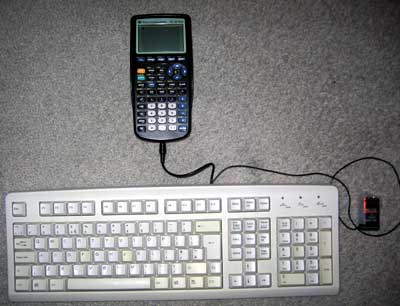
Idea
Alas, this is not an original idea - I had seen some work done on this in the past, and tried fiddling with the code myself, not really understanding much of it. I decided to have a go - from scratch, and on my own.
Constructing the hardware
I decided to butcher an old, suitably discoloured keyboard (in a nice way, though, so if all went wrong I could reassemble it). I don't have a soldering iron, nor any sort of decent cabling or plugs so I planned to just cut and strip the wires inside the keyboard and attach (by twisting together and large amounts of Sellotape) a power cable and 2.5mm stereo minijack plug (the TI has a 2.5mm stereo minijack socket on it as a data port).
I'm not sure they put enough screws into this thing... (by contrast, my main keyboard has a whopping 2 screws in it - this keyboard's designer was clearly paid by the screw!)

Finally (and with a slightly sore wrist), I get to the bit I need - the keyboard controller board. The circuit board has the four leads soldered straight into it - I'd been hoping for the more typical sight of a block that the cable plugs into, but unfortunately it looks like I'll be cutting wires and hoping not to snap them off by accident. The four wires have been labelled VCDO - I'll cross my fingers and assume these stand for VCC (+5V), Clock, Data and 0V.
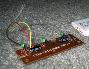
Out it comes, the wires are stripped and reattached. I then tested all the leads using my multimeter and created some stunning ASCII art to remind me what went where:
HARDWARE SCHEMATIC:

PS/2 SOCKET:                               TI CONNECTOR:

  6.-++-.5      4: VCC   >-[+5V]                _
  /o || o\      5: Clock >---< 1: Red    Tip   /_\.
 |   ++   |     1: Data  >---< 2: White  Ring  }_{
4|o      o|3    3: Gnd   >-+-< 3: Copper Base  | |
  \      /               __|__                 |_|
   \o__o/                 ---  0V             /   \.
   2    1                  '                  \___/===> To TI
 ^ Note that this is the SOCKET view
and not the plug view for a PS/2 port.
With that done, I taped down the connections and screwed the whole thing back together. Tapping a 9V PP3 battery to the power leads makes the keyboard boot up; doesn't look like it's broken quite yet!
Writing the code
What with the hardware now hopefully complete, it's a simple case of writing the code to support the keyboard. *cough cough*
Basically, I need to write an implementation of the AT protocol. The protocol is fairly simple, but unfortunately the keyboard generates the clock signal for us (the TI doesn't have accurate timing at all - it's an RC circuit, and so the clock rate drops as the batteries go flat). Let's hope the TI can keep up!
I guess the easiest code to write would be code that sets the output high (as it's an open collector circuit, high is the default level - either side can pull this low and hold it there) then poll the clock and wait for it to drop then go back up again. The clock line maps to bit 0 of the link port, and the data line to bit 1 of the link port. The TI's data IO port can be controlled using these two lower two bits of the hardware port equated as 'bport' (port 0) in ti83plus.inc
Here's what I tried;
init_all:
    ; Set link port high
    ld a,%00000011
    out (bport),a


wait_bit_low:
    in a,(bport)        ; Read in the status of the bport.
    and %00000001       ; Mask out bit 0 (clock)
    jr nz,wait_bit_low  ; Is it non-zero (high?) If so, loop back.

wait_bit_high:
    in a,(bport)        ; Read in the status of the bport.
    and %00000001       ; Mask out bit 0 (clock)
    jr z,wait_bit_high  ; Is it zero (loop?) If so, loop back.

    ret                 ; Break out of the program
Strange, whatever I do - init the keyboard, tap keys, nothing happens. The program goes into an endless loop. Using the 9V to manually set the line low then high again, I realise something - I keep forgetting that the port works backwards, and that writing %00000011 sets the status to %00000000 - and when a line is held low by either device, it can't be brought up again very easily. Replacing the offending line with xor a to clear it to zero worked a treat - pressing any key on the keyboard exits the program.
Each "packet" on the AT protocol (it's a bit grand to call it that) is made up of 11 bits - 1 start bit, 8 data bits and 2 parity/stop bits. A djnz loop to get the 8 bits and a handful of rotate instructions to populate the result byte gives me this:
.module AT_Protocol

at_timeout = 255

at_get_byte:
    ; Clear Link port
    xor a
    out (bport),a

    ; Get the start bit:

    call _wait_bit_low
    call _wait_bit_high


    ; Now we need to get the 8 bits for the byte

    ; Reset the output byte
    ld c,0

    ld b,8

_get_byte_loop:

    call _wait_bit_low

    ; Now we get the bit itself
    in a,(bport)
    rrca
    rrca
    rr c

    call _wait_bit_high

    djnz _get_byte_loop

    ; Get the parity/stop bits

    call _wait_bit_low
    call _wait_bit_high
    call _wait_bit_low
    call _wait_bit_high

    ; Clear flags, load code into accumulator and exit
    xor a
    ld a,c
    ret

_get_byte_fail:
    ; Set nz to indicate failure, return.
    or 1
    ret


_wait_bit_low:
    push bc
    ld b,at_timeout
_wait_bit_low_loop:
    in a,(bport)
    and 1
    jr z,_waited_bit_low
    djnz _wait_bit_low_loop
    pop bc
    pop bc
    jr _get_byte_fail
_waited_bit_low:
    pop bc
    ret

_wait_bit_high:
    push bc
    ld b,at_timeout
_wait_bit_high_loop:
    in a,(bport)
    and 1
    jr nz,_waited_bit_high
    djnz _wait_bit_high_loop
    pop bc
    pop bc
    jr _get_byte_fail
_waited_bit_high:
    pop bc
    ret
Not too tricky at all! Amazingly, this code ran first time too. (Amazingly for me, that is). The test program just reveices a byte from the keyboard and displays it on the screen.
One minor problem is that sometimes the code received differs by a bit to what it should (you can see this by holding down a key and noting how sometimes the code is different - I've written a short program that just displays the code on-screen when it's received). Consulting my AT protocol notes, I find that "After the clock line goes low a 5-microsecond pause is used so that the data line has time to latch." Maybe my pause isn't long enough?
Sadly, that did quite the opposite - the results are even more unpredictable. I guess it would be more better to try speeding up my code, rather than slowing it down..?
After increasing the speed a little (without unrolling all the loops, that is) the routines are (by and large) slightly more accurate. Still not perfect, but they'll do for the time being. If I press a key the release it just before it repeats, the accuracy is 100% perfect - I suspect that the problem is that in the time the rest of my program has drawn the last keycode, the keyboard has pottered away and tried to output another byte and I'm jumping in half way through. I guess I'll have to write some clever buffering code to handle that!
Interrupts
I thought that an ideal way to handle the timing/speed problem was to create a piece of code that could be loaded as a sort of driver. The calculator would be set up into interrupt mode 2 and would call the driver 100-or-so times a second. The code could then try to see if a byte was coming in, and if so it would add it to a buffer. A routine isolated from the rest of the code could then read a byte from the buffer and shift all the other items down to replace it - a sort of FIFO stack.
The Z80 has three interrupt modes; 0, 1 and 2. Interrupt mode 0 is pretty useless to us; interrupt mode 1 is the normal mode of operation. In this mode, the CPU pushes the program counter to the stack then jumps to memory location $38 every time an interrupt occurs. The interrupt handler then swaps the main CPU registers away with their shadow register pairs, does something, then swaps the CPU registers back again. Finally, you pop the old program counter off the stack and jump back to where you were. You could think of it as having a second thread running, only a lot less hi-tech and more restrictive.
Interrupt mode 2 is a stranger beast. The main difference is that it doesn't just jump to $38 - it creates a 16-bit address using the register I as the most significant byte and a byte off the data bus as the least significant byte - effectively, we have a 16-bit number made up of i*256+?. The CPU then loads the value in the memory location pointed to by this 16-bit value, then calls this address.
What does this mean for us? Well, it means that rather relying on the interrupt at $38 we can load our own interrupt into memory!
We need to do three things:
- Create a 257-byte lookup table aligned to a 256-byte boundary for the CPU to read from after it has build up the 16-bit address.
- Set the I register to the most significant byte of the start address of our lookup table.
- Copy our interrupt handler to the location our table points to, switch the interrupt mode to two and enable interrupts.
The way I've done this is:
- Filled memory locations $8700 to $8800 (inclusive) with the byte $86.
- Loaded $87 into the I register.
- Copied my interrupt handler to $8686
My interrupt handler at $8686 is a simple jp instruction to jump back to my program for the sake of practicality.
Unfortunately, this approach doesn't work (and I tried a lot of different ways to get it to!) One reason for failure is that in im 2, the main interrupt handler at $38 isn't getting executed. The TIOS relies pretty heavily on this interrupt to work; most functions cause a pretty nasty crash or do other strange things. Fine, I say to myself, and replace my reti call at the end of my interrupt handler with a jp $38 to manually call the TIOS interrupt. The behaviour gets even stranger - calling ionFastCopy (a function, non-TIOS related, to copy the display buffer to the LCD) causes strange rippling effects to appear on the LCD, followed by a full-out crash when I finally quit the program.
On top of all this, the few times I can get a display of the key buffer I can see that it's not updating very frequently... The interrupt is not checking the port frequently. All this for nothing!
As far as I can see it, the only way for an interrupt-based technique to work would be for the TI to have a hardware interrupt - using the keyboard's clock connected to the CPU, so that whenever the clock goes low the TI could spring into action and receive the byte. Seeing as the only access to the CPU I have without invalidating my warranty is via the data port, I'm a bit stuck.
Back to square one
I guess the only way is to agressively poll the port... First up, I rewrote the code so that instead of displaying a decimal version of the code, I'd display a hexadecimal version - significantly easier to read, faster to convert. I then painstakingly noted down every key's scancode from this into a useful include file.
One problem with the original TI keyboard project was that it had problems with input; it would occasionally forget about shift being pressed, or accidentally repeat keys. I think I now know why...
On an AT protocol keyboard, scancodes are sent every time a key is pressed and again when the key is released. To differentiate between the two different actions, when a key is released the scancode is preceded by the special code $F0.
I reckon that the problem was that the function to get a byte would have been called, followed almost immediately with the code to translate/display it. What I intend to do instead is to get bytes in a loop and add them to a buffer until either the routine times out (no more bytes being sent) or the buffer is full (shouldn't happen!)
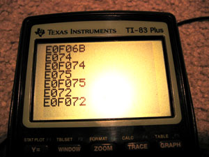
As you can see, this system works. The above codes are special ones generated by pressing some of the extended keys (the cursor keys) - they send the code $E0 followed by the key itself. Some of the codes are downright silly - PrintScreen sends the command string E0F07CE0F012 when released - Pause sends E11477E1F014F077!
Infuriatingly... this is STILL not perfect! I'm still losing some bytes. What to do - if only there was a way to control the keyboard, to stop it from scanning... wait a minute...
Controlling the Keyboard
Sending a byte is not too different from receiving a byte - you hold the clock and data lines low, then just the data low, then write out the bits as the keyboard requests them on clock. The easiest code to transmit is $FF - keyboard reset. According to my notes, the keyboard should respond with the power-on self-test byte as well as resetting. Lo and behold, the keyboard lights flash and I get $AA back - the self test has passed. I also get $E8 back, and my notes don't mention $E8 anywhere, but I'll ignore that for a minute and bask in the glory of it otherwise working perfectly.
The next code I try is $EE. This is the echo code - in theory, the keyboard should send back $EE. Sadly, it doesn't. Damn. It just resets and sends back $AA, though it sometimes sends back $B8 as well.
On close inspection, it seems pretty obvious what I've done wrong - I'm completely neglecting to send the parity and stop bits. Oops. After adding them, the keyboard responds $EE to my $EE - which is quite correct! The parity is hard coded, so I'm glad it works.
Trying another code, $F2, gets the keyboard to spit back an unfriendly $FE - which translates as "resend, you idiot". $EE is %11101110, which contains 6 set bits. $F2 is %11110010 which contains 5 set bits - the parity needs to be reversed. Hopefully calculating the parity shouldn't consume too many clock cycles - after I extract the bit to send, I need to add it to another counter. I can then use the lowest bit of this counter as my parity bit.
Thankfully, I have sufficient time to calculate the parity - the keyboard now responds FAAB83. $FA is the ACK code, AB83 are the ID bytes. Scarily, my notes say that the ID bytes are $83 then $AB - I'm going to hope that this is an error in the notes - I doubt my routines are going to be able to mix up whole bytes!
Now for the main reason you'd want to send codes to the keyboard - to flash the LEDs, of course! The code is $ED - the keyboard should respond with an ACK ($FA), to which I send the status byte (the lower 3 bits control the LEDs). The code is pretty simple (albeit without any checking on the ACK):
    ld a,$ED
    call at_send_byte   ; Command
    call at_get_byte    ; ACK
    ld a,%00000101      ; Caps Lock and Scroll Lock on
    call at_send_byte   ; Command
    call at_get_byte    ; ACK
Ace. I'll add the equates for the various commands to my include file. No doubt I can get some more done with this project tomorrow...
On the merits of Excel and running out of space
Monday, 12th September 2005

Latest video. [2.29MB AVI]
You chaps probably don't know what a major headache it is trying to get clear, non-wobbly video... ![]()
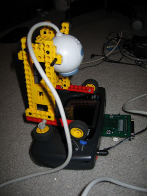
I gave up in the end and went for the "propped-up against a wall with camera on stack of books" approach. The reason I cannot, therefore, appear to play the game very well is because I cannot see the screen. All I can see is a faint, inverted glow and have to guess where I am. Not fun.
Here are the major updates since last time:
- Removed Blackadder theme

- Altered colour contrast on title screen, added wipe to clear it in imitation of original, restructured code for better fades, changed timing, added sound. Title screen is now complete.
- Rewrote entire code for checking bullet collisions with buildings on the ground from scratch. It now works perfectly.
- Levels now "start" correctly, so the ship moves in from the bottom, the start platform moves towards you very fast until they are in the correct positions, at which point gameplay commences (much smoother than just dumping you at the start position with a full level already there).
- All levels now mapped correctly, in order, with correct palettes for backgrounds AND sprites. Levels that end a zone with a platform rather than with the face are flagged as such and the correct end is substituted in now.
- Each level can be pointed at a 'replacements' table, which lists "replace tile X with tile Y". Tiles are swapped around properly so that levels appear more varied.
- Explosions are now fully implemented (2 kinds, background and foreground - with very slightly different animations) and working.
- Path-based enemy attacks are now in full working order, using paths generated with a combination of my graphical calculator and Excel.
- A couple of other new enemy attacks have been added.
- The game now sports a BBC Micro font which can be used for proper text display.
- The "epilogue" to the game is fully coded (type-writer effect for final message copied from original game, including sound effects and fades).
- Each level now begins with a summary screen (sprite limits meant that displaying all your lives at the start of the level was impossible, so is now done on an interval screen). The screen displays the zone name and a number of lives, the number of lives being surrounded by orbiting space-ships (the number of those being the number of lives left).
- The game now fully works on hardware (should now work on old hardware - not checked, as I do not have an old BIOS-less Game Gear) and in all emulators (I was not initialising the display correctly).
- Destroyed terrain tiles are not updated live to the name table in the fairly intesive loop - they are saved to a list of destroyed tiles, which are then read off directly and updated when needed in the intensive graphics bit.
I've probably forgotten a lot of stuff. Bear with me.
There have been a number of "WTF" moments reading back some of the source. Take, for example, this gem:

Some explanation is needed here - this is from the code that handles the special case when you have shot a 2x2 square building and it lies out of bounds of the name table. The name table is my grid (32x28) of tiles indices that each point to an 8x8 tile in the VRAM. As the view point moves up this map, new tiles indices are written to it, or old ones are adjusted when something is blown up. The worst case scenario here is if the 2x2 tile lies just above the top of the name table - which is what the above code has to fudge. Look at this:
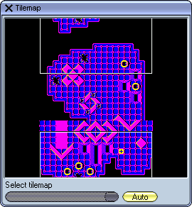
(I love debugging emulators!)
This shows all of my 32x28 tilemap. That funny white rectange is my view rectangle (it's currently half-off the display, and it loops around). If you look at the top and bottom edges of the tilemap, you'll see a ring has been shot out. Naturally, the bottom will have been hit first. What happens in this case is the address of the tiles that have been erased is decremented by a whole row of map points (there are 2 bytes to a spot on the name table, so I go backwards by 64). In this case, I find that the address is above the start of the tilemap so I add on 64*28 (which is the entire size of the table) and add it back to get back into the bounds of the table itself. As you can see, it was a successful operation in this case, but only because I was writing back HL this time and NOT the accumulator! No wonder my sprites were becoming destroyed as I was writing in completely the wrong part of the VRAM...
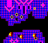
This is the screenshot from the emulator of the screen display for the above tilemap (the sprite layer is not displayed in the tilemap, for obvious reasons).
I'm still not getting very far with my quest for music. ![]()
The only bit of the game that has music is the title screen, and that's not so much music as a weird noise (here is an MP3 of my Game Gear's rendition, this is the original from the BBC Micro). Even though I have specified that the noise channel (the one that produces the high beeping noises) to use the highest frequency, it's still lower than the Beeb. All the other notes are correct, though.
Latenite has got yet another update - project support. (It looks more and more like VS.NET every day!) Rather than create messy proejct files and stuff which makes distrubution tougher, I thought I'd go the easier route of just allowing people to stick directives in the file with the ;#latenite:main directive. You can now ;#latenite:name="name_of_project" and ;#latenite:project="file_name"[,"project_folder"].
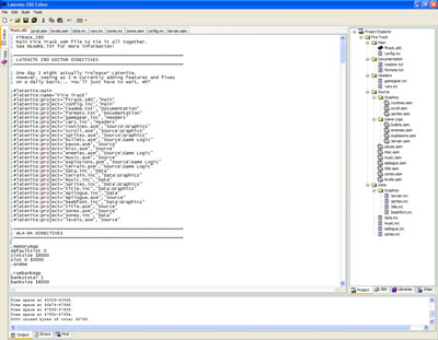
Click for larger image
Skybound Visualstyles (which I'm using to fix the weird .NET XP interface bugs) looks lovely but hugely slows down the app - only really noticeable with so many hundreds of nested controls like me and when moving large windows on top of it forcing repaints, so now the XP styling option is saved away (so you can revert to boring standard grey if you like). Latenite now saves window/splitter positions when you close - a first for an app by me! ![]()
In fact, Latenite is also my first app that needs a splash screen, it takes so long to get going... ![]() It's only about 2 seconds, though, for it to track down all the tools, load all the documentation, add all the compiler scripts and present itself, so it's not too bad.
It's only about 2 seconds, though, for it to track down all the tools, load all the documentation, add all the compiler scripts and present itself, so it's not too bad.
One overlooked piece of software is Microsoft Excel. People seem to develop a hatred of it, especially in people who end up trying to use it as a database application (it appears that this is what 9 out of 10 smallish (and some not so small!) companies do).
I have been using Excel to create those smooth curving paths for some of the enemies to follow. First, I prototype them on my graphical calculator (lots of trial and error involved!):
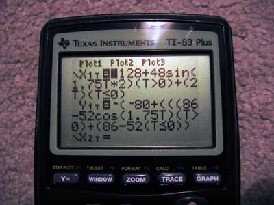
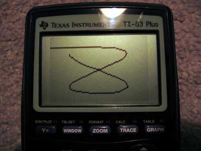
..before transferring into an Excel spreadsheet.
The Excel spreadsheet is set up so that column A is the steps (usually 0 to 256) in ascending order. Column B is the X coordinate, column C is the Y coordinate.
Columns E and F serve a special purpose - they contain the differences between each element in columns B and C (so E3=B3-B2, E4=B4-B2 and so on). Columns G and H "fix" the values - if it's negative, make it positive and set the fourth bit (just add 8). This is for the internal representation of the paths. Column I contains the data I can just copy and paste into the source files - it starts with the initial (x,y) coordinate, and then has a list of bytes. Each byte signifies a change in (x) and change in (y), with the lower four bits for (x) and the upper four bits for (y).If the nibble is moving the object left or up (rather than right or down), then the most significant bit of that nibble is set. For example:
%0001 - move right/down 1 pixel
%0011 - move right/down 3 pixels
%1001 - move left/up 1 pixel
%1100 - move left/up 4 pixels
...and therefore...
%11000001 = move right one, up four.
Poor Excel has suffered a little bit of neglect from me - I used to use it to generate my trig tables. WLA-DX, the assembler I learn to love more and more every day, supports creation of a number of different tables - including trig tables - with a single directive. Just specify .dbsin (or .dbcos) followed by the start angle, how many bytes of trig table you want, the step between each angle, the magnitude of the sine wave and the DC offset and away it goes.
People still using TASM, STOP! Use WLA-DX. It's ace (and free, not shareware!).
You can never have enough pictures in a journal (hey, you should see this page load on our 700 bits/sec phone line at home!)
Here's the full list of sprites:
![]()
The last ship being after the explosions is a mistake, but it's too much hassle to change. I'm really pleased the way they've come out - I'm no pixel artist. ![]()
I'll finish off with a few assorted screenies.
...I would have done. I should have done. However, when taking those screenshots I saw a glitch in the graphics. As an exercise for the reader, can YOU spot where the bug is?
(and it's not in one of those external functions I wrote - this is why copy-paste coding is bad, 'kay?)
Oh, (possibly?) final last thought popping into my head: one thing I really miss from the BBC Micro era is the comfortable keyboard layout. I mean, look at this small photo of a Master 128 keyboard:
Click for bigger
You might think that that blocky monstrosity would knacker your fingers, but that's not the reason. It's the fact that rather than squash one hand's fingers onto a small cursor pad (or the even sillier WASD), you balance movement between your two hands - Z and X for left and right, : and / for up and down. (On a modern UK layout, that'd be ZX and '/). The space bar is now conveniently accessible by both thumbs, and you can reach around most of the rest of the keyboard with your other fingers.
The Game Gear is an ergonomic handheld (unlike the uncomfortable Game Boy), so I'm reckoning that I can balance the controls between hands - ← and → on the d-pad can control left and right, and the 1 and 2 buttons can control up and down. I will offer multiple layouts, though, as otherwise that might confuse some people. ![]()
Anyway, I hope you find this journal interesting. It seems a bit all over the place - video, pictures, rambling, odd bugs, nostalgia... The only thing that's an issue is my rapidly shrinking GDNet+ account web space!
Finished the levels! Wahey!
Wednesday, 7th September 2005
...and here is level 6. This, however, worries me:
Hopefully I can cram in all the rest of the code, tables, graphics and music into 5K. Failing that, I might have to start compressing my levels...
I don't believe I've introduced you to my enemies yet? Here's the complete sprite table - don't worry, the letters P, A, U, S, E and D do not feature as enemy craft!
![]()
I spent some time adding a new command systen to QuadPlayer, so you can now set a song to loop back X times (or infinitely) to a particular spot. It'll only loop from the end, sadly. Nested repeats will be too evil to try and implement. I'd like to experiment more with white noise - maybe a command to set up certain channels as being white noise rather than tones? Not sure how I'd generate the white noise, as the register R (which is the source of my random number generators) isn't going to be very random if accessed in a short loop!
Sample song, from a Kirby game (I added the fade at the end manually, that's not produced by the calculator!) Not bad, seeing as it has been generated by a calculator with no proper sound hardware. ![]()
QuadPlayer - four channel sound from a TI-83 Plus
Monday, 18th April 2005
No longer are we limited to two channels of sound, but here we have access to four!

If you have a TI-83 Plus calculator, there's a preliminary release here - and if you don't, some zipped up MP3 recordings here.
Z80 ASM and PICAXE
Wednesday, 13th April 2005
I've been doing all sorts of odds and ends recently. I've acquired a Sega Game Gear, and so have started taking a look at programming on that - it has a Z80 CPU in there, so the languge isn't an issue, more so the hardware. Ah well, I can display a screen of text and cycle the colours around so far - nothing impressive, but the setup works.
I've also been playing with PICAXE microcontrollers again. Here is a pair of routines that can be used to get/send bytes using the TI hardware link protocol, for example. I am yet to do anything useful with them, however.
Windows programming has never been my favourite side of things, but I have also started work on a Z80 ASM "IDE" called Latenite:
It's mostly there, but now needs features galore to be added. So far it can be used to compile and source code, which is the main thing.
Subscribe to an RSS feed that only contains items with the TI-83+ tag.
